Preparation is the key to success in any interview. In this post, we’ll explore crucial Blueprint Interpretation and Detailing interview questions and equip you with strategies to craft impactful answers. Whether you’re a beginner or a pro, these tips will elevate your preparation.
Questions Asked in Blueprint Interpretation and Detailing Interview
Q 1. Explain the difference between an architectural and structural blueprint.
Architectural and structural blueprints, while both integral to construction, serve distinct purposes. Architectural blueprints focus on the aesthetic and spatial design of a building. They show the arrangement of rooms, walls, doors, windows, finishes, and other design elements. Think of them as the building’s ‘look and feel’ plan. Structural blueprints, on the other hand, delve into the engineering aspects, detailing the load-bearing elements, foundation design, framing systems, and other components critical to the building’s stability and safety. They are the building’s ‘bones’ and ensure its structural integrity.
For example, an architectural blueprint will show the placement of a fireplace, while a structural blueprint will illustrate the supporting beams and chimney structure necessary to safely accommodate it. One defines the space, the other ensures it stands.
Q 2. What are the standard symbols used in blueprints?
Blueprint symbols are standardized to ensure clarity and efficiency across the construction industry. While slight variations might exist depending on the country or company, many are universally recognized. Common symbols include:
- Lines: Different line weights and styles (solid, dashed, dotted) represent various elements like walls, dimensions, centerlines, etc.
- Shapes: Circles, squares, and rectangles denote fixtures, equipment, or other components. For example, a circle might represent a light fixture, while a square could indicate a plumbing fixture.
- Symbols: Standardized icons represent doors, windows, electrical outlets, plumbing fixtures, and HVAC systems. These icons are often accompanied by annotations to clarify sizes and specifications.
- Leader Lines and Dimensions: Leader lines connect symbols to dimensions or annotations clarifying size, material, or other attributes.
A comprehensive symbol key is usually included on the blueprint itself to avoid ambiguity. Think of these symbols as a visual shorthand, allowing quick comprehension of complex information.
Q 3. How do you interpret scale on a blueprint?
Scale on a blueprint indicates the ratio between the drawing’s dimensions and the actual building’s dimensions. It’s typically expressed as a fraction (e.g., 1:50, 1/4″ = 1′) or a ratio (e.g., 1:100). This means that one unit on the blueprint represents a certain number of units in reality.
To interpret the scale, you simply use the given ratio. If the scale is 1:50, every 1 centimeter on the drawing represents 50 centimeters in the real building. Similarly, if the scale is 1/4″ = 1′, each 1/4 inch on the blueprint represents one foot in the actual construction. Understanding the scale is crucial for accurate measurements and calculations during construction.
For instance, if a wall measures 3 inches on a blueprint with a scale of 1/4″ = 1′, the actual wall length will be 3 inches * (4 feet/inch) = 12 feet.
Q 4. Describe your experience with different CAD software.
Throughout my career, I’ve gained extensive experience with various CAD (Computer-Aided Design) software packages. My proficiency includes AutoCAD, Revit, and SketchUp. AutoCAD is my go-to for precise 2D drafting and detailing, especially for producing precise shop drawings and construction documents. Revit, with its Building Information Modeling (BIM) capabilities, has been invaluable for complex projects requiring 3D modeling, coordination, and quantity takeoffs. SketchUp’s user-friendly interface is advantageous for initial conceptualization and quick design iterations. I am comfortable adapting to new software as needed and always eager to improve my skillset within this rapidly evolving field.
For example, on a recent project, I utilized Revit to create a detailed 3D model of a multi-story building, allowing for effective coordination of mechanical, electrical, and plumbing systems. AutoCAD was then crucial for creating detailed shop drawings for the steel fabricators and other contractors.
Q 5. How do you identify conflicts or errors on a blueprint?
Identifying conflicts and errors on blueprints requires meticulous attention to detail and a systematic approach. I typically follow these steps:
- Thorough Review: I begin by meticulously reviewing each drawing, paying close attention to dimensions, notations, and symbol consistency.
- Cross-referencing: I carefully cross-reference drawings to ensure consistency between architectural, structural, mechanical, and other disciplines. Discrepancies in wall thicknesses, door locations, or utility lines are common areas for conflicts.
- Dimension Verification: I check dimensions for accuracy and consistency, looking for conflicting measurements or omissions.
- Code Compliance Check: I verify that the design complies with relevant building codes and regulations, identifying potential violations early in the design process.
- Clash Detection Software: For larger projects, I utilize clash detection software to identify conflicts between different building systems (e.g., MEP clashes with structural elements).
By systematically following these steps, I can effectively pinpoint errors and propose solutions that improve the project’s overall efficiency and safety. For example, I once discovered a significant clash between the HVAC ductwork and a structural beam, which I resolved by proposing a minor adjustment to the duct routing. This prevented costly rework during construction.
Q 6. Explain your process for creating detailed drawings from conceptual sketches.
Transforming conceptual sketches into detailed drawings involves a structured process. It starts with understanding the design intent behind the sketch: its style, scale, and overall functionality. Then, using the sketches as a guide, I refine and translate them into a more structured format, usually starting with a preliminary layout in CAD.
Next, I add layers of detail, gradually building upon the initial layout. I accurately dimension all components, ensuring consistency and adhering to project specifications. Material specifications, construction methods, and other vital information are clearly annotated. I utilize established drafting standards to maintain a clear and organized representation of the design.
Throughout this process, continuous review and revision are vital, ensuring accuracy and consistency in all aspects. The final product reflects the initial conceptual sketch yet fulfills all necessary construction requirements. Think of it as sculpting – the initial sketch is the clay, and the detailed drawings are the refined sculpture.
Q 7. How familiar are you with building codes and regulations?
I have a thorough understanding of building codes and regulations, including the International Building Code (IBC) and local variations. My familiarity extends to various aspects of building design, construction, and safety, such as fire safety requirements, accessibility guidelines (ADA compliance), and structural load calculations. I consistently incorporate code requirements throughout the design and detailing processes, ensuring compliance and avoiding potential issues.
Regularly reviewing updated codes and participating in industry workshops are essential to staying current with changes and best practices. Prioritizing code compliance isn’t just about avoiding penalties; it’s about ensuring the safety and well-being of building occupants and workers.
Q 8. How do you manage revisions and updates to blueprints?
Managing revisions and updates to blueprints is crucial for maintaining accuracy and avoiding costly errors during construction. We employ a rigorous version control system, typically using a centralized digital repository like Autodesk BIM 360 or similar platforms. Each revision is clearly identified with a revision number and a description of the changes made. This allows us to track changes, revert to previous versions if necessary, and ensure everyone is working with the most up-to-date version.
For example, if a plumbing fixture needs to be relocated, a new revision will be created, clearly indicating the change on the affected floor plan and any related sections or details. This new revision is then distributed to the relevant team members, with clear communication about the changes and their impact.
We also maintain a comprehensive revision log, documenting the date, author, and a detailed description of every change. This is vital for auditing purposes and helps resolve discrepancies should they arise.
Q 9. Describe your experience with BIM (Building Information Modeling).
My experience with Building Information Modeling (BIM) is extensive. I’m proficient in using software like Revit and ArchiCAD to create, manage, and coordinate building models. BIM is not just about creating 3D models; it’s about leveraging the data within those models for better project management and collaboration. I’ve used BIM to create clash detection reports to identify potential conflicts between different building systems (like MEP and structural), leading to more efficient design solutions and preventing costly rework on site.
For instance, on a recent project, BIM allowed us to identify a clash between a ductwork run and a structural beam before construction began. This early detection saved significant time and resources by avoiding the need for costly on-site modifications. Furthermore, the ability to extract quantities directly from the BIM model simplified the estimation and procurement processes, leading to more accurate budgeting and scheduling.
Q 10. How do you collaborate with other team members on blueprint projects?
Collaboration is paramount in blueprint projects. We utilize a variety of tools and strategies to ensure seamless teamwork. Regular team meetings, both in-person and virtual, are crucial for discussing design decisions, reviewing progress, and resolving issues. We rely on cloud-based platforms to share and manage files, enabling real-time collaboration and feedback. Software like BIM 360 allows for simultaneous access to the same project files, fostering a streamlined workflow.
We also leverage communication tools such as Slack or Microsoft Teams for quick queries and updates. Clear communication protocols and defined roles ensure everyone understands their responsibilities and contributes effectively. This collaborative environment fosters a shared understanding of the project, minimizes conflicts, and ultimately results in a high-quality product.
Q 11. Explain your experience with different blueprint types (e.g., floor plans, elevations, sections).
My experience encompasses a wide range of blueprint types, including floor plans, elevations, sections, details, and schedules. Floor plans provide a bird’s-eye view of a building’s layout, showing the arrangement of rooms and spaces. Elevations depict the exterior appearance of a building from different angles, showcasing design features like windows and roofing. Sections reveal the internal structure and composition of a building along a specified plane, illustrating relationships between different building elements.
Construction details, often drawn at a larger scale, provide intricate information about specific building components, such as connections or material specifications. Schedules are tabular representations of information, such as door schedules or window schedules, providing a concise summary of building components and their attributes. Proficiency in interpreting and creating all of these drawing types is essential for comprehensive understanding and efficient execution of construction projects.
Q 12. How do you handle ambiguous or incomplete information on a blueprint?
Handling ambiguous or incomplete information requires a proactive approach. First, I thoroughly review the entire set of blueprints, looking for clues that might clarify the ambiguous area. If the information is unclear, I’ll consult the project specifications and any other relevant documents. If uncertainties remain, I’ll proactively communicate with the architect, engineer, or project manager to seek clarification. It’s crucial to document these queries and the resolutions obtained.
For example, if a dimension is missing on a floor plan, I might cross-reference it with adjacent plans or sections to estimate the missing value, but I’d always document this estimation and inform the project team to confirm. This prevents assumptions from leading to significant errors during construction.
Q 13. What is your experience with creating construction details?
Creating construction details is a critical aspect of my work. I’m adept at producing clear, accurate, and detailed drawings that effectively communicate the construction methods and material specifications for specific building components. These details are essential for contractors to understand how to build the project according to the design intent. I have experience creating details for a variety of components including connections (e.g., beam-column connections, wall framing), finishes (e.g., tile installations, flooring), and other critical elements.
The process typically involves careful analysis of the architectural and structural drawings, along with consultations with relevant engineers and contractors. I use appropriate conventions, scales, and annotations to ensure clarity and ease of understanding. I often create 3D models to visualize the details prior to drawing them in 2D, ensuring that the final construction details are accurate and efficient.
Q 14. How do you ensure accuracy and precision in your blueprint work?
Ensuring accuracy and precision is paramount. We use a multi-layered approach involving rigorous quality control checks at each stage of the process. This includes utilizing accurate software and tools, employing appropriate scales and drawing standards, and implementing detailed cross-checking methodologies. We frequently employ independent checks and verifications, where one team member reviews the work of another to catch potential errors before they reach the construction site.
For example, all dimensions are meticulously verified using mathematical calculations and cross-references. Detailed annotations are used to specify materials, sizes, and tolerances. Furthermore, we use digital tools to automatically check for inconsistencies and clashes, significantly enhancing accuracy and minimizing potential errors. This meticulous attention to detail is crucial for mitigating risks and ensuring the successful execution of the project.
Q 15. Describe your proficiency in using AutoCAD, Revit, or other relevant software.
My proficiency in AutoCAD and Revit is extensive, spanning over [Number] years of professional experience. I’m highly proficient in 2D drafting and 3D modeling, using these tools daily to create, modify, and manage construction documents. I’m not just familiar with the basic functionalities; I’m adept at leveraging advanced features like parametric modeling in Revit for efficient design iteration and Dynamo scripting for automation. For example, on a recent project involving a complex multi-story building, I used Revit’s family editor to create custom components, significantly reducing modeling time and ensuring consistency across the project. In AutoCAD, I’m skilled in using various drawing tools, layer management techniques, and external references (Xrefs) to maintain clean and organized drawings, even on large, collaborative projects. Beyond AutoCAD and Revit, I also have experience with [List other relevant software, e.g., Navisworks, Civil 3D] which allows me to contribute effectively throughout the entire building lifecycle.
Career Expert Tips:
- Ace those interviews! Prepare effectively by reviewing the Top 50 Most Common Interview Questions on ResumeGemini.
- Navigate your job search with confidence! Explore a wide range of Career Tips on ResumeGemini. Learn about common challenges and recommendations to overcome them.
- Craft the perfect resume! Master the Art of Resume Writing with ResumeGemini’s guide. Showcase your unique qualifications and achievements effectively.
- Don’t miss out on holiday savings! Build your dream resume with ResumeGemini’s ATS optimized templates.
Q 16. How do you interpret dimensional tolerances on a blueprint?
Interpreting dimensional tolerances on a blueprint is crucial for accurate construction. Tolerances define the permissible variation from the nominal dimensions. They’re usually indicated using symbols and numerical values. For instance, Ø10 ± 0.2 means a diameter of 10 units with a tolerance of plus or minus 0.2 units; the acceptable range is 9.8 to 10.2 units. Understanding these tolerances is paramount; otherwise, components might not fit together correctly. Different types of tolerances exist, including unilateral (allowing variation in one direction only), bilateral (allowing variation in both directions), and geometric tolerances (specifying limits on form, orientation, location, and run-out). I always meticulously check the tolerance specifications on blueprints before detailing to avoid potential issues during fabrication and construction. On one occasion, a seemingly small tolerance oversight in a critical structural component could have led to significant problems. Recognizing and addressing it early saved time and considerable costs.
Q 17. How do you create accurate and clear annotations on drawings?
Creating clear and accurate annotations is key to effective communication. My approach involves using consistent lettering styles, clear labels, and precise referencing. I follow industry standards, such as those outlined in ANSI or ISO standards, for consistent labeling of dimensions, materials, and other details. For instance, I use leader lines to clearly connect dimensions to specific features. I meticulously ensure that all annotations are legible and unambiguous, avoiding ambiguity that can lead to errors in construction. I leverage the annotation tools within AutoCAD and Revit to create professional and standardized annotations. Furthermore, I always maintain a consistent layer structure to organize annotations and maintain a clean drawing environment. Using revision clouds to highlight changes and adding notes to explain significant design choices enhances clarity and traceability. I consider the audience for the drawings – whether they are contractors, fabricators, or engineers – and tailor my annotations to ensure they are easily understood.
Q 18. Explain your approach to troubleshooting discrepancies between blueprints and on-site conditions.
Troubleshooting discrepancies between blueprints and on-site conditions requires a systematic approach. My first step involves thorough verification of the blueprint’s revision status to ensure I’m working with the most up-to-date version. Then, I meticulously compare the drawings with the actual site conditions, documenting all deviations using photos, sketches, and detailed notes. I prioritize discrepancies based on their potential impact on the project. For example, a small deviation in wall thickness might be less critical than an offset in a structural element. I then collaborate with the project team – architects, engineers, and contractors – to determine the cause of the discrepancies and propose appropriate solutions. This could involve issuing revised drawings, adjusting construction methods, or even revisiting design decisions. Often, it’s a matter of careful investigation; sometimes, it’s something as simple as a misinterpretation of the drawings, while other times it may point towards a need for design changes or clarifications. I’ve had situations where seemingly insignificant discrepancies on-site ultimately exposed errors in the original design, highlighting the importance of this reconciliation process.
Q 19. Describe your experience working with different types of materials and their representation on blueprints.
My experience encompasses a wide range of materials commonly used in construction, including concrete, steel, wood, masonry, and various finishes. I’m familiar with their representation on blueprints; for example, concrete is often depicted using hatched patterns, while steel might be represented using solid lines with specified dimensions and material grades indicated in a material schedule. I understand how material properties influence design decisions. Understanding material representation helps in evaluating the constructability of the design and identifying potential material conflicts. For instance, understanding the properties of different types of wood allows me to verify if a specific type is appropriate for a given load-bearing application. Experience helps recognize and understand the symbols and notations used to represent different materials, including their tolerances and finishes. I also have experience in using material take-off tools in Revit to accurately quantify the quantities of materials needed for construction.
Q 20. How do you prioritize tasks when working on multiple blueprint projects simultaneously?
When juggling multiple blueprint projects, prioritization is key. I use a combination of techniques. First, I analyze project deadlines and critical milestones, identifying those requiring immediate attention. I then assess the complexity and interdependencies of the tasks across projects. Urgent, high-impact tasks take precedence. I break down large projects into smaller, manageable tasks, enabling me to make progress on several projects concurrently. I utilize project management software to track progress, manage deadlines, and ensure effective communication. Regularly reviewing my task list, adjusting priorities based on emerging needs, and maintaining open communication with stakeholders are essential aspects of my approach. This helps avoid bottlenecks and ensures timely completion of all projects. It’s like a conductor orchestrating a symphony – each instrument (project) plays its part, and the conductor ensures they harmonize, resulting in a beautiful outcome.
Q 21. What is your understanding of different projection methods used in blueprints?
Blueprints primarily employ orthographic projection, a method of representing three-dimensional objects on a two-dimensional plane using multiple views (plan, elevation, section). Each view shows a different aspect of the object from a specific direction. Understanding these views is essential for interpreting the entire design. I am also familiar with isometric and axonometric projections which provide three-dimensional views, useful for visualizing the overall design. Furthermore, I understand how sectional views help to show interior details not visible in plan or elevation. I can interpret and create all these different projection types using AutoCAD and Revit. Proper interpretation prevents misunderstandings during construction. For example, not understanding how a section cut is taken can lead to misinterpretations of component connections and spatial arrangements.
Q 22. Explain how you ensure the legibility and clarity of your detailed drawings.
Ensuring legibility and clarity in detailed drawings is paramount for effective communication and accurate construction. My approach involves a multi-faceted strategy focusing on consistent use of standard symbols, clear annotation, and organized presentation.
- Consistent Use of Standards: I meticulously adhere to relevant drafting standards (e.g., ISO, ANSI) to ensure symbols, line weights, and text styles are universally understood. This avoids ambiguity and promotes a professional look.
- Clear Annotation: All dimensions, materials, and specifications are clearly labeled with precise measurements and notes. I use callouts and leader lines to pinpoint details accurately, avoiding any guesswork. For example, instead of just showing a dimension, I’ll clearly state “Diameter 10mm” or specify material like “Steel, Grade A36”.
- Organized Presentation: Drawings are organized logically, with clear sheet numbering, a title block containing all relevant project information, and a well-structured arrangement of views (plans, sections, elevations, details). I use layering effectively within CAD software to manage complex information and simplify the overall appearance. Think of it like a well-organized filing cabinet; everything has its place and is easily retrievable.
- Scale and Units: The scale is always clearly indicated, and I consistently maintain the units of measurement throughout the document (metric or imperial). This prevents errors arising from misinterpretation of scale or units.
By following these practices, I create drawings that are not only easy to read but also minimize the potential for errors during construction.
Q 23. Describe your process for checking and verifying the accuracy of completed blueprints.
Checking and verifying the accuracy of completed blueprints is a critical step that demands meticulous attention to detail. My process involves several stages:
- Self-check: I conduct a thorough self-check of my work before moving to the next stage, focusing on completeness, consistency, and adherence to standards. I use checklists to ensure I haven’t missed any crucial details.
- Peer Review: A second pair of eyes significantly improves accuracy. I encourage peer review, where a colleague independently checks my work for errors in calculations, dimensions, and specifications. This provides an external validation.
- Software-based checks: I utilize CAD software’s built-in features for detecting clashes, geometric inconsistencies, and missing data. These features act as an automated first line of defense against potential mistakes. For instance, I utilize clash detection tools to identify conflicts between different design elements, ensuring everything fits together correctly.
- Dimension Check: I perform a comprehensive check of all dimensions and tolerances to make sure they are accurate and meet the design requirements. This includes verifying that dimensions are consistent across different views of the drawing.
- Reference Check: I cross-reference the drawings with the design specifications and other related documents to ensure everything is consistent and accurately reflects the design intent. I meticulously compare the drawings to the initial design concept or model to identify discrepancies.
This multi-layered approach significantly reduces the probability of errors, ensuring the blueprints are reliable and suitable for construction.
Q 24. How do you stay updated on changes and advancements in blueprint technology and standards?
Staying current with advancements in blueprint technology and standards is vital for maintaining proficiency in this field. My strategies include:
- Professional Organizations: I actively participate in professional organizations like the American Institute of Architects (AIA) or similar bodies, attending conferences, workshops, and webinars. These provide updates on the latest technologies and best practices.
- Industry Publications: I regularly read industry publications, journals, and online resources to stay informed about new software, standards, and techniques. These resources often provide case studies and practical applications of new technologies.
- Continuing Education: I pursue continuing education courses focused on relevant software (AutoCAD, Revit, etc.) and the latest drafting standards. Many online platforms offer certified courses that cater to this need.
- Networking: I maintain a professional network by engaging with fellow professionals through online forums, attending industry events, and engaging in peer-to-peer learning. Sharing knowledge and experiences is invaluable for staying updated.
Continuous learning ensures that my skills and knowledge remain relevant and I can deliver high-quality, efficient work using the best available technology and following current industry best practices.
Q 25. How do you handle feedback and revisions on your blueprint work?
Handling feedback and revisions is a crucial aspect of the blueprint creation process. I approach it systematically:
- Understanding Feedback: I carefully review all feedback, clarifying any ambiguities or unclear points with the client or stakeholders. Effective communication is essential here.
- Prioritization: Revisions are prioritized based on their impact on the overall design and schedule. Critical changes are addressed first.
- Version Control: I utilize version control systems within my CAD software (or external platforms) to track changes and ensure that all stakeholders have access to the latest version. This allows for easy rollback to previous versions if needed.
- Documentation: All revisions are documented, including the date, description of the changes, and the person responsible for the revision. This creates a transparent audit trail.
- Testing and Verification: After incorporating the revisions, I perform thorough testing and verification to ensure that all changes have been implemented correctly and do not introduce new errors.
This structured approach ensures revisions are implemented effectively, transparently, and efficiently, leading to a final product that meets client expectations and project standards.
Q 26. Describe a situation where you had to solve a complex problem related to blueprint interpretation.
During a project involving a complex multi-story building with intricate HVAC systems, I encountered a conflict between the architectural and MEP (Mechanical, Electrical, and Plumbing) drawings. The architectural plans showed a large duct running through a space already allocated for structural support columns in the MEP drawings. This was a significant clash that could potentially compromise structural integrity and HVAC functionality.
To solve this, I:
- Detailed Analysis: I thoroughly analyzed both sets of drawings to pinpoint the precise location and extent of the conflict.
- Collaboration: I collaborated closely with the architectural and MEP engineers to discuss potential solutions. We explored options like rerouting the duct, modifying the column placement, or redesigning the relevant section of the building.
- Feasibility Study: We conducted a feasibility study evaluating the costs, time implications, and structural implications of each solution.
- Compromise Solution: We ultimately agreed on a compromise solution that involved slightly adjusting the duct routing and minor modifications to the structural support system. This solution minimized disruption while ensuring both structural integrity and HVAC system performance.
- Documentation: All revisions and the decision-making process were meticulously documented to provide transparency and maintain a record of the resolution.
This experience highlighted the importance of collaborative problem-solving, thorough analysis, and clear documentation when dealing with complex conflicts in blueprint interpretation.
Q 27. How do you ensure the security and integrity of blueprint documents?
Ensuring the security and integrity of blueprint documents requires a multi-layered approach:
- Access Control: I strictly control access to blueprint files, using password protection, access permissions, and secure storage solutions. Only authorized personnel have access to sensitive project documents.
- Version Control: Utilizing version control systems within CAD software or employing dedicated version control platforms ensures that only the latest approved versions are used and historical versions are securely archived.
- Data Backup: I regularly back up blueprint files to multiple secure locations, including cloud storage and offline backups. This protects against data loss due to hardware failure or cyberattacks.
- Data Encryption: Where necessary, I employ data encryption to protect sensitive data during storage and transmission. This is particularly important when transferring files electronically.
- Regular Audits: Periodic audits of access logs and security measures are conducted to identify and address any vulnerabilities.
These measures protect the intellectual property and sensitive information embedded within blueprints, ensuring their integrity and confidentiality throughout the project lifecycle.
Q 28. What are your strengths and weaknesses in Blueprint Interpretation and Detailing?
Strengths: My key strengths lie in my meticulous attention to detail, my proficiency in various CAD software packages, my ability to quickly interpret complex drawings, and my strong problem-solving skills. I also possess excellent communication skills, enabling effective collaboration with engineers and other stakeholders.
Weaknesses: While I am proficient in most standard drafting conventions, I am always striving to enhance my knowledge of more specialized and niche drafting standards and technologies. Additionally, while I value accuracy above all else, striving for absolute perfection can sometimes lead to slightly slower turnaround times. I am actively addressing this by improving my workflow efficiency and project management techniques.
Key Topics to Learn for Blueprint Interpretation and Detailing Interview
- Blueprint Reading Fundamentals: Understanding drawing scales, symbols, notations, and their practical application in identifying various building components and their relationships.
- Dimensioning and Tolerances: Interpreting dimensions, tolerances, and specifications to ensure accurate measurements and construction. Practical application includes calculating material quantities and identifying potential conflicts.
- Sections and Elevations: Interpreting sectional views and elevations to visualize the three-dimensional structure and understand the spatial relationships between different elements. This includes identifying hidden details and potential construction challenges.
- Plan Reading and Spatial Reasoning: Accurately interpreting floor plans, site plans, and other architectural drawings. Practical application involves coordinating different building systems and identifying potential design flaws.
- Details and Specifications: Thoroughly understanding construction details and specifications to ensure accurate material selection and construction methods. This includes analyzing specific construction requirements and potential design changes.
- Building Codes and Regulations: Familiarity with relevant building codes and regulations and how they impact blueprint interpretation and detailing. Practical application includes identifying potential code violations and recommending solutions.
- Problem-solving and Critical Thinking: Applying analytical skills to identify inconsistencies, ambiguities, and potential errors in blueprints. Practical application includes proposing effective solutions and design alternatives.
- Software Proficiency (if applicable): Demonstrating familiarity with relevant CAD software (AutoCAD, Revit, etc.) and its application in blueprint interpretation and detailing.
Next Steps
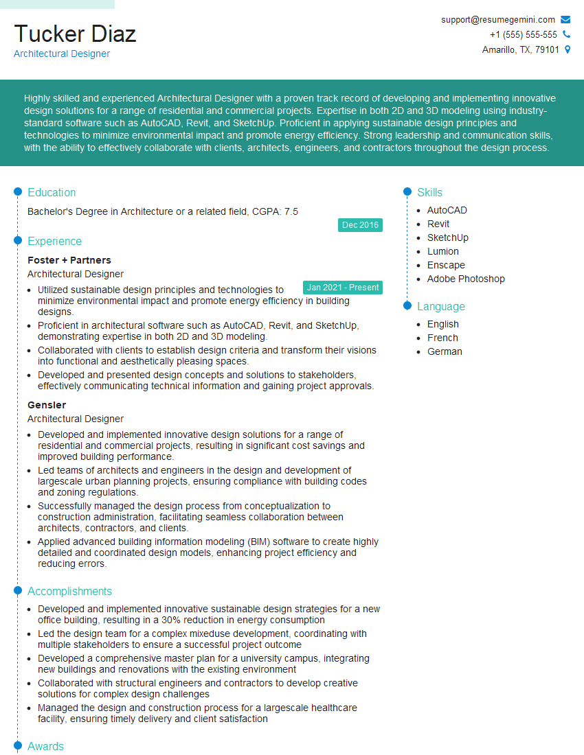
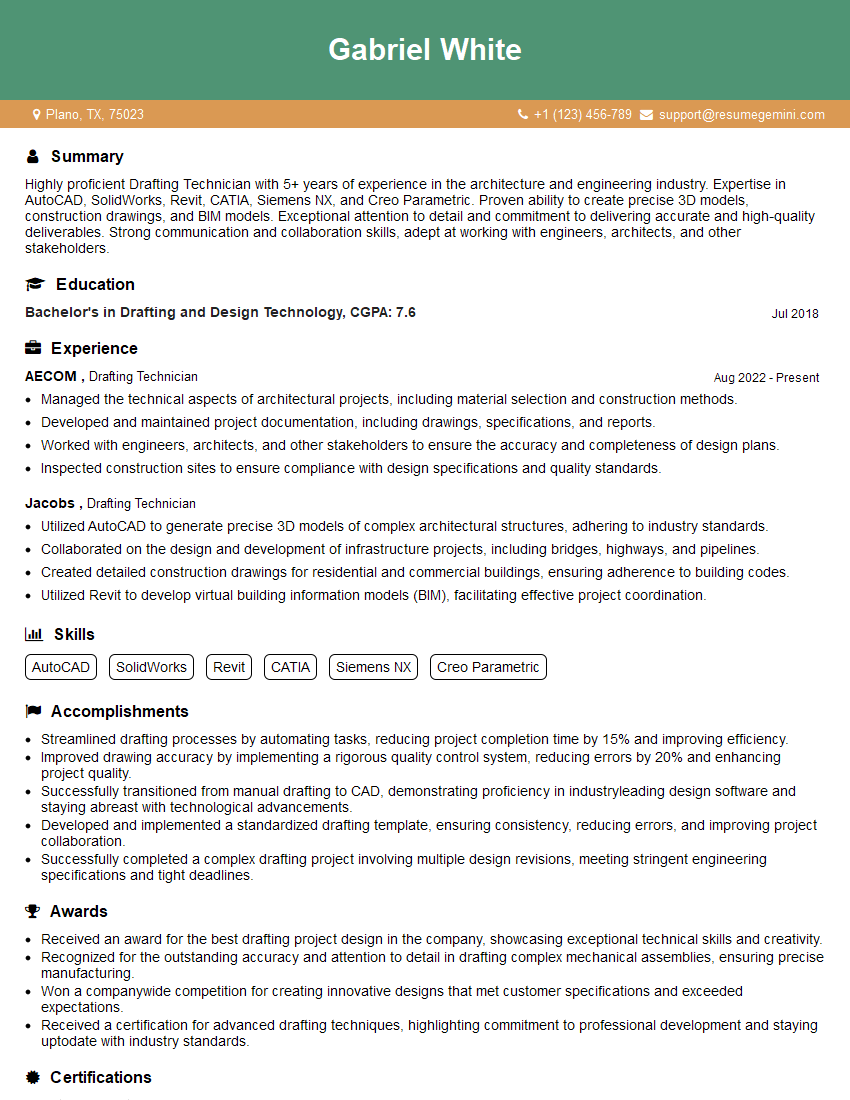
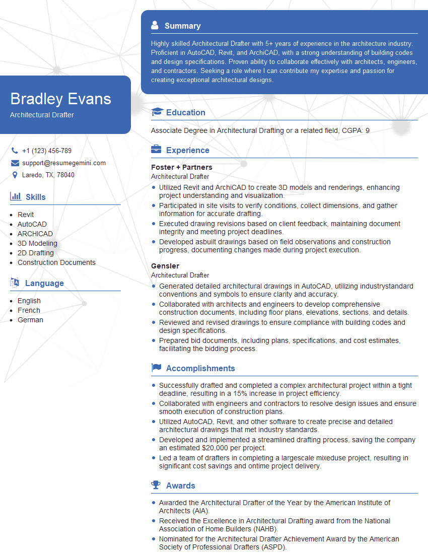
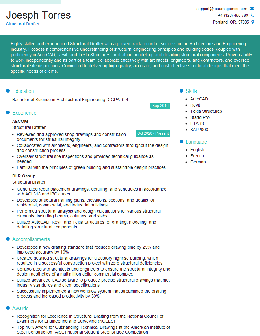
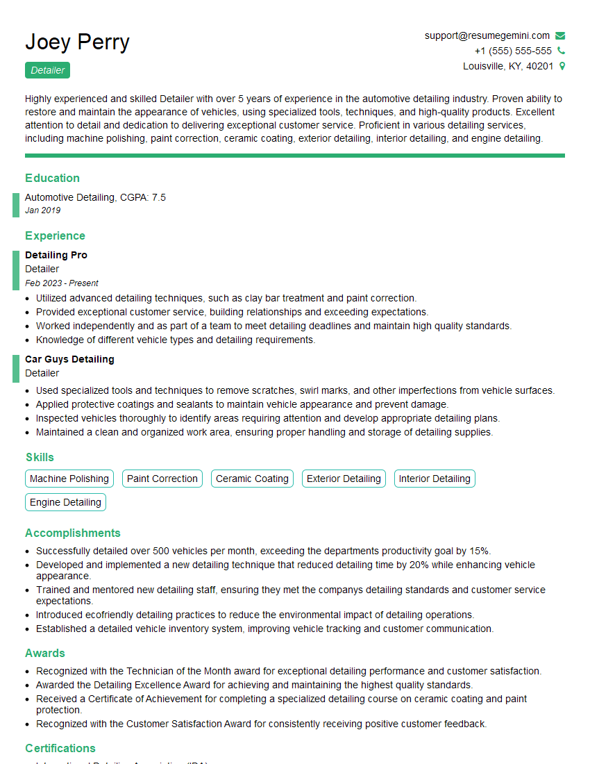
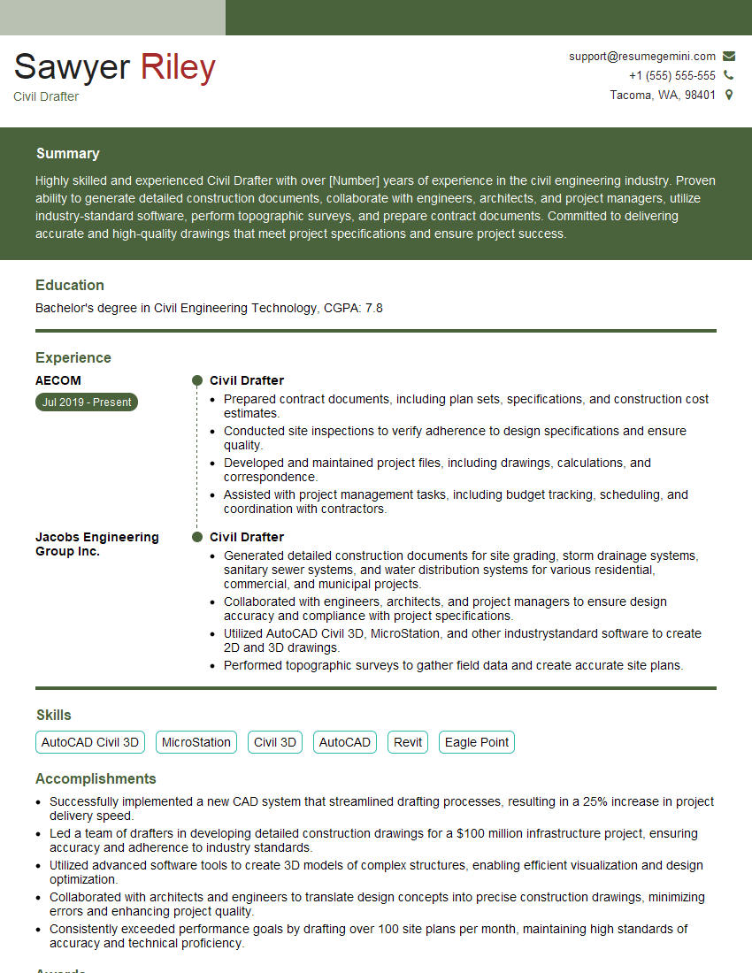
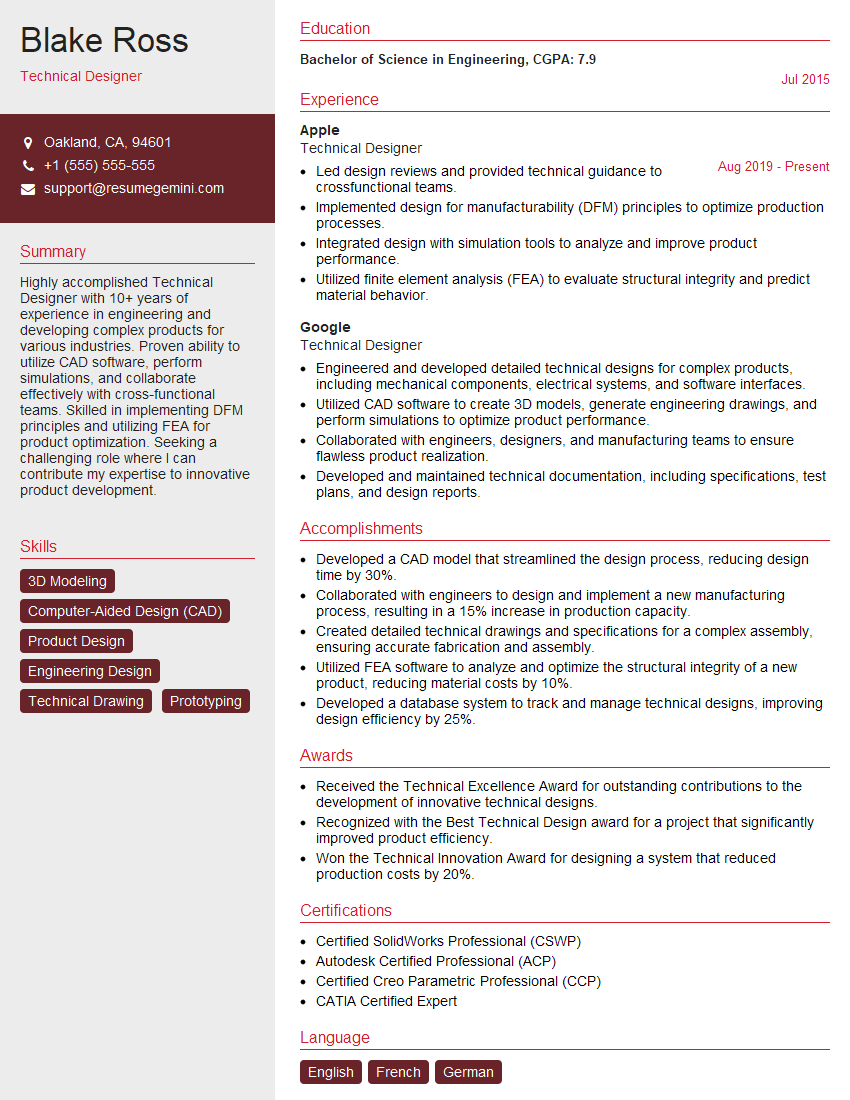
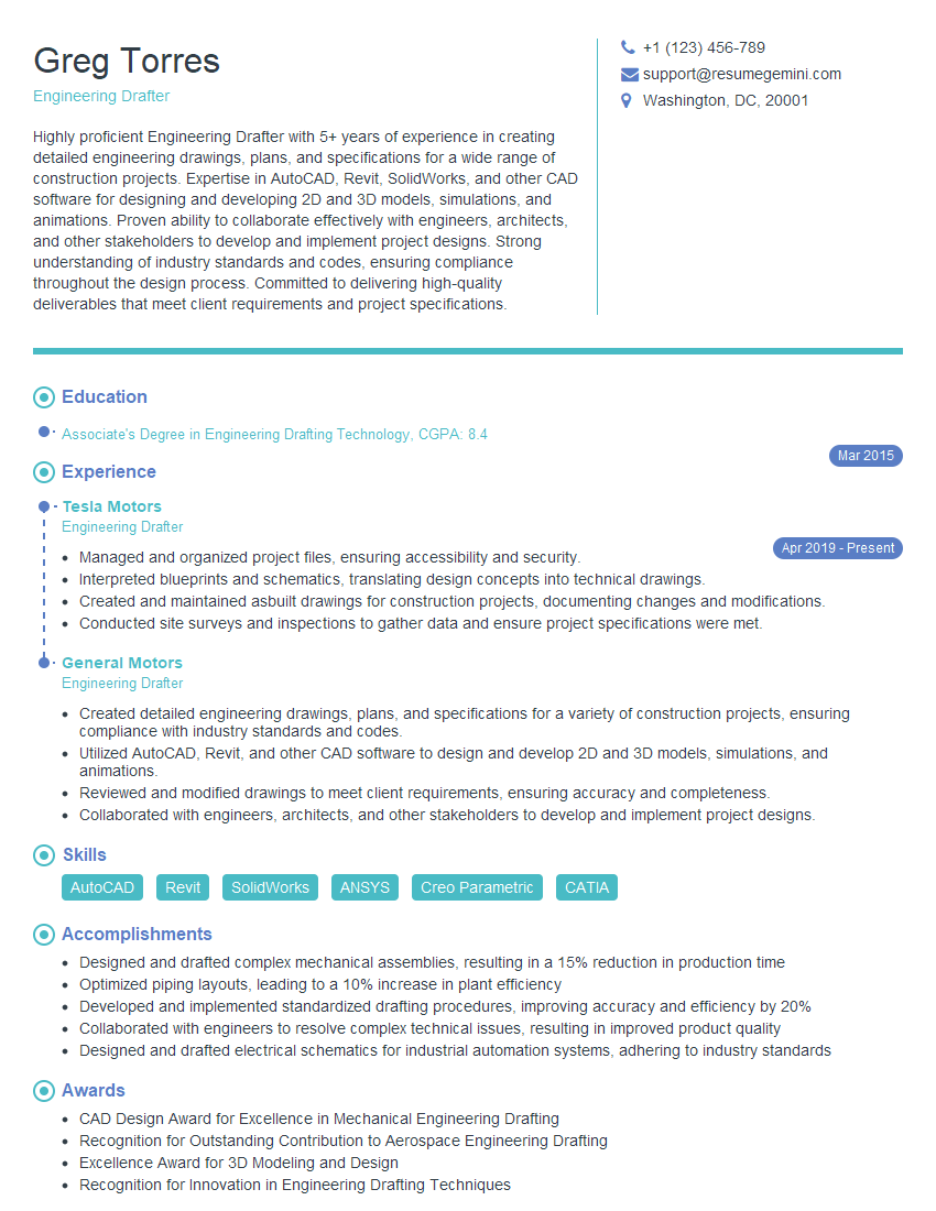
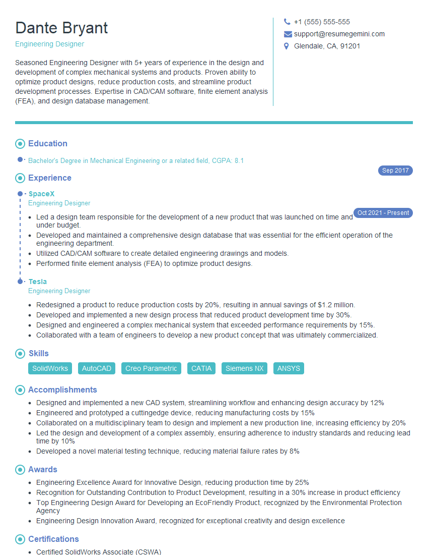
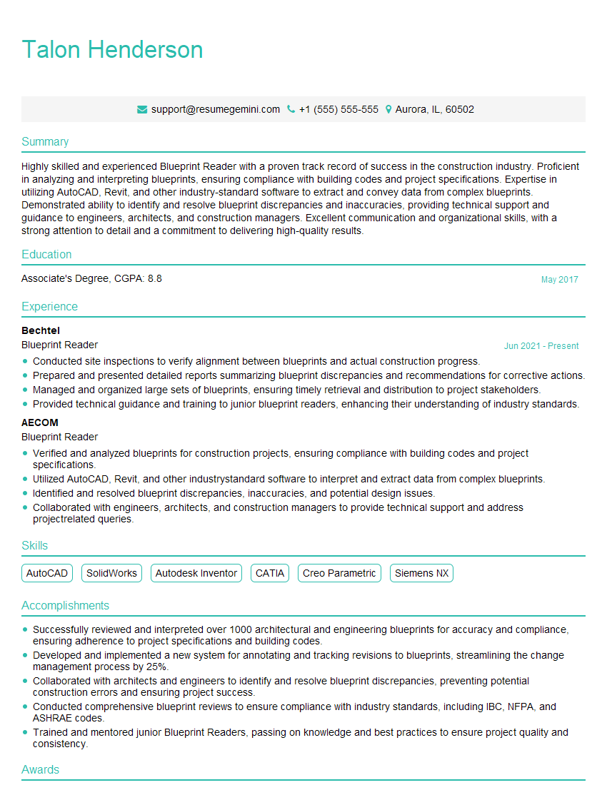
Mastering Blueprint Interpretation and Detailing is crucial for career advancement in architecture, construction, and engineering. A strong understanding of these skills opens doors to higher-paying roles with increased responsibility. To maximize your job prospects, it’s essential to create an ATS-friendly resume that effectively highlights your abilities. ResumeGemini is a trusted resource that can help you build a professional, impactful resume, ensuring your qualifications stand out to potential employers. Examples of resumes tailored to Blueprint Interpretation and Detailing are available to further guide you.
Explore more articles
Users Rating of Our Blogs
Share Your Experience
We value your feedback! Please rate our content and share your thoughts (optional).
What Readers Say About Our Blog
Hello,
We found issues with your domain’s email setup that may be sending your messages to spam or blocking them completely. InboxShield Mini shows you how to fix it in minutes — no tech skills required.
Scan your domain now for details: https://inboxshield-mini.com/
— Adam @ InboxShield Mini
Reply STOP to unsubscribe
Hi, are you owner of interviewgemini.com? What if I told you I could help you find extra time in your schedule, reconnect with leads you didn’t even realize you missed, and bring in more “I want to work with you” conversations, without increasing your ad spend or hiring a full-time employee?
All with a flexible, budget-friendly service that could easily pay for itself. Sounds good?
Would it be nice to jump on a quick 10-minute call so I can show you exactly how we make this work?
Best,
Hapei
Marketing Director
Hey, I know you’re the owner of interviewgemini.com. I’ll be quick.
Fundraising for your business is tough and time-consuming. We make it easier by guaranteeing two private investor meetings each month, for six months. No demos, no pitch events – just direct introductions to active investors matched to your startup.
If youR17;re raising, this could help you build real momentum. Want me to send more info?
Hi, I represent an SEO company that specialises in getting you AI citations and higher rankings on Google. I’d like to offer you a 100% free SEO audit for your website. Would you be interested?
Hi, I represent an SEO company that specialises in getting you AI citations and higher rankings on Google. I’d like to offer you a 100% free SEO audit for your website. Would you be interested?
good
