Interviews are more than just a Q&A session—they’re a chance to prove your worth. This blog dives into essential Electrical Design (Power, Control, Lighting) interview questions and expert tips to help you align your answers with what hiring managers are looking for. Start preparing to shine!
Questions Asked in Electrical Design (Power, Control, Lighting) Interview
Q 1. Explain the difference between AC and DC power.
The fundamental difference between AC (Alternating Current) and DC (Direct Current) lies in the direction of electron flow. In DC, electrons flow consistently in one direction, like water flowing downhill in a continuous stream. This results in a constant voltage and current. Think of a battery – it provides a steady DC voltage.
AC, on the other hand, is characterized by electrons that periodically change direction, oscillating back and forth. Imagine a seesaw – it moves up and down, and the flow of electrons is similarly alternating. This results in a voltage and current that vary sinusoidally over time, with a specific frequency (e.g., 50Hz or 60Hz). Our household power is typically AC.
This difference has significant implications in applications. DC is often preferred for low-voltage electronics and battery-powered devices due to its simplicity and ease of use. AC, however, is more efficient for long-distance transmission due to the ease of stepping voltage up and down using transformers, minimizing energy loss during transmission.
Q 2. Describe your experience with different types of transformers.
My experience encompasses a wide range of transformer types, including step-up, step-down, isolation, autotransformers, and specialized transformers like current transformers (CTs) and potential transformers (PTs). I’ve worked extensively with both power transformers, handling kilovolt-ampere (kVA) ratings in the hundreds, and smaller signal transformers used in control circuits.
For example, in a recent project involving a large industrial facility, I specified and oversaw the installation of three-phase step-down transformers to reduce the high-voltage supply from the utility grid to a usable voltage for the facility’s machinery. The selection involved careful consideration of kVA rating, voltage ratios, efficiency, and cooling requirements to ensure optimal performance and safety. I also have experience with using CTs and PTs in protection schemes, providing accurate measurements for relaying purposes. In another project, I designed a custom isolation transformer for a sensitive medical device to prevent ground loops and ensure electrical safety.
Q 3. What are the key considerations for designing a lighting system for an industrial facility?
Designing a lighting system for an industrial facility requires a multifaceted approach prioritizing safety, efficiency, and productivity. Key considerations include:
- Illuminance Levels: Meeting the required illuminance levels (measured in lux) for different work areas, based on industry standards and task requirements. This varies significantly between areas like assembly lines and storage areas.
- Lighting Type: Selecting appropriate lighting fixtures like high-bay, low-bay, or linear lights, considering factors like mounting height, area size, and energy efficiency.
- Energy Efficiency: Using energy-efficient lighting technologies like LEDs with high lumens per watt (lpw) to minimize operating costs and reduce environmental impact. Implementing lighting controls like occupancy sensors and daylight harvesting are crucial.
- Color Rendering Index (CRI): Ensuring adequate CRI to accurately represent colors, crucial for tasks involving color matching or quality control. A higher CRI is generally preferred in industrial settings.
- Safety: Designing for safety involves using appropriate protection against dust, moisture, and impact, selecting fixtures with sufficient ingress protection (IP) ratings. Emergency lighting and appropriate lighting for escape routes are also essential.
- Maintenance: Choosing fixtures with easy access for maintenance and lamp replacement to minimize downtime. This includes considering the height of the fixtures and the ease of reaching them.
Q 4. How do you select appropriate conductors for a power distribution system?
Selecting appropriate conductors involves a careful analysis of several factors, mainly current carrying capacity, voltage drop, and safety considerations. The process starts with calculating the load current for each circuit. The ampacity (current carrying capacity) of the conductor must be higher than the calculated load current, taking into account ambient temperature and installation conditions (e.g., conduit fill). Voltage drop needs to be within acceptable limits, usually less than 3% across the entire circuit length to ensure proper equipment operation. I often use specialized software for this purpose, which simplifies the calculations.
Once the required ampacity is determined, I consult the National Electrical Code (NEC) or other relevant standards to determine the appropriate conductor size and material (copper or aluminum). Safety is paramount, so factors like insulation rating, short-circuit withstand capability, and grounding requirements are considered. The choice between copper and aluminum depends on cost and the specific application. Copper has higher conductivity, while aluminum is cheaper and lighter.
For instance, selecting conductors for a high-current motor would involve significantly larger gauge wires compared to those used for lighting circuits, ensuring sufficient capacity to handle the motor’s startup current and potential surges.
Q 5. Explain your understanding of grounding and earthing.
Grounding and earthing are often used interchangeably, but there’s a subtle difference. Earthing refers to connecting the non-current-carrying metallic parts of an electrical installation to the earth, providing a low-impedance path for fault currents. This protects against electric shock and equipment damage. Imagine a safety net; earthing acts as the net, preventing hazardous voltages from appearing on exposed metal parts.
Grounding is broader, encompassing the connection of electrical systems and equipment to the earth (earthing) and providing a common reference point for voltage measurements and signal return paths. It ensures voltage stability and signal integrity. A good grounding system is the cornerstone of electrical safety and efficient operation.
In practice, both are crucial. A properly designed grounding system minimizes the risk of electric shock by providing a path for fault currents to flow safely to the earth, preventing dangerous voltage buildup on metal enclosures. It also ensures the proper operation of protective devices such as ground fault circuit interrupters (GFCIs) and ensures the safety of personnel and equipment. Improper grounding can lead to serious accidents and equipment damage.
Q 6. Describe your experience with various types of protective relays.
My experience with protective relays covers a wide range, including overcurrent relays, differential relays, distance relays, and more specialized relays like those for busbar protection and generator protection. I’ve worked extensively with both electromechanical and numerical relays, the latter being more prevalent in modern systems due to their enhanced capabilities and flexibility.
For instance, I’ve used overcurrent relays extensively in power distribution systems to protect against faults caused by excessive currents. These relays are often coordinated to ensure that only the necessary sections of the system trip during a fault, minimizing disruption. I’ve also used differential relays in transformer and motor protection, providing highly sensitive detection of internal faults. In a recent project, we implemented a sophisticated protection scheme using numerical relays with advanced communication capabilities, allowing for remote monitoring and control of the system’s protection.
The selection of a specific relay type depends on the application and the specific protection requirements. Factors such as the type of equipment being protected, the fault characteristics, and the desired level of protection are all carefully considered.
Q 7. What are your preferred methods for troubleshooting electrical issues?
My troubleshooting methodology is systematic and follows a structured approach to efficiently isolate and resolve electrical issues. It begins with safety – always ensuring the power is disconnected and locked out before starting any work. Then, I follow these steps:
- Gather Information: Start by collecting information about the problem. This includes understanding the symptoms, when the problem started, and any preceding events. I often rely on operator logs and historical data for clues.
- Visual Inspection: A thorough visual inspection is crucial, looking for obvious signs of damage, loose connections, overheating, or other abnormalities. Sometimes a simple loose wire is the culprit!
- Testing and Measurement: This is where I use various testing instruments such as multimeters, clamp meters, and insulation testers to measure voltages, currents, resistances, and insulation integrity. Data loggers are also employed to capture real-time data.
- Systematic Elimination: Based on the test results, I systematically eliminate possible causes, narrowing down the source of the problem. This often requires a good understanding of the electrical system’s schematics and operating principles.
- Corrective Action: Once the root cause is identified, I implement the necessary repairs or replacements. This is always followed by thorough testing and verification to ensure the problem is resolved.
- Documentation: Detailed documentation of the troubleshooting process, including findings, actions taken, and verification results, is crucial for future reference and maintenance planning.
This structured approach ensures thorough analysis and avoids unnecessary work by focusing on the most probable causes first. Every step is documented, so the solution is readily available if the same issue arises again.
Q 8. Explain the concept of power factor correction.
Power factor correction (PFC) is a technique used to improve the efficiency of electrical systems by reducing the reactive power component. Imagine electricity as a river flowing to your home. The real power is the water actually turning the turbine (doing useful work), while reactive power is like water sloshing back and forth without doing any work. A low power factor means more “sloshing” (reactive power) and less efficient use of the electricity.
In AC circuits, inductive loads like motors and transformers draw reactive power, causing the current to lag behind the voltage. This low power factor leads to increased current flow for the same amount of real power, resulting in higher energy costs and increased stress on equipment. PFC aims to bring the power factor closer to 1 (unity), minimizing the reactive power component and improving efficiency.
This is achieved by adding capacitor banks to the circuit. Capacitors draw leading reactive power, which counteracts the lagging reactive power from inductive loads. By carefully calculating the required capacitance, we can significantly improve the power factor and optimize the system’s performance. For example, in a large industrial facility with numerous motors, implementing PFC can lead to significant cost savings on electricity bills and reduced equipment wear.
Q 9. How do you calculate voltage drop in a circuit?
Voltage drop is the reduction in voltage across a circuit element due to its impedance. Think of it like water pressure decreasing as it flows through a long pipe. The longer and narrower the pipe, the greater the pressure drop. Similarly, the longer the wire and the higher its resistance, the greater the voltage drop.
We calculate voltage drop using Ohm’s Law (V = IR) and the formula for the resistance of a conductor (R = ρL/A), where:
- V = voltage drop
- I = current
- R = resistance of the conductor
- ρ = resistivity of the conductor material
- L = length of the conductor
- A = cross-sectional area of the conductor
In practice, we often use simplified formulas to account for the total resistance of the circuit, including the wire’s resistance. For example, in a single-phase circuit, the voltage drop (ΔV) can be calculated as: ΔV = 2 * I * R * L / 1000 (where L is in meters and R is in ohms/1000m). This calculation ensures sufficient voltage reaches the load to operate correctly and prevents overheating due to excessive current.
Q 10. What is your experience with different types of motor control systems?
My experience encompasses various motor control systems, including:
- Direct On-Line (DOL) starters: Simple and cost-effective, but can cause high inrush currents.
- Star-Delta starters: Reduce starting current compared to DOL starters, suitable for medium-sized motors.
- Autotransformer starters: Offer smooth starting and reduced inrush currents, ideal for large motors.
- Variable Frequency Drives (VFDs): Provide precise speed control, energy efficiency, and reduced mechanical wear. I have extensive experience designing and implementing VFD systems for various applications, from conveyor belts to pumps, optimizing parameters for specific motor characteristics and operational requirements.
- Soft starters: Offer gradual motor acceleration, reducing mechanical stress and extending motor lifespan.
I’ve also worked with specialized motor control systems like those used in servo-mechanisms and stepper motors for precise positioning and motion control in automated processes. Each system’s selection depends on factors such as motor size, load characteristics, and the desired level of control.
Q 11. Describe your experience with programmable logic controllers (PLCs).
I possess extensive experience programming and implementing PLCs across various industrial settings. My proficiency includes ladder logic programming, structured text, and function block diagrams. I’ve worked with different PLC brands, including Allen-Bradley, Siemens, and Schneider Electric, adapting my programming style to meet the specific requirements of each system.
My experience extends beyond basic programming to encompass the design, implementation, and troubleshooting of complex PLC-based control systems. This includes creating HMI (Human-Machine Interface) screens for intuitive operator interaction, integrating PLCs with other industrial automation components, and designing safety circuits conforming to relevant standards. For instance, I successfully developed a PLC-based control system for a packaging line, optimizing production speed while ensuring safe operation.
Q 12. Explain your understanding of SCADA systems.
SCADA (Supervisory Control and Data Acquisition) systems provide real-time monitoring and control of industrial processes. Think of it as a central nervous system for a large facility. It collects data from various field devices, like sensors and actuators, through communication protocols like Modbus, Profibus, or Ethernet/IP. This data is then processed and presented to operators through a centralized interface, allowing them to monitor system performance and make adjustments as needed.
My experience with SCADA systems includes designing, configuring, and maintaining systems for various applications, such as water treatment plants, power generation facilities, and manufacturing processes. I have worked with different SCADA software packages, such as Wonderware InTouch and GE Proficy iFIX, and have a thorough understanding of database integration and alarm management. A recent project involved integrating a new SCADA system into an existing facility, improving real-time monitoring capabilities and enhancing operational efficiency.
Q 13. What are your preferred software tools for electrical design?
My preferred software tools for electrical design are:
- AutoCAD Electrical: For schematic design, panel layouts, and wire lists. Its intelligent components and automation features significantly reduce design time and errors.
- ETAP: For power system analysis, short-circuit calculations, and protective relay coordination studies. Its robust simulation capabilities allow for thorough verification and optimization of power systems.
- EPLAN Electric P8: For creating comprehensive electrical documentation, including wiring diagrams, terminal layouts, and cable schedules. Its centralized database ensures consistency and ease of management.
- PLC programming software (specific to the PLC brand): Such as RSLogix 5000 (Allen-Bradley), TIA Portal (Siemens), or Unity Pro (Schneider Electric).
I also utilize Microsoft Office Suite for documentation and reporting, and specialized software for specific tasks, adapting my tool selection to the project’s demands.
Q 14. How do you ensure compliance with relevant electrical codes and standards?
Ensuring compliance with electrical codes and standards is paramount in my work. I am familiar with the National Electrical Code (NEC), IEEE standards, and other relevant international standards. My approach involves several key steps:
- Thorough design review: Each design is reviewed meticulously against the applicable codes and standards at multiple stages.
- Calculations and simulations: Detailed calculations and simulations are performed to verify that the design meets safety and performance requirements.
- Proper documentation: Comprehensive documentation, including calculations, diagrams, and test reports, is maintained to demonstrate compliance.
- Regular updates: I stay current with the latest updates and revisions to the relevant codes and standards, ensuring that my designs remain compliant.
- Third-party review (when needed): For critical projects, I engage independent third-party review to ensure compliance and eliminate potential risks.
Maintaining compliance is not just a matter of following rules; it’s a commitment to safety and reliability. It’s crucial for protecting people, equipment, and the environment.
Q 15. Describe your experience with electrical safety regulations.
Electrical safety is paramount in my work. My experience encompasses a thorough understanding and strict adherence to regulations like the National Electrical Code (NEC) in the US, or equivalent standards internationally. This includes familiarity with arc flash hazard analysis, lockout/tagout procedures, and grounding techniques. For instance, on a recent project involving a high-voltage substation upgrade, we meticulously followed NFPA 70E guidelines to ensure the safety of our personnel and prevent arc flash incidents. This involved detailed risk assessments, the use of appropriate personal protective equipment (PPE), and the implementation of stringent permit-to-work systems. Beyond the code, I also incorporate best practices for preventing electrical shock, fire hazards, and equipment damage, always prioritizing worker safety and public safety.
Specifically, I’m proficient in:
- NEC/IEC standards: Understanding and applying relevant sections to ensure compliance.
- Arc flash hazard analysis: Conducting studies to determine the potential for arc flash incidents and implementing appropriate mitigation measures.
- Lockout/Tagout (LOTO) procedures: Implementing safe work practices to de-energize equipment before maintenance or repairs.
- Grounding and bonding: Ensuring proper grounding to minimize electrical shock hazards.
Career Expert Tips:
- Ace those interviews! Prepare effectively by reviewing the Top 50 Most Common Interview Questions on ResumeGemini.
- Navigate your job search with confidence! Explore a wide range of Career Tips on ResumeGemini. Learn about common challenges and recommendations to overcome them.
- Craft the perfect resume! Master the Art of Resume Writing with ResumeGemini’s guide. Showcase your unique qualifications and achievements effectively.
- Don’t miss out on holiday savings! Build your dream resume with ResumeGemini’s ATS optimized templates.
Q 16. How do you manage electrical projects with multiple stakeholders?
Managing electrical projects with multiple stakeholders requires excellent communication and collaboration skills. I employ a structured approach, beginning with clearly defining project goals, scope, and timelines, ensuring all stakeholders are on the same page from the start. I use tools like project management software (e.g., MS Project, Primavera P6) to track progress, manage resources, and maintain transparency. Regular meetings, detailed reports, and proactive communication are crucial. For example, on a recent hospital renovation project, we had architects, contractors, building management, and healthcare staff as stakeholders. I established a collaborative platform using shared documents and regular progress meetings to ensure everyone was informed and their concerns addressed promptly. Addressing potential conflicts early, through open dialogue and compromise, is key to maintaining a positive working relationship and project success. Active listening and conflict resolution skills are vital in navigating differing opinions and ensuring a consensus.
Q 17. Explain your experience with different types of lighting fixtures and their applications.
My experience with lighting fixtures spans a wide range, including incandescent, fluorescent, LED, high-intensity discharge (HID), and emergency lighting. Each type has unique applications and advantages. Incandescent lights, while simple, are energy-inefficient. Fluorescent lights are more energy-efficient but contain mercury and require proper disposal. LEDs are now dominant due to high energy efficiency, long lifespan, and diverse color temperature options. HID lamps like metal halide or high-pressure sodium are suitable for high-intensity applications such as sports fields or large parking lots, but they have longer startup times and may not be suitable for frequently switched applications. I’ve designed lighting systems incorporating various fixture types to optimize performance for diverse environments. For example, I specified LED downlights for office spaces, energy-efficient linear fluorescents for warehouses, and high-pressure sodium lamps for outdoor parking areas, always considering factors such as light distribution, color rendering, and energy efficiency.
Further, I’m familiar with various fixture mounting types (recessed, surface mounted, pendant) and the selection criteria for each, considering factors such as ceiling height, aesthetics, and accessibility.
Q 18. Describe your understanding of lighting design principles, such as illuminance and luminance.
Illuminance and luminance are fundamental lighting design principles. Illuminance (measured in lux or footcandles) refers to the amount of light falling on a surface, while luminance (measured in candelas per square meter or nits) refers to the amount of light emitted or reflected from a surface. Understanding the difference is crucial for creating effective lighting designs. For example, a high illuminance level might be necessary in a task-oriented area like a surgery room, but a high luminance could be undesirable due to glare. In designing a space, I consider both parameters in conjunction. Other critical design principles include color rendering index (CRI), which indicates how accurately colors appear under a given light source, and uniformity of illumination, ensuring even light distribution across the space to avoid harsh shadows or dark spots. These principles are crucial in creating environments that meet visual comfort and task performance requirements. I use lighting design software to simulate lighting scenarios, optimize illuminance levels, and ensure proper luminance distribution, minimizing glare and ensuring visual comfort.
Q 19. How do you design lighting systems to meet energy efficiency standards?
Designing energy-efficient lighting systems involves several strategies. First, selecting energy-efficient light sources like LEDs is crucial. Secondly, optimizing lighting controls plays a significant role. This could involve using occupancy sensors to automatically switch off lights in unoccupied areas, daylight harvesting systems to supplement natural light, and dimming controls to adjust light levels based on need. For instance, in a large office building, we implemented a lighting control system that combined occupancy sensors, daylight harvesting, and a centralized dimming system, resulting in a significant reduction in energy consumption. Thirdly, proper fixture selection is crucial, considering factors like light distribution, efficiency, and thermal management. Lastly, regular maintenance and replacement of inefficient lamps help maintain optimal energy performance. I also consider the use of energy modeling software to predict energy savings and optimize lighting designs before implementation.
Q 20. Explain your experience with different types of control systems for lighting.
I have experience with various lighting control systems, including simple on/off switches, dimming systems (0-10V, DMX, DALI), and intelligent control systems. Simple on/off switches are cost-effective but lack flexibility. Dimming systems allow for adjusting light levels to meet varying needs, improving energy efficiency and visual comfort. 0-10V is a common analog dimming protocol, while DMX and DALI are digital protocols offering greater control and flexibility, particularly in larger installations. For example, in a retail environment, we used a DALI system to control individual light fixtures, allowing for dynamic lighting scenes to be created and scheduled to match the store’s operational hours and promotional events. This provided enhanced visual merchandising while optimizing energy consumption. My experience includes designing, installing, and commissioning these systems, ensuring seamless integration and reliable performance.
Q 21. Describe your experience with building automation systems (BAS).
Building Automation Systems (BAS) integrate various building systems, including lighting, HVAC, security, and fire protection, under a centralized control platform. My experience with BAS involves integrating lighting systems into broader building management strategies. This allows for comprehensive monitoring and control of lighting, optimizing energy efficiency across the entire building. For example, I worked on a project where we integrated the lighting system with the HVAC system to dynamically adjust lighting levels based on occupancy and environmental conditions, further optimizing energy savings. BAS allows for remote monitoring, automated scheduling, and fault detection, enhancing building operation efficiency and occupant comfort. I’m proficient in working with various BAS platforms and protocols, ensuring seamless integration and reliable operation of the entire building management system. Data analysis from the BAS is also critical for identifying areas for improvement and further optimizing energy efficiency.
Q 22. How do you design a power distribution system for a large commercial building?
Designing a power distribution system for a large commercial building is a complex undertaking requiring a systematic approach. It starts with a thorough understanding of the building’s load profile – the anticipated power demands of various areas like offices, HVAC systems, elevators, and lighting. This involves analyzing the building plans, understanding the intended use of each space, and estimating power consumption for each appliance and system.
Next, we determine the service entrance capacity, which is the maximum power the building can draw from the utility grid. This dictates the size of the main switchboard and the distribution transformers. The system is then designed to branch out from the main switchboard, typically using a combination of panelboards and sub-panelboards to distribute power efficiently throughout the building. Each panelboard serves a specific area or floor, allowing for better control and isolation in case of faults.
Careful consideration is given to voltage levels, conductor sizing (based on current carrying capacity and voltage drop calculations), grounding and bonding, and safety regulations (like the NEC in the US). We use specialized software for load flow and short-circuit analysis to ensure the system can handle peak loads and withstand potential faults without causing damage or endangering occupants. Finally, the design incorporates redundancy and protection devices like circuit breakers, fuses, and surge protection to ensure reliability and safety.
For instance, in a recent project for a large office complex, we utilized a sophisticated computer model to simulate various load scenarios and optimize the placement of transformers and switchgear to minimize voltage drop and energy losses. This resulted in significant cost savings and improved energy efficiency.
Q 23. Explain your experience with different types of power generation systems.
My experience encompasses various power generation systems, ranging from traditional fossil fuel-based plants to renewable energy sources. I’ve worked on projects involving natural gas combined-cycle power plants, where the efficiency is boosted by using the waste heat from gas turbines to generate steam for steam turbines. I’m also familiar with coal-fired plants, although their use is decreasing due to environmental concerns. My experience extends to renewable sources such as solar PV (photovoltaic) systems, wind turbines, and hydroelectric plants.
In the renewable energy space, I’ve been involved in designing the grid integration aspects of large-scale solar farms, including the design of the collection systems, inverters, and connection to the transmission network. Working with wind turbines involves considerations for the fluctuating nature of the power generation and the need for effective energy storage or grid management solutions. With hydroelectric projects, the focus is on the efficient design of the hydro-generators and the associated power transmission infrastructure.
Each system has its own unique challenges. For example, solar PV systems require careful consideration of the solar irradiance levels and the orientation of the panels to maximize energy output. Wind turbine projects need detailed wind resource assessment and consideration for the environmental impact on avian populations. My work always involves a careful balance between technical feasibility, economic viability, and environmental sustainability.
Q 24. Describe your understanding of load flow analysis.
Load flow analysis is a crucial part of power system design. It’s a steady-state analysis that determines the voltage magnitude and phase angle at each bus (node) in a power system under a given load condition. This analysis is essential for determining power flows in transmission lines and transformers, identifying potential voltage violations, and assessing the system’s stability.
We typically use specialized software packages that employ iterative methods (like Gauss-Seidel or Newton-Raphson) to solve the power flow equations. The input data includes the system topology, impedance values of transmission lines and transformers, and the active and reactive power loads at each bus. The output provides a comprehensive picture of the system’s behavior under the given load condition, allowing us to identify potential bottlenecks or areas requiring improvement.
For example, in a recent project, load flow analysis helped us identify a potential voltage sag in a remote part of the network during peak load. This analysis allowed us to proactively implement solutions like capacitor banks or voltage regulators to prevent the voltage sag from affecting critical equipment.
Understanding load flow analysis is critical in ensuring reliable and efficient power distribution. It provides the essential data needed for planning future expansions and upgrades to the power system.
Q 25. How do you manage electrical projects within budget and schedule constraints?
Managing electrical projects within budget and schedule constraints requires meticulous planning, proactive monitoring, and effective communication. We start by developing a detailed project schedule using tools like Gantt charts, identifying critical path activities and setting realistic milestones. This schedule is linked to a comprehensive budget, breaking down costs for materials, labor, and other resources.
Regular progress meetings are held with the project team and stakeholders to track progress against the schedule and budget. Any deviations are immediately addressed through proactive mitigation strategies, like adjusting the schedule, reallocating resources, or negotiating with suppliers. We utilize project management software to track progress, manage documents, and facilitate communication. Value engineering techniques are employed to explore cost-effective alternatives without compromising the quality or safety of the design.
For instance, in one project, we identified a potential cost overrun due to a delay in material delivery. By working closely with the supplier and exploring alternative materials, we managed to mitigate the delay and stay within the budget.
Effective change management is essential. Any changes to the scope of work are thoroughly assessed for their impact on the schedule and budget before being implemented. This ensures transparency and accountability throughout the project lifecycle.
Q 26. Explain your experience with fault current calculations.
Fault current calculations are essential for selecting appropriate protective devices like circuit breakers and fuses. These calculations determine the magnitude of current that would flow during a fault (short circuit) in the system. This information is critical for ensuring the safety of personnel and equipment.
The calculations are based on the system impedance, including the source impedance, transformer impedance, and the impedance of the conductors. We employ specialized software that uses symmetrical component analysis to determine the fault current under various fault types (e.g., three-phase, single-line-to-ground). The results are used to select protective devices with sufficient interrupting capacity to safely clear the fault.
For example, if the fault current calculation shows a value exceeding the interrupting capacity of an existing circuit breaker, we would need to replace it with a higher-rated breaker or implement additional protective measures.
Accurate fault current calculations are critical for ensuring the system’s safety and reliability.
Q 27. Describe your experience with short circuit analysis.
Short circuit analysis is a crucial part of electrical system design. It’s used to determine the magnitude and duration of fault currents that would flow during various short circuit scenarios within the electrical system.
This analysis involves applying circuit theory principles, particularly using the concept of symmetrical components to simplify the calculation of fault currents for different types of faults (like three-phase, line-to-ground, or line-to-line faults). The process often involves software tools that can model complex electrical networks and calculate the resulting fault currents at various points within the system.
The results of short circuit analysis inform the selection of protective devices such as circuit breakers and fuses, ensuring they have sufficient interrupting capacity to clear faults safely and prevent damage to equipment or injury to personnel. It also aids in the design of grounding systems to minimize the impact of ground faults.
For instance, in a recent project, short circuit analysis revealed that an existing substation transformer had an insufficient interrupting capacity for a particular fault scenario. This analysis led to the installation of a larger, appropriately rated transformer to ensure the system’s safety.
Q 28. What are your strategies for working effectively in a team environment on electrical design projects?
Effective teamwork is paramount in electrical design projects. My strategy involves clear communication, active listening, and a collaborative approach. I believe in fostering an environment where everyone feels comfortable sharing their ideas and concerns. This includes regular team meetings, where we discuss project progress, address challenges, and ensure everyone is on the same page.
I actively participate in brainstorming sessions, encouraging diverse perspectives and leveraging the expertise of each team member. I also advocate for using collaborative software platforms that enable seamless document sharing and real-time updates. Conflict resolution is handled through open and respectful communication, focusing on finding mutually acceptable solutions. I value the contributions of each team member and strive to create a positive and supportive team environment.
For example, on a recent project, a disagreement arose regarding the best approach to a specific design challenge. Through a facilitated discussion, we explored all options, analyzed their pros and cons, and collaboratively decided on the optimal solution, ensuring everyone understood the rationale behind the decision.
I believe that a strong team, built on trust and mutual respect, is essential for delivering successful and innovative electrical design projects.
Key Topics to Learn for Electrical Design (Power, Control, Lighting) Interview
- Power Systems Design: Understanding power distribution systems, including transformers, circuit breakers, and protective relays. Practical application: Designing a power distribution system for a commercial building, considering load calculations and safety regulations.
- Control Systems Design: Familiarity with programmable logic controllers (PLCs), motor control circuits, and industrial automation systems. Practical application: Troubleshooting a malfunctioning PLC program in a manufacturing facility.
- Lighting Design: Knowledge of lighting calculations, illumination levels, energy-efficient lighting technologies (LEDs), and lighting control systems. Practical application: Designing an energy-efficient lighting system for a hospital, considering patient comfort and safety.
- Electrical Codes and Standards: Proficiency in relevant electrical codes (NEC, IEC) and safety standards. Practical application: Ensuring compliance with building codes during the design and implementation of electrical systems.
- Electrical Drawings and Schematics: Ability to interpret and create clear and accurate electrical drawings and schematics using AutoCAD or similar software. Practical application: Creating detailed drawings for a complex electrical system for review and construction.
- Power System Analysis: Understanding of load flow studies, fault analysis, and power system stability. Practical application: Analyzing the impact of adding new loads to an existing power system.
- Renewable Energy Systems: Knowledge of solar PV systems, wind turbines, and other renewable energy technologies and their integration into power grids. Practical application: Designing a hybrid power system incorporating renewable energy sources.
- Problem-solving and Troubleshooting: Demonstrating the ability to diagnose and resolve electrical system issues effectively. Practical application: Describing your approach to troubleshooting a faulty circuit in a residential setting.
Next Steps
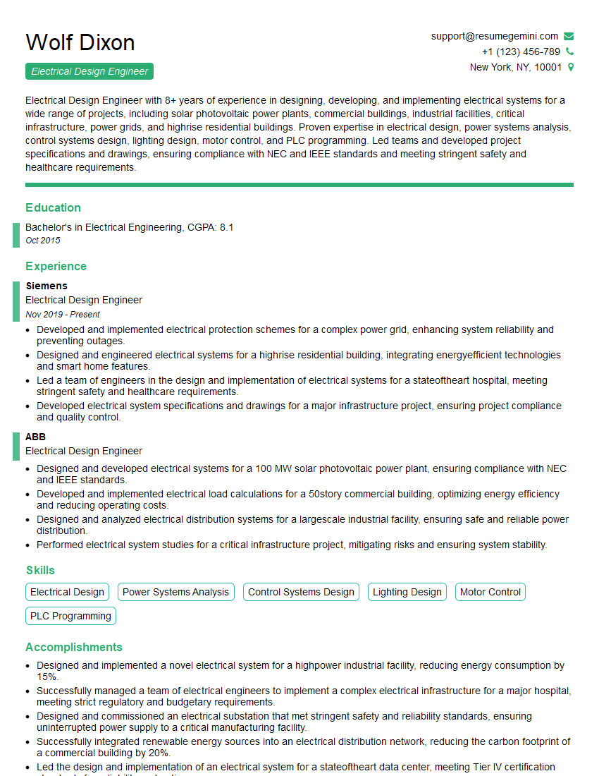
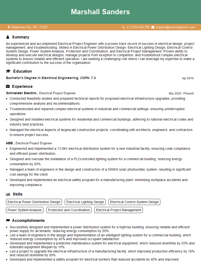
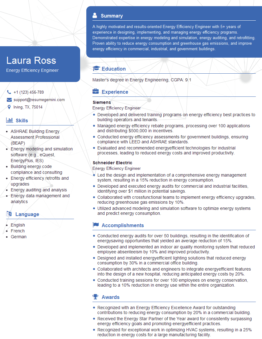
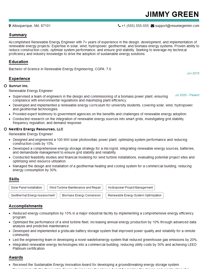
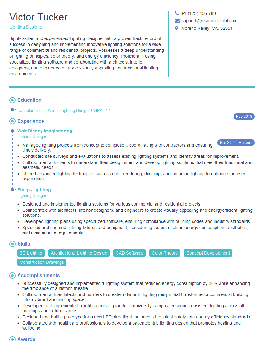
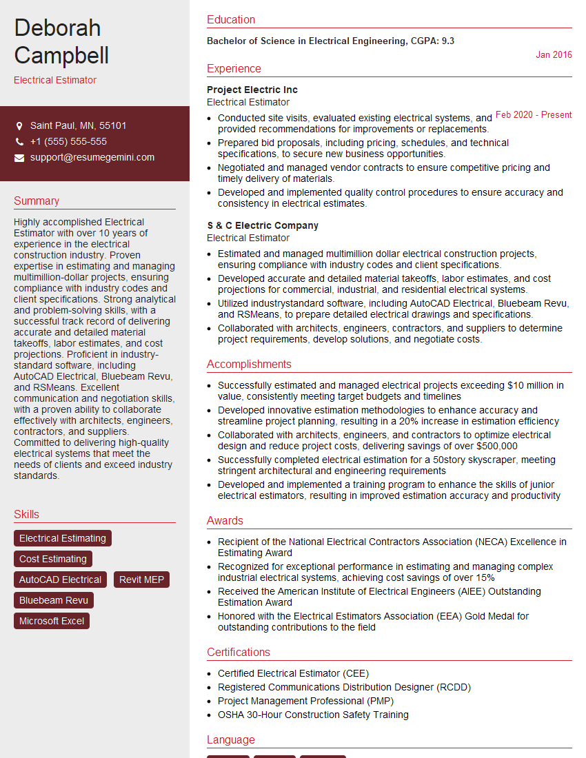
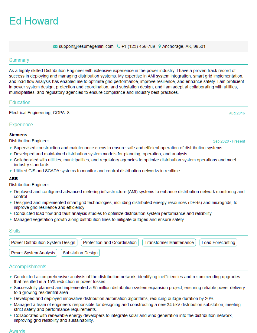
Mastering Electrical Design (Power, Control, Lighting) is crucial for a successful and rewarding career, opening doors to diverse and challenging roles within the industry. A strong understanding of these areas will significantly enhance your job prospects and allow you to contribute meaningfully to innovative projects. To make the most of your job search, focus on crafting an ATS-friendly resume that highlights your skills and experience effectively. ResumeGemini is a trusted resource that can help you build a professional and impactful resume, designed to catch the attention of recruiters. Examples of resumes tailored to Electrical Design (Power, Control, Lighting) are available to help you get started.
Explore more articles
Users Rating of Our Blogs
Share Your Experience
We value your feedback! Please rate our content and share your thoughts (optional).
What Readers Say About Our Blog
Hi, I represent an SEO company that specialises in getting you AI citations and higher rankings on Google. I’d like to offer you a 100% free SEO audit for your website. Would you be interested?
good
