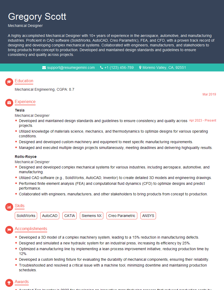
Interviews are opportunities to demonstrate your expertise, and this guide is here to help you shine. Explore the essential CAD and Engineering Software interview questions that employers frequently ask, paired with strategies for crafting responses that set you apart from the competition.
Questions Asked in CAD and Engineering Software Interview
Q 1. Explain the difference between 2D and 3D CAD modeling.
The core difference between 2D and 3D CAD modeling lies in the dimensionality of the designs. 2D CAD creates flat, two-dimensional representations, like blueprints or technical drawings. Think of it like drawing on a piece of paper – you can show length and width, but not depth or volume. 3D CAD, on the other hand, allows for the creation of three-dimensional models, representing length, width, *and* depth. This allows for a much more complete and realistic representation of the object, offering advantages in visualization, analysis, and manufacturing.
Example: A 2D drawing of a house would show the floor plan and elevations, but wouldn’t accurately represent the house’s volume or the relationships between different components. A 3D model of the same house, however, allows you to ‘walk through’ it virtually, analyze its structural integrity, and easily generate manufacturing instructions for each component.
In short, 2D is great for basic plans and documentation, while 3D provides a far more comprehensive and versatile design approach, vital for complex products or projects.
Q 2. What CAD software are you proficient in? List specific versions.
I’m proficient in several CAD software packages. My expertise spans various versions of Autodesk Inventor (specifically versions 2020-2024), SolidWorks (2019-2023), and AutoCAD (2018-2024). I also have working experience with Fusion 360 and Creo Parametric.
My proficiency extends beyond basic modeling; I’m comfortable using advanced features like simulation, rendering, and data management tools within these platforms. I can adapt quickly to new versions and functionalities as needed.
Q 3. Describe your experience with parametric modeling.
Parametric modeling is a cornerstone of modern CAD. It’s a way of creating models where features are defined by parameters – variables like dimensions, constraints, and relationships. Changes to one parameter automatically update the rest of the model, maintaining design integrity and saving significant time. It’s like having a smart blueprint that adjusts itself.
Example: Imagine designing a box. In parametric modeling, you define the length, width, and height as parameters. If you later decide to increase the length, the software automatically adjusts the overall dimensions, ensuring all aspects of the box remain consistent and appropriately sized.
My experience with parametric modeling includes using it extensively for designing complex assemblies, optimizing designs for manufacturing, and creating robust, easily modifiable models that adapt to changing requirements. This has significantly improved design efficiency and accuracy on numerous projects.
Q 4. How do you handle large CAD files efficiently?
Managing large CAD files efficiently is crucial for productivity. My strategies involve a multi-pronged approach:
- Data Lightening: I regularly purge unused data, remove unnecessary history, and employ simplification techniques to reduce file size without compromising design intent. Think of it like decluttering your digital workspace.
- Reference Models: Instead of embedding large components within a main assembly, I use reference models, which link to the original file, keeping the main file size smaller and reducing load times. It’s like using shortcuts instead of copying and pasting.
- High-Performance Hardware: Investing in a computer with sufficient RAM, a fast processor, and a solid-state drive (SSD) is essential for handling large files smoothly. This is analogous to having a powerful engine for a large vehicle.
- File Compression: Using appropriate compression techniques, like those offered within the CAD software, can significantly reduce file sizes for storage and transfer.
- Version Control: A robust version control system like Vault or similar solutions helps manage multiple revisions efficiently and prevents file corruption, ensuring clean, manageable versions of your large CAD projects.
By using a combination of these methods, I can maintain smooth workflows even when dealing with extremely large and complex CAD assemblies.
Q 5. Explain your understanding of CAD file formats (e.g., DWG, DXF, STEP).
Understanding CAD file formats is vital for data exchange and interoperability. Here’s a breakdown of common formats:
- DWG (Drawing): Autodesk’s proprietary format, widely used for storing 2D and 3D CAD data. It’s often the native format for AutoCAD and other Autodesk products.
- DXF (Drawing Exchange Format): A neutral file format that facilitates data exchange between different CAD systems. It’s more universal than DWG but might lose some specific formatting details during conversion.
- STEP (Standard for the Exchange of Product data): An international standard for exchanging 3D CAD data. STEP files are highly versatile and are generally preferred for sharing across different CAD platforms, ensuring better data integrity compared to DWG or DXF.
Choosing the right format depends on the intended use and the software involved. For example, STEP is ideal for sharing designs with manufacturers using different CAD software, while DWG remains a staple for projects within an Autodesk ecosystem.
Q 6. Describe your experience with CAD layering and organization.
CAD layering and organization are critical for creating and managing complex models. A well-structured layer system allows for easy selection, editing, visibility control, and plotting of specific components or aspects of a design. It’s similar to organizing files in folders on your computer.
Example: In a building design, separate layers could be created for walls, doors, windows, electrical systems, and plumbing. This allows for independent manipulation and management of each system without affecting others. The model remains organized, making it easier for collaboration and updates.
My experience involves developing and implementing consistent layering conventions across projects, leading to improved efficiency and collaboration in team environments. A clear naming convention and a well-defined layer structure are key aspects of my workflow, ensuring that designs remain manageable even as they grow in complexity.
Q 7. How do you manage revisions and version control in CAD projects?
Managing revisions and version control in CAD projects is essential for maintaining design integrity and avoiding conflicts. My approach typically involves the use of a dedicated version control system (like Autodesk Vault or similar solutions) which tracks changes, allowing rollback to previous versions, and collaboration among team members. This is like using a time machine for your designs!
Workflow: I typically create a new revision whenever a significant change is implemented. Each revision is carefully documented with details about the modifications, the author, and the date. This creates a complete history of the design’s evolution. Furthermore, I enforce a clear naming convention for files (incorporating project numbers, revision numbers and dates) to further enhance organization and minimize confusion.
This approach ensures the integrity of the project, allows for easy tracking of changes, and simplifies collaboration in team settings, preventing overwritten files and ensuring everyone works with the most current and accurate version.
Q 8. What are your preferred methods for creating and editing annotations in CAD?
Creating and editing annotations in CAD is crucial for clear communication and detailed design documentation. My preferred methods involve leveraging the built-in annotation tools within the software, such as AutoCAD or SolidWorks, and employing best practices for organization and clarity.
Text Annotations: I utilize text tools to add dimensions, notes, and labels. I pay close attention to font size, style, and color for optimal readability. For instance, I might use a larger, bold font for critical dimensions and a smaller, standard font for general notes. I also consistently use layers to organize annotations, separating them from the main model geometry for easy management and editing.
Dimensioning: Accurate and consistent dimensioning is paramount. I use the software’s automatic dimensioning tools, ensuring proper tolerances and units are displayed. I avoid overlapping dimensions and ensure they are clearly visible and easy to interpret. In projects requiring precise measurements, I double-check dimensional accuracy before finalizing the drawing.
Leader Lines and Callouts: I use leader lines and callouts to connect annotations directly to specific features or areas of the model. This avoids ambiguity and improves the clarity of the drawing. I’ll often use different leader line styles or arrowheads to differentiate different types of annotations, for example, one style for dimensions and another for material specifications.
Symbol Libraries: To maintain consistency and efficiency, I often utilize and create custom symbol libraries containing frequently used annotations like weld symbols, surface finish symbols, or specific company logos. This speeds up the annotation process and ensures a professional look across all my projects.
For editing, I rely on the software’s selection and manipulation tools. I often use the ‘properties’ palette to modify annotation attributes (like text size or line weight) in bulk, improving workflow efficiency. I also regularly employ revision clouds to highlight changes made to the drawing, ensuring changes are easily identifiable.
Q 9. Explain your experience with creating and using custom CAD libraries.
Creating and managing custom CAD libraries is a key aspect of efficient and consistent design work. My experience includes developing libraries for both 2D and 3D components, ranging from simple geometric primitives to complex assemblies. This involves understanding the software’s library management features and following best practices for organization and version control.
Component Creation: I begin by creating well-defined, parametric components, ensuring they are fully constrained and can be easily modified using parameters. For example, a bolt would be parameterized by its diameter, length, and thread type, allowing easy creation of various bolt sizes without recreating the entire component from scratch.
Library Organization: I use a hierarchical folder structure within the library to categorize components logically. This often mirrors the real-world organization of components within a larger system or project, improving findability and accessibility. Clear naming conventions for files and components are crucial for ease of use and understanding.
Version Control: For larger or more complex libraries, I use version control systems (like Git) to track changes and manage different revisions. This allows for collaborative development and ensures that everyone on the team is working with the most up-to-date components. It’s crucial for preventing conflicts and preserving previous versions for reference.
Data Management: I integrate the library into a broader product data management (PDM) system, ensuring the library is accessible to the entire team and integrated with other project information. This aids in tracking revisions, controlling access, and coordinating design changes across various projects.
One project where I significantly benefited from a custom library was the design of a series of interconnected robotic arms. Creating a library of standardized joints and links greatly accelerated the design process, ensuring consistency and reducing errors throughout the various iterations.
Q 10. How do you ensure accuracy and precision in your CAD drawings?
Accuracy and precision are non-negotiable in CAD. My approach incorporates several strategies to ensure the highest possible fidelity in my drawings. This goes beyond just using the right tools; it requires a methodical approach and attention to detail.
Geometric Constraints: I heavily rely on geometric constraints and relations within the CAD software. This prevents unintentional errors caused by manual adjustments. Constraining elements relative to each other ensures the model maintains its integrity when modifications are made.
Dimensional Control: I always double-check dimensions, particularly critical dimensions like tolerances, using both the software’s measurement tools and independent calculations where appropriate. This avoids errors stemming from incorrect inputs or accidental manipulation of model geometry.
Units and Precision: I pay close attention to units and precision settings, consistently using appropriate units (mm, inches, etc.) and specifying the necessary level of precision for the project requirements. Inaccuracy in unit settings can lead to significant errors in the final product.
Regular Checks: I perform regular quality checks throughout the design process. This includes visually inspecting drawings for inconsistencies and using the software’s tools for automatic error detection and verification.
For instance, in a recent project designing a complex aerospace component, using parametric modeling with constraints and rigorous dimensional checking was critical. Any minor deviation in dimensions could have affected the component’s functionality and potentially caused safety hazards.
Q 11. Describe your experience using rendering and visualization tools within CAD.
Rendering and visualization are critical for effectively communicating designs and identifying potential issues early in the process. I’m proficient in using various rendering and visualization techniques within CAD software and have experience with specialized rendering applications.
Software Integration: I integrate rendering tools directly into my CAD workflow. This allows me to quickly create photorealistic or shaded visualizations of my models, facilitating design reviews and client presentations. I use the built-in rendering capabilities of software like SolidWorks and AutoCAD, as well as external renderers like Keyshot or V-Ray for more advanced visualizations.
Material and Lighting: I understand the impact of materials and lighting on the rendered image. I carefully select materials to accurately represent the final product and use lighting techniques to highlight key features and textures. Accurate material representation is crucial for conveying the design’s aesthetic and functional qualities.
Animation and Walkthroughs: For complex designs, I create animations or walkthroughs to better illustrate the product’s functionality and movement. This is particularly beneficial for mechanical parts or architectural designs, allowing clients and stakeholders to experience the design more effectively.
Post-Processing: I am familiar with image editing software to enhance the quality of rendered images, adjusting color balance, contrast, and sharpness. This final touch enhances the visual appeal and clarity of the presentation.
During a project involving the design of a new smartphone, I used high-quality renderings to showcase the phone’s form factor, materials, and various features to the marketing team, helping to clearly convey the product’s design and aesthetic appeal before physical prototypes were available.
Q 12. How do you troubleshoot common CAD errors?
Troubleshooting CAD errors is a crucial skill. My approach is systematic and involves a combination of techniques, ranging from simple checks to more advanced debugging strategies.
Error Messages: I carefully read and understand error messages. These often contain valuable clues about the source of the problem. I’ll often search online forums or the software’s help documentation for solutions related to specific error codes.
Visual Inspection: I thoroughly inspect the model visually, checking for overlapping or incorrectly constrained geometry. This often reveals obvious errors that might not be evident in the error message.
Undo/Redo: The undo and redo functions are essential for recovering from mistakes or experimenting with solutions without permanently altering the model. These features are instrumental in identifying the step that caused the error.
File Corruption: If I suspect file corruption, I try opening the file in different CAD applications or creating a backup copy to see if the issue persists. Severe file corruption can sometimes necessitate recovering from a previous saved version.
System Issues: I investigate potential system-level problems, such as low RAM or insufficient disk space, that might be contributing to CAD errors. A low-resource system can negatively impact CAD software performance and may lead to crashes or unexpected errors.
Software Updates: I ensure that I’m using the latest version of the CAD software and all necessary updates and service packs, as these often include bug fixes and stability improvements.
In one instance, a complex assembly failed to load due to a seemingly minor error in the part’s geometry. By carefully examining the model using the software’s diagnostic tools and comparing it against the original design specifications, I was able to identify and resolve the issue, preventing significant delays in the project timeline.
Q 13. Explain your experience with design standards and compliance in your CAD work.
Adherence to design standards and compliance is crucial for ensuring the safety, functionality, and legal compliance of engineered products. My experience involves working with various industry standards and integrating these requirements into my CAD workflow.
Understanding Standards: I have a strong understanding of relevant industry standards, such as ASME Y14.5 for dimensioning and tolerancing, ISO standards for various engineering disciplines, and company-specific design guidelines. This understanding allows me to create drawings that meet all necessary requirements.
Template and Styles: I use pre-defined templates and drawing styles that incorporate these standards to ensure consistency across projects. Templates ensure consistent dimensioning, annotations, and overall formatting across projects.
Compliance Checks: I use the software’s tools and plugins or external software for verifying compliance with specific standards. This automated checking process helps catch potential issues early in the design phase.
Documentation: I maintain detailed documentation of all design decisions, particularly those related to compliance, to ensure traceability and facilitate audits.
In a recent project involving medical device design, strict adherence to FDA regulations and ISO 13485 was paramount. By meticulously following these standards throughout the CAD design process, the resulting drawings ensured compliance, saving significant time and resources during the regulatory approval process.
Q 14. Describe your experience with CAD data extraction and reporting.
Extracting and reporting data from CAD models is essential for various downstream applications, such as manufacturing, analysis, and documentation. I’m proficient in using various data extraction techniques and reporting methods.
Data Extraction Tools: I utilize the CAD software’s built-in tools for exporting data in various formats, such as DXF, STEP, IGES, and others, depending on the requirements of the receiving system. The choice of export format is crucial for compatibility with downstream applications.
Reporting and Summaries: I generate reports and summaries of key design parameters directly from the CAD model. This might include material lists, dimension tables, or other relevant information needed for manufacturing or analysis. The software offers tools to automatically generate these reports, reducing manual data entry errors.
Custom Scripts and Macros: For more complex data extraction tasks, I write custom scripts or macros within the CAD software or utilize external scripting languages such as Python to automate data extraction and processing. Custom scripts can handle large datasets and extract data efficiently based on custom criteria.
Integration with other Software: I’m comfortable integrating CAD data with other software applications, such as spreadsheet software (Excel) or specialized analysis tools (FEA software). This integration allows me to leverage the data for further analysis or reporting purposes.
For example, during a project involving the design of a large-scale structural component, I used custom scripts to automate the extraction of key dimensions and material properties to create a comprehensive report for the manufacturing team, significantly improving efficiency and reducing the risk of errors.
Q 15. What are your skills in CAD integration with other engineering software?
CAD integration with other engineering software is crucial for efficient and accurate product development. My expertise lies in seamlessly integrating CAD models with various analysis and simulation tools, such as FEA (Finite Element Analysis) software like ANSYS or Abaqus, and CFD (Computational Fluid Dynamics) software like Fluent or OpenFOAM. This integration allows for iterative design optimization, where analysis results directly inform CAD model modifications. For example, I’ve worked on projects where stress analysis from FEA software highlighted weak points in a CAD model of a mechanical part, prompting design changes to increase strength and durability within the CAD software itself. This often involves exporting geometry from CAD as STEP or IGES files for analysis and importing the updated analysis results to inform design adjustments. I also have experience with PLM (Product Lifecycle Management) software integration, streamlining data management across the product development lifecycle. This minimizes errors and ensures consistency across different engineering disciplines.
Furthermore, I am proficient in using data exchange formats like STEP, IGES, and DXF to seamlessly transfer design data between different CAD software packages and other engineering software. This interoperability is paramount in collaborative design environments.
Career Expert Tips:
- Ace those interviews! Prepare effectively by reviewing the Top 50 Most Common Interview Questions on ResumeGemini.
- Navigate your job search with confidence! Explore a wide range of Career Tips on ResumeGemini. Learn about common challenges and recommendations to overcome them.
- Craft the perfect resume! Master the Art of Resume Writing with ResumeGemini’s guide. Showcase your unique qualifications and achievements effectively.
- Don’t miss out on holiday savings! Build your dream resume with ResumeGemini’s ATS optimized templates.
Q 16. How familiar are you with BIM (Building Information Modeling)?
BIM (Building Information Modeling) is a process I’m highly familiar with. It’s fundamentally different from traditional CAD, moving beyond just geometric modeling to encompass a comprehensive digital representation of a building’s physical and functional characteristics. This includes architectural, structural, and MEP (Mechanical, Electrical, and Plumbing) systems. My experience includes using BIM software such as Autodesk Revit and ArchiCAD, creating and managing BIM models, coordinating various disciplines, and utilizing clash detection tools to identify and resolve conflicts before construction begins. I understand the importance of data-rich models and the associated benefits, such as improved collaboration, reduced errors, and better cost estimation. Think of it like building a digital twin of the building – it’s a holistic approach, allowing stakeholders to visualize and manage the project throughout its lifecycle, from design and construction to operation and maintenance.
Q 17. Explain your process for creating detailed construction drawings.
Creating detailed construction drawings is a meticulous process requiring precision and attention to detail. It starts with a clear understanding of the design intent and client requirements. My process usually follows these steps:
- Conceptual Design & Planning: This involves understanding the project scope, reviewing initial sketches and design concepts, and establishing a comprehensive project plan.
- Detailed Modeling: Using appropriate CAD software (AutoCAD, Revit, etc.), I create a highly detailed 3D model of the structure, incorporating all architectural, structural, and MEP elements. This 3D model acts as the foundation for generating accurate construction drawings.
- View Creation and Annotation: I then generate various 2D drawings (floor plans, elevations, sections, details) from the 3D model. These are meticulously annotated with dimensions, materials specifications, and other construction-relevant information following industry best practices and standards.
- Quality Assurance & Review: Before finalizing the drawings, I conduct rigorous quality checks, verifying dimensions, annotations, and compliance with building codes and regulations. Peer reviews and client approvals are crucial parts of this process.
- Revision & Updates: During the construction phase, I make any necessary revisions based on feedback or site changes, ensuring the drawings remain up-to-date and reflect the actual construction.
For example, creating construction drawings for a complex steel structure requires detailed modeling of each member, connection, and support system. Accurate dimensions and material specifications are critical for fabrication and erection.
Q 18. Describe your experience in using CAD for finite element analysis (FEA).
My experience with CAD for FEA involves creating CAD models suitable for meshing and analysis. I understand that the quality of the CAD model directly impacts the accuracy of the FEA results. This often means preparing simplified geometries for analysis, while retaining essential geometric features. I’m proficient in exporting CAD models (usually in STEP or IGES format) into FEA software and understanding the process of mesh generation, boundary condition definition, and result interpretation. I’ve worked on projects analyzing stress distributions in mechanical components, predicting the deflection of beams and plates, and simulating dynamic impacts. For instance, I used CAD to model a car chassis, then imported it into ANSYS for crash simulation, refining the design to improve safety based on the simulation outcomes. Understanding the limitations of FEA and how to address them through appropriate CAD modeling is critical for achieving meaningful results.
Q 19. How would you use CAD to optimize a design for manufacturability?
Optimizing a design for manufacturability (DFM) using CAD involves considering the constraints and capabilities of the manufacturing processes. This is a crucial step in reducing production costs and ensuring the design is feasible to produce. My approach involves:
- Material Selection: Choosing materials appropriate for the chosen manufacturing process and considering material properties (strength, weight, cost).
- Feature Simplification: Reducing the complexity of the design, avoiding features that are difficult or costly to manufacture (e.g., undercuts, sharp corners, complex curves).
- Tolerance Analysis: Setting realistic tolerances that account for manufacturing limitations and ensure assembly compatibility.
- Design for Assembly (DFA): Designing parts for easy and efficient assembly, reducing the number of components and fasteners whenever possible.
- Simulation of Manufacturing Processes: Employing simulation techniques like casting simulation or sheet metal forming simulation to assess the manufacturability of the design before production.
For example, when designing a plastic part for injection molding, I would use CAD to create draft angles on the walls to ensure easy ejection from the mold, and I’d optimize the wall thickness to minimize material usage and prevent warping.
Q 20. How do you ensure the accuracy of geometric dimensions and tolerances?
Ensuring the accuracy of geometric dimensions and tolerances is paramount in CAD. I use several techniques to achieve this:
- Precise Modeling: Employing parametric modeling techniques whenever possible, allowing for easy modification and automatic update of dimensions. Constraining geometric relationships ensures consistency.
- Dimensioning and Tolerancing Standards: Adhering to relevant standards (e.g., ASME Y14.5, ISO GPS) to ensure clarity and consistency in communicating design intent.
- Geometric Dimensioning and Tolerancing (GD&T): Using GD&T symbols and annotations to specify allowable variations in dimensions and form, providing a more comprehensive representation of tolerance requirements.
- Design Reviews and Checks: Conducting thorough design reviews to identify potential errors and inconsistencies in dimensions and tolerances.
- Model Verification: Utilizing CAD software’s built-in verification tools to check for geometric errors and inconsistencies.
Regularly employing these methods minimizes the risk of errors and ensures the manufacturability of the final product. For instance, specifying tolerances on a critical mating surface using GD&T ensures that the parts will assemble correctly even with small manufacturing variations.
Q 21. Explain your experience in working with different units of measurement within CAD.
Working with different units of measurement within CAD is commonplace. I am proficient in handling various unit systems, including metric (millimeter, meter) and imperial (inch, foot). The key is consistency: I always ensure that a single unit system is used throughout a project to avoid errors. Most CAD software allows for easy switching between unit systems, but maintaining consistency is paramount. For example, if a project is designed using millimeters, all components and dimensions should use millimeters. Any imported data should be carefully checked for unit compatibility, and if necessary, unit conversions should be performed carefully using the CAD software’s built-in functions or external conversion tools, maintaining accuracy throughout the conversion process. Mismatches in units can lead to significant errors in design and manufacturing, which is something I take very seriously.
Q 22. How do you collaborate on CAD projects within a team environment?
Effective collaboration in CAD projects relies heavily on choosing the right tools and establishing clear communication protocols. We typically leverage version control systems like Autodesk Vault or similar platforms to manage design files and track revisions. This ensures that everyone is working with the most up-to-date version and prevents accidental overwrites.
Beyond version control, we use collaborative design tools. For instance, we might utilize online annotation tools within the CAD software itself, allowing team members to comment directly on models and mark-up areas needing attention. Regular team meetings, where we review progress, discuss challenges, and assign tasks, are also crucial. Clear communication is paramount, and we often use project management software to centralize communications, deadlines, and task assignments. For example, in a recent project designing a complex assembly for a robotic arm, using Vault allowed multiple engineers to work concurrently on different sub-assemblies, seamlessly merging their contributions at key milestones.
- Version Control: Ensures everyone works with the latest files.
- Collaborative Annotation Tools: Facilitates direct feedback on designs.
- Project Management Software: Centralizes communication, deadlines, and tasks.
- Regular Team Meetings: Provides opportunities for progress review and problem-solving.
Q 23. Describe your experience using cloud-based CAD platforms.
My experience with cloud-based CAD platforms has been largely positive. I’ve worked extensively with platforms like Autodesk Fusion 360 and Onshape. These platforms offer significant advantages in terms of accessibility and collaboration. For example, being able to access project files from anywhere with an internet connection is a game-changer for remote work and distributed teams. These platforms also often have built-in collaboration tools which streamline the design review process.
Cloud platforms have also improved version control and data management. The ability to easily share designs with clients and stakeholders through a centralized platform eliminates the hassles associated with emailing large files. However, there are also challenges. Reliable internet connectivity is essential, and security concerns related to sensitive design data must be carefully addressed. We always ensure that the chosen cloud platform complies with the relevant industry security standards and regulations.
- Accessibility: Access project files from anywhere with an internet connection.
- Collaboration: Built-in tools for streamlined design review.
- Version Control & Data Management: Improved organization and ease of sharing.
- Security Concerns: Data protection and platform security are critical considerations.
Q 24. How do you handle conflicting design requirements during the CAD design process?
Conflicting design requirements are a common challenge in CAD design. The key is proactive communication and a well-defined design process. First, we thoroughly document all requirements, creating a requirements matrix to identify potential conflicts early on. We prioritize requirements based on criticality and feasibility. This might involve using a weighted scoring system to objectively assess the relative importance of different requirements.
Next, we brainstorm potential solutions to resolve conflicts. This often involves compromise and creative problem-solving. For instance, if two conflicting requirements relate to weight and strength, we might explore different material options or optimize the design to balance both aspects. Throughout this process, open communication with all stakeholders is crucial to ensure everyone understands the trade-offs and agrees on the chosen path. We regularly document the decision-making process, which proves invaluable if further modifications or adjustments are necessary during the design iteration phase.
- Requirements Matrix: Document and identify conflicting requirements.
- Prioritization: Rank requirements based on criticality and feasibility.
- Brainstorming Solutions: Explore creative solutions through compromise.
- Open Communication: Ensure all stakeholders understand trade-offs.
- Documentation: Record the decision-making process.
Q 25. What are some common design considerations for accessibility in CAD projects?
Accessibility considerations are vital in CAD design, ensuring the final product is usable by people with a wide range of abilities. We incorporate these considerations from the earliest design stages. For example, we might design products with adjustable features to accommodate users of varying sizes and physical capabilities. We need to consider things like ergonomic design, ensuring comfortable and safe interaction for all users.
When designing software interfaces for CAD models, we use clear and consistent labeling, appropriate color contrast for readability, and alternative input methods (keyboard navigation) for users with visual impairments. We also employ assistive technologies whenever possible. During the design review process, we perform accessibility audits using relevant checklists and guidelines, ensuring compliance with accessibility standards such as WCAG (Web Content Accessibility Guidelines) principles adapted for product design. We prioritize designs that can be easily adapted or modified to meet diverse user needs.
- Ergonomic Design: Ensure comfort and safety for all users.
- Adjustable Features: Accommodate users of varying sizes and abilities.
- Clear and Consistent Labeling: Improve usability for everyone.
- Color Contrast & Alternative Input Methods: Support users with visual impairments.
- Assistive Technologies: Utilize appropriate software or hardware.
- Accessibility Audits: Regular checks to ensure compliance.
Q 26. Describe your experience with CAD customization and scripting.
I have significant experience with CAD customization and scripting, primarily using VBA (Visual Basic for Applications) in SolidWorks and Python with other platforms. Scripting allows for automation of repetitive tasks, improving efficiency and reducing errors. For example, I’ve written scripts to automate the creation of complex parts families, generating variations based on a set of parameters. This significantly speeds up the design process, especially for products that require many similar components with minor variations.
Beyond automation, scripting enables the creation of custom tools and functionalities tailored to specific design workflows. I’ve developed custom tools to streamline the process of generating reports, analyzing design data, and integrating CAD models with other software applications. For example, a script can automatically extract dimensions from a CAD model and populate a spreadsheet, thus eliminating manual data entry. This is especially useful in a scenario where the design may require multiple iterations. Using Python libraries, I can generate design visualizations and analyses efficiently, creating automated reports that speed up workflow and reduce errors.
Example VBA snippet (SolidWorks):Sub CreatePartFamily() ' Code to generate a part family using parametersEnd SubQ 27. What is your experience with digital twin technology in relation to CAD?
Digital twin technology is transforming CAD by allowing us to create virtual representations of physical assets and simulate their behavior. This is incredibly powerful for design verification and optimization. I’ve been involved in projects where we use digital twins created from CAD models to simulate manufacturing processes, predict product performance under various conditions, and even assess the impact of design changes before they’re implemented physically.
For example, we used a digital twin of a wind turbine to simulate its performance under different wind speeds and identify areas for improvement in the blade design. This simulation saved significant time and resources compared to physical prototyping. The integration of sensor data into the digital twin, collected from the actual physical asset, enables real-time monitoring and predictive maintenance. It also offers insights into the product’s actual performance versus the predicted performance, which aids in refining future designs.
- Design Verification: Simulate performance and identify weaknesses.
- Manufacturing Process Simulation: Optimize manufacturing workflows.
- Predictive Maintenance: Reduce downtime and extend asset life.
- Real-time Monitoring: Track performance and identify issues promptly.
Q 28. How do you stay up-to-date with the latest advancements in CAD software and technology?
Staying current in the rapidly evolving CAD landscape is crucial. I utilize a multi-pronged approach. I actively participate in online communities and forums related to CAD software and engineering. This provides access to the latest news, discussions, and solutions to problems encountered by others. I also attend webinars, conferences, and workshops offered by CAD software vendors and industry organizations. These events often feature presentations from leading experts, showcasing cutting-edge techniques and applications.
Furthermore, I regularly subscribe to industry publications, journals, and newsletters that cover advancements in CAD software and technology. This keeps me informed about emerging trends and best practices. I also dedicate time to hands-on experimentation with new features and software updates released by CAD vendors. I actively seek out training materials and tutorials to ensure I understand how to efficiently use the newest functionalities available.
- Online Communities & Forums: Engage with experts and stay updated.
- Webinars, Conferences & Workshops: Attend industry events to learn from experts.
- Industry Publications & Newsletters: Stay informed about the latest trends.
- Hands-on Experimentation: Gain practical experience with new features.
- Training Materials & Tutorials: Deepen understanding of new tools.
Key Topics to Learn for CAD and Engineering Software Interviews
- Fundamentals of CAD Software: Understanding the core principles of Computer-Aided Design, including 2D and 3D modeling techniques, drawing creation and manipulation, and file formats.
- Practical Application: Describe your experience with specific CAD software (e.g., AutoCAD, SolidWorks, Revit) and how you’ve used it to solve real-world engineering problems. Showcase projects where you demonstrated proficiency in modeling, drafting, and design.
- Geometric Dimensioning and Tolerancing (GD&T): Explain your understanding of GD&T principles and how they impact the manufacturing process. Be prepared to discuss tolerances, datum references, and their application in drawings.
- Engineering Software Applications: Discuss your experience with relevant engineering software, like FEA (Finite Element Analysis) or CFD (Computational Fluid Dynamics) software, explaining how these tools are used in design and analysis.
- Design for Manufacturing (DFM): Explain how design choices impact the manufacturing process. Discuss considerations for material selection, tooling, and assembly.
- Data Management and Collaboration: Demonstrate your understanding of managing large CAD datasets and collaborating with teams effectively using version control and data sharing platforms.
- Problem-Solving and Troubleshooting: Be prepared to discuss instances where you encountered design challenges and explain how you solved them using your CAD and engineering software skills. Highlight your analytical abilities and creative problem-solving approaches.
- Industry Standards and Best Practices: Show familiarity with industry standards and best practices for CAD modeling, documentation, and data management.
Next Steps
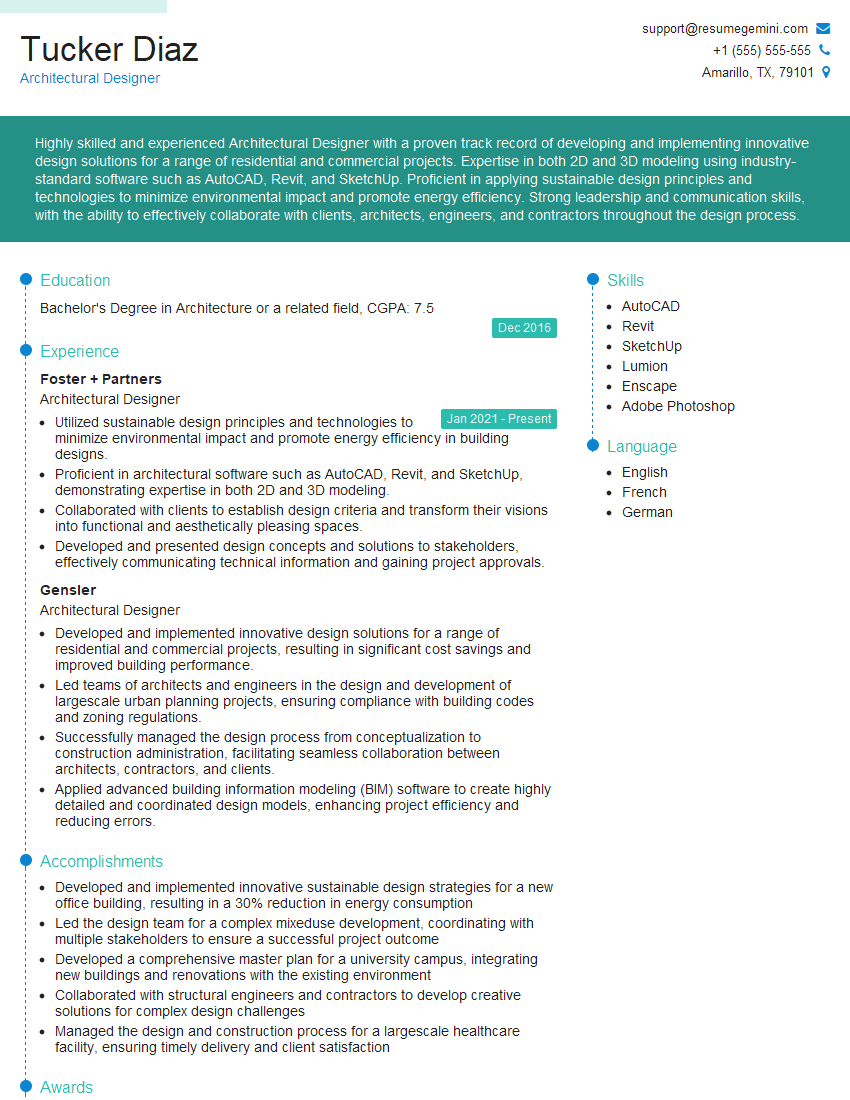
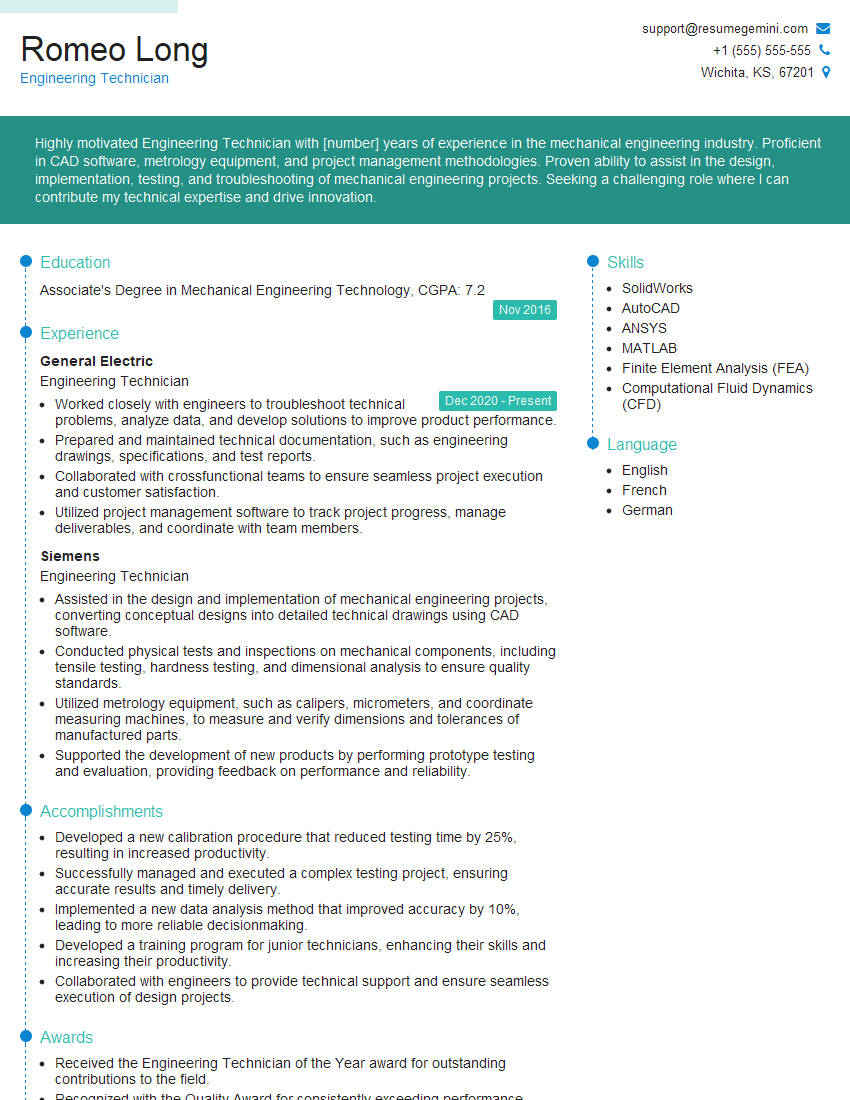
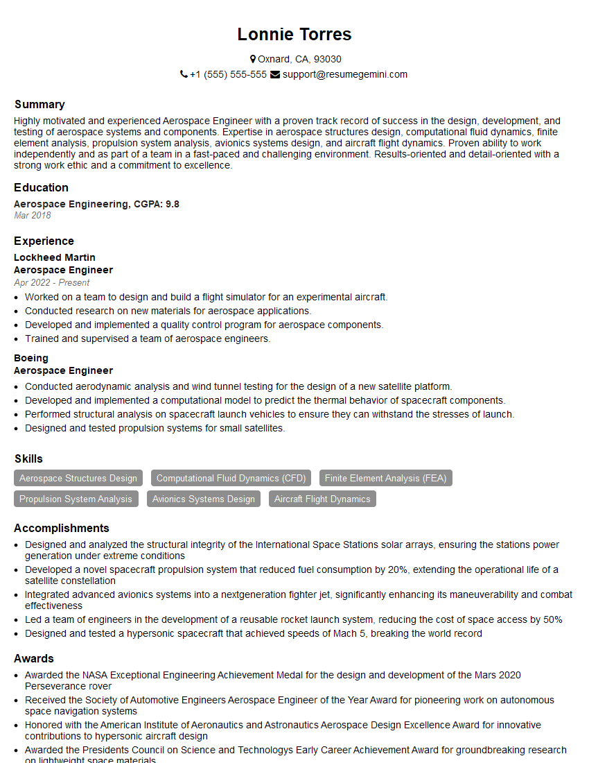
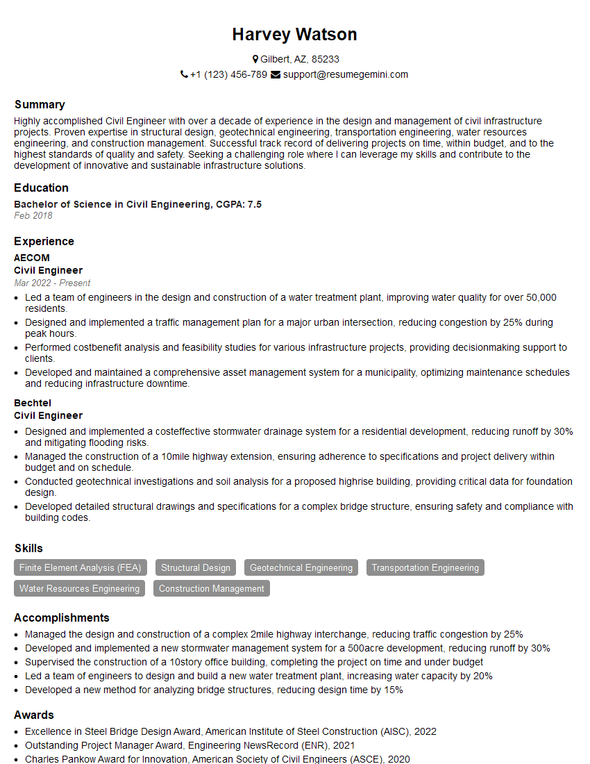
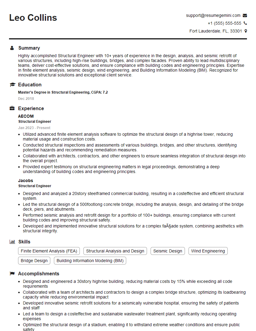
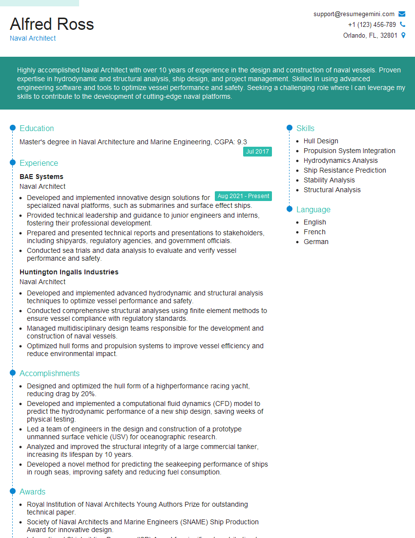
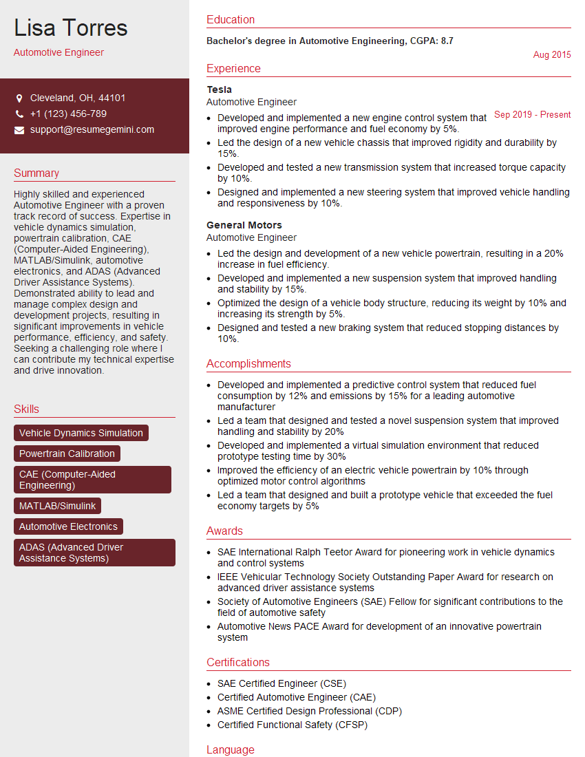
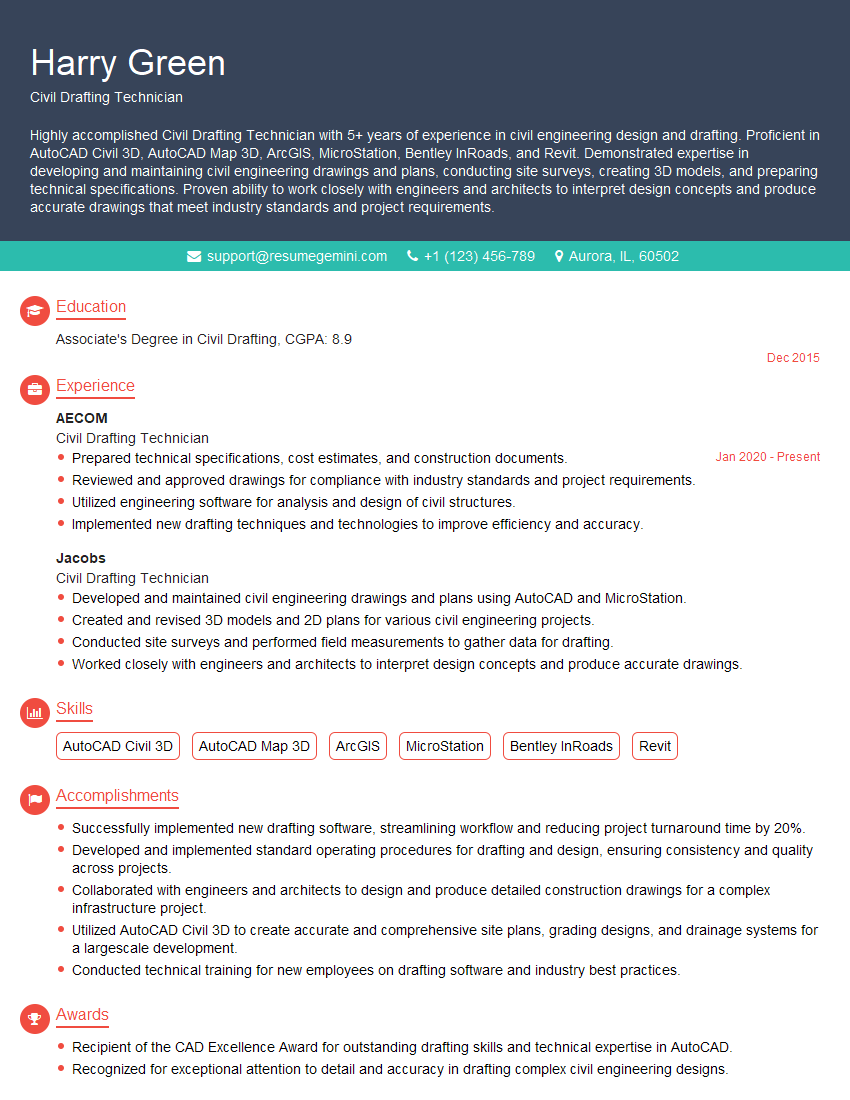
Mastering CAD and Engineering Software is crucial for a successful and rewarding career in engineering. Proficiency in these tools significantly enhances your job prospects and opens doors to exciting opportunities. To maximize your chances of landing your dream role, creating an ATS-friendly resume is paramount. This ensures your qualifications are effectively communicated to recruiters and hiring managers. ResumeGemini is a trusted resource to help you craft a professional and impactful resume that highlights your skills and experience. We offer examples of resumes tailored to the CAD and Engineering Software field to provide you with valuable guidance and inspiration.
Explore more articles
Users Rating of Our Blogs
Share Your Experience
We value your feedback! Please rate our content and share your thoughts (optional).
What Readers Say About Our Blog
Hello,
We found issues with your domain’s email setup that may be sending your messages to spam or blocking them completely. InboxShield Mini shows you how to fix it in minutes — no tech skills required.
Scan your domain now for details: https://inboxshield-mini.com/
— Adam @ InboxShield Mini
Reply STOP to unsubscribe
Hi, are you owner of interviewgemini.com? What if I told you I could help you find extra time in your schedule, reconnect with leads you didn’t even realize you missed, and bring in more “I want to work with you” conversations, without increasing your ad spend or hiring a full-time employee?
All with a flexible, budget-friendly service that could easily pay for itself. Sounds good?
Would it be nice to jump on a quick 10-minute call so I can show you exactly how we make this work?
Best,
Hapei
Marketing Director
Hey, I know you’re the owner of interviewgemini.com. I’ll be quick.
Fundraising for your business is tough and time-consuming. We make it easier by guaranteeing two private investor meetings each month, for six months. No demos, no pitch events – just direct introductions to active investors matched to your startup.
If youR17;re raising, this could help you build real momentum. Want me to send more info?
Hi, I represent an SEO company that specialises in getting you AI citations and higher rankings on Google. I’d like to offer you a 100% free SEO audit for your website. Would you be interested?
Hi, I represent an SEO company that specialises in getting you AI citations and higher rankings on Google. I’d like to offer you a 100% free SEO audit for your website. Would you be interested?
good


