Preparation is the key to success in any interview. In this post, we’ll explore crucial Construction Drawings interview questions and equip you with strategies to craft impactful answers. Whether you’re a beginner or a pro, these tips will elevate your preparation.
Questions Asked in Construction Drawings Interview
Q 1. Explain the difference between a plan, section, and elevation drawing.
Imagine you’re looking at a building. A plan drawing is like looking down from a helicopter – it shows the layout of the building from above, like a map of rooms and their positions. A section drawing is like slicing through the building with a giant knife – it shows the internal structure and how different elements are stacked vertically. Think of it as a cutaway view. Finally, an elevation drawing is like taking a photograph of the building from different sides – it depicts the exterior appearance of the building from each direction (front, rear, sides).
- Plan: Shows floor layouts, room dimensions, door and window locations.
- Section: Shows wall heights, floor-to-ceiling dimensions, and the relationship between different floors and levels.
- Elevation: Shows the exterior facade, detailing windows, doors, roofing, and other exterior features.
For example, a plan might show the location of plumbing fixtures in a bathroom, a section might show how the plumbing pipes run through the walls and floors, and an elevation might show the exterior design of the building’s façade.
Q 2. What are the standard scales used in construction drawings?
Standard scales in construction drawings ensure that the drawings are proportionally representative of the actual building. The scale used depends on the size and complexity of the project. Common scales include:
- 1:100 (1/100): Used for site plans and larger-scale projects, showing a lot of area.
- 1:50 (1/50): Often used for floor plans and smaller site details.
- 1:20 (1/20): Used for detailed drawings of smaller areas, providing more clarity and precision.
- 1:10 (1/10): Useful for very detailed drawings like sections through complex building elements, or large-scale features of a room.
- 1:5 (1/5): For extremely detailed components or sections of significant elements.
- 1:1 (full scale): Used for drawings of specific components or details.
Choosing the appropriate scale is crucial for clear communication and efficient planning. Too small a scale makes details hard to see, while too large a scale might be unwieldy and unnecessary.
Q 3. Describe your experience with different CAD software (e.g., AutoCAD, Revit).
I possess extensive experience with various CAD software packages, most notably AutoCAD and Revit. My AutoCAD skills include proficiency in 2D drafting, creating detailed plans, sections, and elevations, and managing large drawing sets. I’m adept at utilizing various tools within AutoCAD for annotation, dimensioning, and creating schedules.
Furthermore, I am highly proficient in Revit, a BIM software. My experience includes creating and managing 3D models, coordinating various disciplines through linked models, and generating accurate construction documentation directly from the model. I’ve used Revit’s features for clash detection, quantity takeoff, and creating detailed schedules for construction materials. I also have experience using other software such as Civil 3D for site modelling.
I find the transition between 2D and 3D modeling seamless. In projects requiring both, I leverage the strengths of each software, for example, utilizing AutoCAD for precise detailing while relying on Revit for overall project coordination and 3D visualization.
Q 4. How do you ensure drawings are coordinated across different disciplines (e.g., architectural, structural, MEP)?
Coordination across different disciplines is paramount in construction. I employ several strategies to ensure seamless integration:
- Regular Coordination Meetings: Consistent meetings with architects, structural engineers, MEP (Mechanical, Electrical, Plumbing) engineers, and contractors are crucial. These meetings facilitate open communication and early problem identification.
- BIM Software (Revit): Utilizing BIM allows for clash detection, where different disciplines’ models are integrated to highlight conflicts (e.g., a ductwork running through a structural beam). This proactive approach avoids costly on-site modifications.
- Model Coordination Software: Tools like Navisworks allow for visualizing and analyzing the integrated models from all disciplines, providing a comprehensive view of the project.
- Clear Communication Protocols: Establishing clear communication protocols, using standardized drawing formats and naming conventions, reduces ambiguity and promotes efficiency.
- Digital Model Sharing and Version Control: Utilizing cloud-based platforms for secure and collaborative model sharing and version control is crucial to avoid miscommunication and using outdated drawings.
A real-world example: On a recent hospital project, using Revit’s clash detection identified a conflict between the HVAC ductwork and a structural column. This was resolved early in the design phase, saving significant time and cost during construction.
Q 5. How familiar are you with BIM (Building Information Modeling)?
I am very familiar with Building Information Modeling (BIM). My expertise extends to utilizing BIM software (primarily Revit) throughout the entire project lifecycle, from conceptual design to construction and beyond. I understand the power of BIM in improving collaboration, reducing errors, and optimizing building performance. My proficiency includes creating and managing 3D models, generating schedules and quantities, and performing clash detection.
Beyond the technical aspects, I also grasp the importance of BIM in facilitating efficient communication amongst stakeholders and creating a holistic digital representation of the building. My understanding goes beyond just software; I see BIM as a process for improving the entire construction workflow.
Q 6. Explain the importance of layering and organization in CAD drawings.
Layering and organization are critical for managing the complexity of CAD drawings. Think of it like organizing a well-stocked kitchen – everything has its place, and you can easily find what you need. In CAD, layers allow us to separate different elements of the drawing, such as walls, doors, windows, and MEP systems. This makes it easy to:
- Turn elements on/off: Isolate specific aspects of the drawing for clearer visualization.
- Modify elements: Make changes to specific elements without affecting others.
- Print specific elements: Generate different sets of drawings for specific disciplines or contractors.
- Improve collaboration: Each team can work on their assigned layers independently without causing conflicts.
Example: Layer names might include "Walls," "Doors," "Plumbing," "Electrical," etc.
A well-organized drawing with descriptive layer names significantly enhances clarity and collaboration. This also greatly improves the drawing’s ability to be easily managed over the course of a project as changes are implemented.
Q 7. How do you handle revisions and updates to construction drawings?
Handling revisions and updates requires a systematic approach to maintain drawing accuracy and control. I employ the following methods:
- Revision Clouds: Highlighting changes using revision clouds clearly indicates areas that have been modified.
- Revision Schedules: Maintaining a revision schedule documents all changes, including the date, description, and author of the changes. This is crucial for tracking history and accountability.
- Version Control: Using version control systems (e.g., within BIM software or cloud-based platforms) ensures that all stakeholders have access to the latest version. This is critical in a collaborative environment.
- Issue Tracking: Implementing an issue-tracking system to document and address discrepancies or change requests, ensuring that all adjustments are systematically implemented and documented.
- Clear Communication: Prompt and clear communication of revisions to all relevant stakeholders is paramount to avoid confusion and ensure everyone is working from the same up-to-date drawings.
In practice, I’ve found a combination of cloud-based platforms and internal revision control within the BIM software to provide the best level of accessibility and control. This ensures that the correct information is disseminated to all stakeholders and that accountability for changes is always maintained.
Q 8. What are your methods for checking drawings for errors and inconsistencies?
Checking construction drawings for errors and inconsistencies is a crucial part of my workflow, ensuring a smooth and successful project. My method involves a multi-stage approach combining automated checks and meticulous manual reviews.
Automated Checks: I utilize software tools like Autodesk AutoCAD and Revit to identify potential clashes between different disciplines (e.g., architectural, structural, MEP). These tools highlight discrepancies in dimensions, layering, and object placement, allowing for early detection and correction.
Visual Inspection: A thorough visual review is essential. I meticulously examine each drawing, comparing it to related drawings and specifications to identify inconsistencies in notation, dimensions, and details. For example, I’ll check if door swings are properly indicated and if they clash with adjacent walls. I often use a red pen to highlight potential issues directly on the printouts.
Dimensional Checks: I verify dimensions across multiple drawings. A common error is discrepancies between plan, section, and elevation views. I ensure that measurements align correctly and that there are no missing or conflicting information.
Cross-referencing: I cross-reference drawings with the project specifications and schedules to ensure that all elements are accurately depicted and detailed. This involves careful attention to material specifications, finishes, and equipment requirements.
Checklist Approach: A predefined checklist helps maintain consistency and reduces the likelihood of overlooking critical areas. This checklist typically includes items like checking for proper scaling, correct notations, clear labeling, and complete information.
For instance, on a recent project, automated clash detection identified a conflict between a ductwork system and a structural beam. Manual review confirmed the issue, enabling prompt adjustments to the design before construction began, preventing costly delays and rework on site.
Q 9. How do you ensure drawings comply with building codes and regulations?
Compliance with building codes and regulations is paramount. My approach is proactive and involves several key steps:
Early Code Review: I begin by familiarizing myself with the relevant building codes (e.g., IBC, local codes) applicable to the project’s location and type. This establishes a baseline for design decisions.
Code-Specific Software: I utilize software that is integrated with building code requirements, automating some aspects of code compliance checking and flagging potential violations. These tools offer significant time savings and help prevent errors.
Reference Documents: I maintain an up-to-date collection of relevant codes and standards readily available during the design process. This ensures quick access to required information to answer specific questions that arise.
Collaboration with Engineers: I collaborate closely with structural, mechanical, electrical, and plumbing (MEP) engineers, ensuring that all disciplines’ design adhere to the applicable codes. This collaborative approach addresses potential issues early in the design process.
Peer Review: Internal and external peer review processes are crucial, allowing experienced professionals to examine the drawings for code compliance and potential issues I might have overlooked.
Submittal for Review: Before finalization, drawings are submitted to the relevant authorities for review and approval. This ensures that the design officially meets all requirements.
For example, ensuring proper fire-rated separation between different occupancy types is critical. I make sure the designs meet the requirements for appropriate wall assemblies, fire doors, and fire suppression systems, as outlined in the relevant codes.
Q 10. Describe your experience with creating construction details.
Creating construction details is a specialty of mine. It requires a deep understanding of construction practices, material properties, and building codes. My process is iterative and detail-oriented:
Understanding the Context: I start by thoroughly understanding the overall design intent and the specific area requiring detailing. This involves reviewing architectural plans, structural drawings, and other relevant documents to identify potential challenges and opportunities.
Material Selection and Specifications: I consider the intended use and environmental factors when selecting materials. This ensures that the chosen materials are suitable for the intended purpose and comply with building codes.
Detailed Drawings and Sections: I create clear and unambiguous drawings using appropriate scales and annotations. Detailed sections are crucial for showcasing how various building components interact. For example, detailing a connection between a beam and a column needs to illustrate how the load is transferred.
Dimensioning and Notation: Accuracy is paramount. I meticulously dimension all aspects of the detail, using clear and consistent notation. I adhere to industry standards to ensure easy interpretation by contractors.
Coordination with Other Disciplines: I collaborate with other disciplines to ensure that the details integrate seamlessly with other systems. For instance, a detail showing a window installation must consider the interaction with the exterior cladding, the framing, and the interior finish.
Revision and Refinement: I review and refine the details based on feedback from contractors, engineers, and other stakeholders. This iterative process ensures that the final details are both constructible and meet the project requirements.
For example, I once created detailed drawings for a complex curved wall system, involving custom fabrication and installation techniques. The detailed drawings included tolerances, anchoring strategies, and weatherproofing solutions, ensuring that the wall system was successfully constructed without any issues.
Q 11. How do you interpret and use symbols and abbreviations on construction drawings?
Interpreting and using symbols and abbreviations on construction drawings is fundamental. It requires both familiarity with industry standards and attention to detail. I use a combination of techniques:
Familiarization with Standards: I am proficient with commonly used symbols and abbreviations defined in standards like ANSI and ISO. This allows me to quickly decipher the meaning of symbols on drawings.
Reference Documents: Every drawing set includes a legend or key explaining any non-standard symbols or abbreviations. I always refer to this legend to ensure accurate interpretation.
Contextual Understanding: I utilize the surrounding information within the drawings to contextualize symbols and abbreviations. For example, if a symbol is repeated consistently near plumbing fixtures, it’s likely related to plumbing.
Software Assistance: Design software often provides built-in support for interpreting standard symbols and abbreviations. I use these features for efficiency and to avoid misinterpretations.
Cross-checking: When uncertainties arise, I cross-check information across different drawings and specifications to confirm my interpretation.
For instance, understanding the difference between a solid line representing a wall and a dashed line representing a partition is critical for proper construction. Similarly, interpreting pipe diameters and flow directions from symbols on plumbing drawings is crucial for the correct installation of plumbing systems.
Q 12. Explain your process for creating schedules and specifications within the drawing set.
Creating schedules and specifications is an integral part of the drawing set, ensuring consistency and clarity throughout the project. My process is organized and systematic:
Data Gathering: I gather data from various sources, including architectural plans, specifications, and contractor input. This information is crucial for accurate and complete schedules and specifications.
Software Utilization: I use specialized software, often integrated with CAD, to create and manage schedules (e.g., door schedules, window schedules, finish schedules). This automation ensures consistency and reduces manual errors.
Format and Structure: I follow a consistent format and structure for all schedules and specifications, ensuring readability and easy navigation. This includes clear column headings, consistent units, and logical organization.
Cross-referencing: I meticulously cross-reference the schedules and specifications with the drawings to ensure that all information is consistent and accurate. Any discrepancies are promptly addressed.
Revision Control: I maintain a robust revision control system for all schedules and specifications, recording changes and ensuring that everyone has access to the latest versions.
Collaboration: I collaborate with the project team (architects, engineers, contractors) to ensure that the schedules and specifications meet their needs and expectations.
A well-organized door schedule, for example, clearly identifies each door’s location, type, size, finish, and hardware, preventing confusion and ensuring accurate procurement and installation.
Q 13. How do you manage large and complex drawing files?
Managing large and complex drawing files requires a strategic approach to maintain organization and efficiency:
File Organization: I organize files using a logical naming convention, categorized by discipline (architectural, structural, MEP), building section, and revision number. This makes it easy to locate specific files.
Version Control: Employing a robust version control system, like Autodesk Vault or similar cloud-based solutions, is essential for tracking revisions and collaboration among team members. This prevents accidental overwriting and maintains a clear history of design changes.
Data Management Software: Using BIM (Building Information Modeling) software significantly improves management of large files by creating a central database that integrates all aspects of the project. This enhances collaboration and reduces the risk of errors.
File Compression and Archiving: Regularly compressing files and archiving older revisions reduces storage requirements and improves file accessibility.
Cloud Storage: Utilizing cloud storage solutions enhances collaboration and accessibility for the entire project team, regardless of location.
Regular Backups: Implementing a regular backup system, both locally and remotely, is vital to protect against data loss.
On a recent large-scale project, the use of BIM software and a cloud-based collaboration platform allowed multiple teams to work concurrently without version conflicts. This significantly streamlined the design process and improved communication among team members.
Q 14. What are your experience with different drawing formats (e.g., DWG, PDF, IFC)?
My experience encompasses a wide range of drawing formats, each with its own strengths and weaknesses:
DWG (AutoCAD): This is a widely used format, especially for 2D drawings. I am highly proficient in AutoCAD and utilize its tools for precision and detailed drawings. The format allows for extensive customization and layering.
PDF: A universal format excellent for sharing and archiving. While not ideal for editing, PDFs are essential for distributing final drawings to contractors and stakeholders. Their advantage is widespread compatibility.
IFC (Industry Foundation Classes): This is a crucial format for BIM projects, enabling interoperability between different software applications. IFC facilitates data exchange among various disciplines and stakeholders, improving collaboration and data consistency.
For example, I might create detailed drawings in DWG format using AutoCAD, then export them as PDFs for distribution. In a BIM project, I’d leverage IFC for seamless data exchange among the architectural, structural, and MEP teams, allowing for early clash detection and coordination.
Q 15. Describe your experience with using drawing management software.
My experience with drawing management software spans over eight years, encompassing various platforms like Autodesk AutoCAD, Revit, and Bluebeam Revu. I’m proficient in utilizing these tools for creating, editing, revising, and managing construction drawings throughout the entire project lifecycle. This includes tasks such as setting up drawing templates, organizing drawings within a project folder structure, managing revisions using version control, and utilizing markups for collaboration and feedback.
For instance, in a recent large-scale commercial project, we used Revit for BIM (Building Information Modeling) which allowed for real-time collaboration and clash detection between architectural, structural, and MEP disciplines. Bluebeam Revu was crucial for efficient review processes, allowing for seamless markups and streamlined communication with contractors and clients. I am also comfortable with cloud-based solutions for drawing storage and sharing, ensuring efficient access and collaboration within the team and with external stakeholders.
Career Expert Tips:
- Ace those interviews! Prepare effectively by reviewing the Top 50 Most Common Interview Questions on ResumeGemini.
- Navigate your job search with confidence! Explore a wide range of Career Tips on ResumeGemini. Learn about common challenges and recommendations to overcome them.
- Craft the perfect resume! Master the Art of Resume Writing with ResumeGemini’s guide. Showcase your unique qualifications and achievements effectively.
- Don’t miss out on holiday savings! Build your dream resume with ResumeGemini’s ATS optimized templates.
Q 16. How do you handle conflicting information on different drawings?
Conflicting information on drawings is a common challenge. My approach involves a methodical process to identify, document, and resolve these conflicts. The first step is thorough investigation: pinpointing the discrepancies across different drawings (e.g., conflicting dimensions, material specifications, or locations of elements). I carefully analyze each drawing, cross-referencing related documents and specifications to identify the most accurate and up-to-date information.
Once the conflict is understood, I engage in communication with the relevant designers or engineers to determine the correct information. This often involves attending design coordination meetings to discuss and resolve these discrepancies collaboratively. After agreement on the correct information, I create a revision to the affected drawings, clearly documenting the change and its rationale. This revised drawing is then circulated for review and approval before being implemented project-wide. Detailed meeting minutes and revision logs are maintained to ensure complete transparency and accountability.
Q 17. Explain your experience with creating and managing drawing sheets.
Creating and managing drawing sheets is an essential part of my role. I follow a structured approach to ensure clarity, organization, and efficient communication. This begins with creating a comprehensive numbering system, typically following a standardized format (e.g., architectural drawings prefixed with ‘A’, structural with ‘S’, etc.) that maintains consistent numbering throughout the project’s duration.
I carefully organize drawings into sheets, ensuring logical grouping and clear title blocks that include project details, drawing number, revision level, date, and relevant scales. I utilize sheet lists to provide an overview of all drawings within the set, ensuring that the project is comprehensively documented and easily navigated. For large projects, I employ drawing management software to automate some of these processes, managing revisions, and maintaining a consistent filing structure for easy retrieval and access. Imagine it like organizing a vast library – meticulous cataloging is key for easy retrieval and avoids confusion.
Q 18. What is your understanding of shop drawings and their purpose?
Shop drawings are detailed drawings prepared by contractors or fabricators to show how they intend to construct specific elements of a project, based on the original construction drawings. They demonstrate the contractor’s understanding of the design intent and allow for verification before fabrication or installation commences. Their purpose is threefold: to clarify design details, to confirm constructibility, and to identify potential conflicts or issues early in the construction process.
For example, a shop drawing for a custom steel staircase would show detailed dimensions, connection details, material specifications, and the fabrication process. Review of these drawings allows the design team to confirm that the contractor’s interpretation aligns with the design and identify any potential clashes with other systems before fabrication begins, preventing costly delays and rework later in the project.
Q 19. How do you work effectively with other members of the design team?
Effective teamwork is paramount in construction drafting. I foster collaboration through clear communication, active listening, and a proactive approach. I regularly attend design coordination meetings, actively participating in discussions and contributing my expertise. I utilize project management software for efficient communication and file sharing, ensuring that everyone has access to the latest versions of drawings and project information.
I actively seek feedback and value different perspectives, ensuring that all design disciplines are considered and integrated effectively. Building strong working relationships based on mutual respect and trust is key to our success. Open communication and willingness to compromise are crucial in resolving conflicts and ensuring the design integrates seamlessly.
Q 20. Describe a time you had to solve a problem related to construction drawings.
On a recent high-rise project, we encountered a conflict between the architectural and structural drawings regarding the location of a critical structural column. The architectural drawings showed the column encroaching on a planned elevator shaft, a significant issue.
I first identified and documented the conflict using markups in Bluebeam Revu, detailing the discrepancy. Then, I initiated a meeting with the architectural and structural engineers, presenting the conflict clearly and using 3D modeling software to visualize the clash in context. Through collaborative discussion, we determined that a minor adjustment to the column location, while maintaining structural integrity, could resolve the conflict. The necessary revisions were made and approved, and the issue was successfully resolved before construction commenced, avoiding costly rework.
Q 21. What are your strengths and weaknesses when it comes to construction drafting?
My strengths lie in my meticulous attention to detail, my proficiency in various drawing management software, and my ability to communicate complex information effectively. I am a highly organized and efficient worker, able to manage multiple projects simultaneously and meet tight deadlines. I excel at problem-solving and proactive conflict resolution, ensuring that design discrepancies are identified and addressed promptly.
One area I’m continuously working on is further developing my knowledge of advanced BIM functionalities, especially in relation to energy modeling and sustainability analysis. While I understand the basics, I aim to expand my expertise in this crucial area to enhance my contributions to projects aiming for higher levels of sustainability.
Q 22. What software do you prefer and why?
My preferred software is Autodesk AutoCAD, supplemented by Revit for larger, more complex projects. AutoCAD’s precision and flexibility are unparalleled for 2D drafting, particularly when dealing with detailed plans and sections. Its command line interface, while initially requiring a steeper learning curve, allows for incredibly efficient workflow once mastered. Revit, on the other hand, excels in Building Information Modeling (BIM), enabling collaborative design and efficient management of complex projects through its 3D modeling capabilities and integrated database. Choosing between them depends on the project scope; for smaller projects, AutoCAD is usually sufficient, while larger, multi-disciplinary projects benefit significantly from Revit’s BIM functionality. I also possess proficiency in other software like SketchUp for quick visualizations and ArchiCAD, providing me with a wider range of tools to select from based on the project’s specific needs.
Q 23. How do you stay up-to-date with new technologies and software in the field of construction drafting?
Staying current in this rapidly evolving field requires a multi-pronged approach. I actively participate in online forums and communities dedicated to construction drafting and BIM, engaging with fellow professionals and learning about new software updates and techniques. I regularly attend industry conferences and webinars, often offered by software companies themselves or professional organizations. Moreover, I subscribe to industry publications and journals, both print and online, that keep me informed about the latest advancements. Finally, I dedicate time to independent learning, exploring tutorials and online courses to improve my skills in existing and emerging technologies. This combination ensures I maintain a cutting-edge skill set.
Q 24. What is your understanding of the importance of clear and concise annotation on drawings?
Clear and concise annotation is absolutely crucial for successful construction projects. Ambiguous or missing information can lead to costly errors, delays, and even safety hazards. Think of it like a recipe: without clear instructions, the result is unpredictable. Annotations should be unambiguous, using standardized symbols and abbreviations where appropriate, clearly indicating dimensions, materials, specifications, and any relevant details. For example, instead of a vague note like “Install door here,” a proper annotation would specify the door type, size, swing direction, and any fire-rating requirements. Consistent use of layers and text styles in the CAD software further enhances readability. The goal is to provide a readily understandable document for all stakeholders – contractors, engineers, inspectors – ensuring that everyone interprets the drawings the same way.
Q 25. How familiar are you with different construction materials and their representation in drawings?
My understanding of construction materials and their representation in drawings is extensive. I am familiar with various materials’ properties, including their structural capacity, fire resistance, and aesthetic characteristics. This knowledge allows me to accurately represent them in drawings using standardized symbols, sections, and details. For instance, different types of concrete are represented using different hatch patterns, and structural steel is often shown with distinct line weights and symbols indicating its grade and size. I also understand how material selections impact the construction process and can identify potential conflicts or inconsistencies during the design phase. This holistic understanding goes beyond simple visual representation; it involves understanding the material’s performance and implications for the overall structure.
Q 26. Describe your experience with using templates and standards in construction drawing production.
Templates and standards are fundamental to efficient and consistent drawing production. I routinely utilize pre-designed templates that incorporate company-specific standards for title blocks, sheet numbering, and annotation styles. This ensures uniformity across all drawings, making them easier to read and understand. Following industry best practices, like those published by organizations like AIA (American Institute of Architects) or similar national bodies, ensures compliance with relevant regulations and reduces ambiguity. The use of templates and standards saves significant time by providing a pre-formatted framework, allowing me to focus on the specific design details of the project. Maintaining consistency minimizes errors and ensures that the drawings are easily integrated with other project documents.
Q 27. How do you ensure the accuracy of dimensions and annotations on drawings?
Accuracy is paramount in construction drawings. I employ several strategies to ensure dimensional and annotation accuracy. Firstly, I always double-check dimensions using multiple methods, including manual calculations and software-based checks. Secondly, I use constraints and parameters within CAD software to create relationships between dimensions, ensuring that any change in one dimension automatically updates related dimensions, thus preventing inconsistencies. Thirdly, I conduct thorough quality control checks before finalizing the drawings, reviewing them meticulously for any discrepancies or errors. Finally, regular coordination with other disciplines and project stakeholders allows for early detection and correction of any inconsistencies, fostering a collaborative approach to accuracy. This multi-layered approach ensures the production of accurate and reliable construction drawings.
Q 28. What is your experience with creating as-built drawings?
I have significant experience in creating as-built drawings, which are crucial for record-keeping and future maintenance. This involves meticulously documenting the final construction details, often updating the original drawings to reflect any changes or deviations made during construction. This typically involves fieldwork, measuring and photographing completed structures, to accurately reflect the final state. I use both digital and manual methods, incorporating field measurements and photographs into the updated drawings. Software tools play a vital role in this process, enabling efficient comparison between the original design and the as-built conditions. The accurate as-built drawings are essential for future renovations, repairs, and facility management, serving as an invaluable historical record of the project.
Key Topics to Learn for Construction Drawings Interview
- Blueprint Reading Fundamentals: Understanding scales, symbols, and annotations; interpreting plan, elevation, section, and detail drawings.
- Practical Application: Identifying different building components (foundations, framing, MEP systems) from drawings and visualizing their assembly.
- Architectural Drawings: Analyzing floor plans, wall sections, and details to understand spatial relationships and construction methods.
- Structural Drawings: Interpreting structural framing plans, foundation details, and reinforcement drawings; understanding load paths and structural elements.
- MEP Drawings (Mechanical, Electrical, Plumbing): Identifying and understanding the location and routing of HVAC systems, electrical conduits, and plumbing fixtures.
- Construction Sequencing and Coordination: Understanding the logical order of construction phases and identifying potential conflicts between different trades.
- Problem-Solving: Analyzing drawings to identify potential errors or omissions; proposing solutions and suggesting improvements.
- Drawing Revisions and Updates: Understanding the process of incorporating revisions and updates into existing drawings.
- Building Codes and Regulations: Understanding how drawings reflect adherence to building codes and relevant regulations.
- Software Proficiency (if applicable): Demonstrating familiarity with relevant software like AutoCAD, Revit, or Bluebeam.
Next Steps
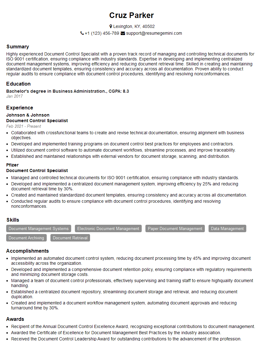
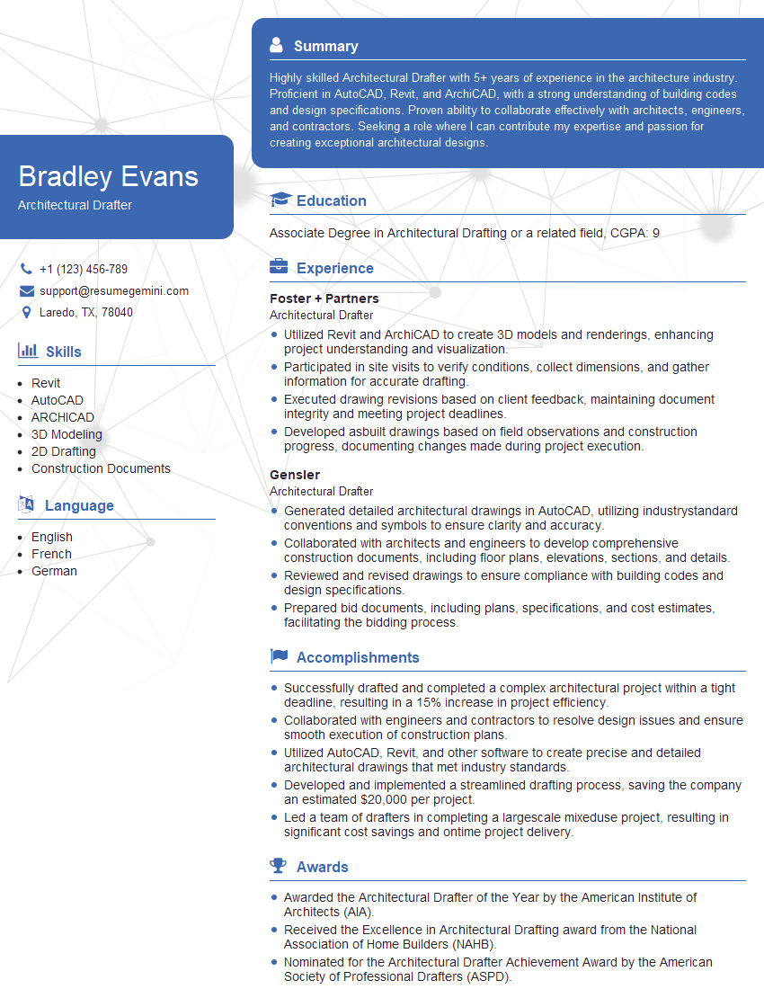
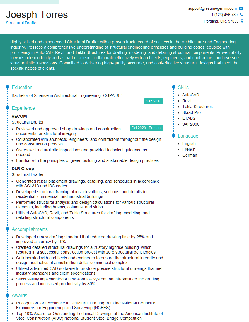
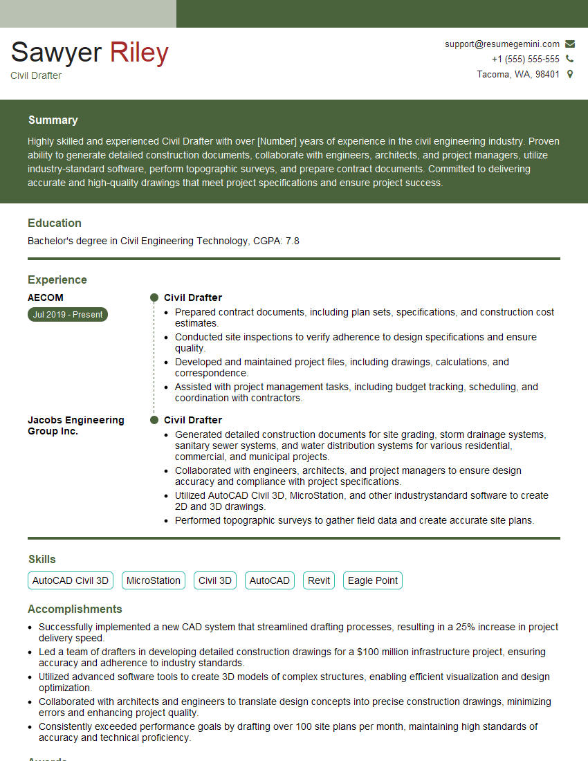
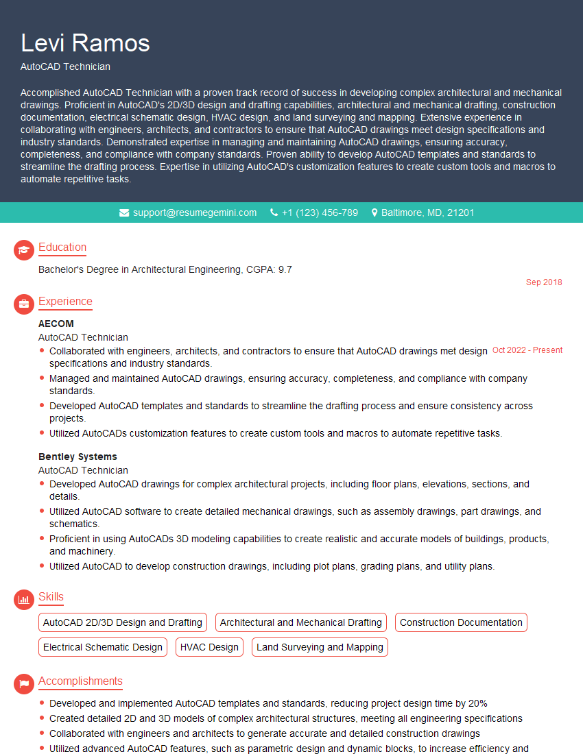
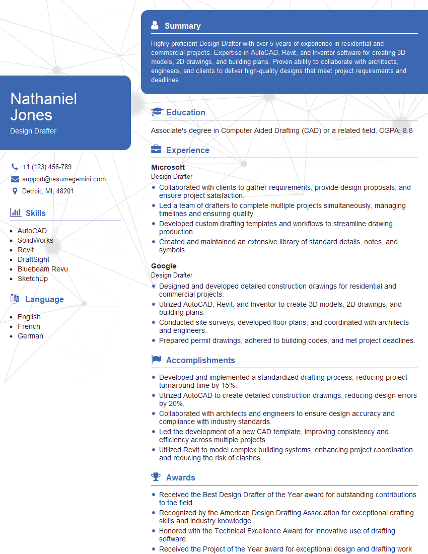
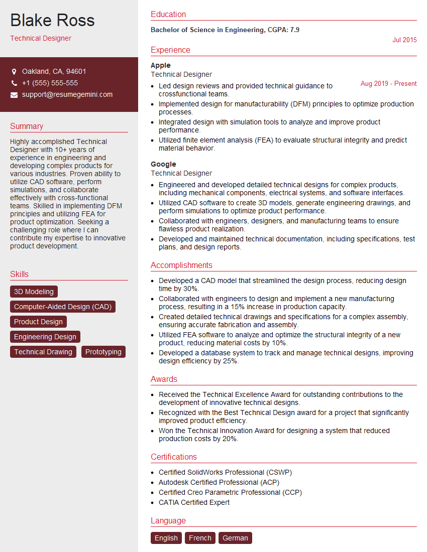
Mastering construction drawings is crucial for career advancement in the construction industry. A strong understanding of these drawings allows you to contribute effectively to project planning, execution, and management. To significantly boost your job prospects, creating an ATS-friendly resume is essential. This ensures your application gets noticed by recruiters and hiring managers. We highly recommend using ResumeGemini to build a professional, impactful resume that highlights your skills and experience. ResumeGemini provides examples of resumes tailored to Construction Drawings expertise, giving you a head start in crafting a compelling application.
Explore more articles
Users Rating of Our Blogs
Share Your Experience
We value your feedback! Please rate our content and share your thoughts (optional).
What Readers Say About Our Blog
Hello,
We found issues with your domain’s email setup that may be sending your messages to spam or blocking them completely. InboxShield Mini shows you how to fix it in minutes — no tech skills required.
Scan your domain now for details: https://inboxshield-mini.com/
— Adam @ InboxShield Mini
Reply STOP to unsubscribe
Hi, are you owner of interviewgemini.com? What if I told you I could help you find extra time in your schedule, reconnect with leads you didn’t even realize you missed, and bring in more “I want to work with you” conversations, without increasing your ad spend or hiring a full-time employee?
All with a flexible, budget-friendly service that could easily pay for itself. Sounds good?
Would it be nice to jump on a quick 10-minute call so I can show you exactly how we make this work?
Best,
Hapei
Marketing Director
Hey, I know you’re the owner of interviewgemini.com. I’ll be quick.
Fundraising for your business is tough and time-consuming. We make it easier by guaranteeing two private investor meetings each month, for six months. No demos, no pitch events – just direct introductions to active investors matched to your startup.
If youR17;re raising, this could help you build real momentum. Want me to send more info?
Hi, I represent an SEO company that specialises in getting you AI citations and higher rankings on Google. I’d like to offer you a 100% free SEO audit for your website. Would you be interested?
Hi, I represent an SEO company that specialises in getting you AI citations and higher rankings on Google. I’d like to offer you a 100% free SEO audit for your website. Would you be interested?
good
