The right preparation can turn an interview into an opportunity to showcase your expertise. This guide to Basic knowledge of electrical theory interview questions is your ultimate resource, providing key insights and tips to help you ace your responses and stand out as a top candidate.
Questions Asked in Basic knowledge of electrical theory Interview
Q 1. What is Ohm’s Law and how is it applied?
Ohm’s Law is a fundamental principle in electrical circuits that describes the relationship between voltage, current, and resistance. It states that the current flowing through a conductor is directly proportional to the voltage across it and inversely proportional to its resistance. This relationship is expressed mathematically as:
V = IR
where:
Vrepresents voltage (measured in volts)Irepresents current (measured in amperes)Rrepresents resistance (measured in ohms)
Application: Ohm’s Law is crucial for circuit analysis and design. For example, if you know the voltage applied to a resistor and its resistance, you can calculate the current flowing through it. Similarly, if you know the current and resistance, you can determine the voltage. This law is applied extensively in everything from simple light bulb circuits to complex integrated circuits.
Example: A 12V battery is connected to a 4-ohm resistor. Using Ohm’s Law (I = V/R), the current flowing through the resistor is I = 12V / 4Ω = 3A.
Q 2. Explain the difference between AC and DC current.
The key difference between AC (Alternating Current) and DC (Direct Current) lies in the direction of electron flow. In DC circuits, electrons flow consistently in one direction, like water flowing downhill in a stream. In AC circuits, the electron flow direction periodically reverses, similar to a water wave moving back and forth.
DC Current: Provided by batteries or power supplies. The voltage and current remain constant over time. Simple and easier to understand, but less efficient for long-distance power transmission.
AC Current: Used for most household and industrial power distribution. The voltage and current alternate direction periodically. More efficient for long-distance power transmission because voltage can be easily stepped up and down using transformers. Most commonly found in household electrical outlets.
Q 3. What are Kirchhoff’s laws?
Kirchhoff’s laws are two fundamental laws used to analyze complex electrical circuits. They provide a systematic approach to solving circuit problems.
Kirchhoff’s Current Law (KCL): This law states that the sum of currents entering a junction (or node) in a circuit is equal to the sum of currents leaving that junction. Think of it like a water pipe junction—the total water flow entering must equal the total water flow leaving. This reflects the conservation of charge.
Kirchhoff’s Voltage Law (KVL): This law states that the sum of the voltage drops around any closed loop in a circuit is equal to zero. Imagine walking around a closed circuit; the total rise and fall in voltage must add up to zero when you return to your starting point. This reflects the conservation of energy.
Application: These laws are vital for analyzing circuits with multiple branches and loops, allowing us to determine unknown voltages and currents.
Q 4. Describe the function of a resistor, capacitor, and inductor.
Resistors, capacitors, and inductors are fundamental passive components in electrical circuits, each with a unique function:
- Resistor: A resistor opposes the flow of current. It’s like a narrow pipe restricting water flow. Its resistance is measured in ohms (Ω). Resistors are used to limit current, divide voltage, and provide bias in circuits.
- Capacitor: A capacitor stores electrical energy in an electric field. Think of it as a water reservoir that stores water. It consists of two conductive plates separated by an insulator. Capacitors are used for energy storage, filtering, timing circuits, and coupling AC signals.
- Inductor: An inductor stores electrical energy in a magnetic field. Imagine a spring storing mechanical energy. It’s a coil of wire that creates a magnetic field when current flows through it. Inductors are used in filters, energy storage, and switching power supplies.
Q 5. What is the purpose of a fuse or circuit breaker?
Fuses and circuit breakers are safety devices designed to protect circuits from overcurrent, which can cause overheating, fire, and damage to equipment. They act as a failsafe mechanism.
Fuse: A fuse contains a thin wire that melts and breaks the circuit if the current exceeds a specified limit. Once a fuse blows, it needs to be replaced. Think of it as a one-time safety valve.
Circuit Breaker: A circuit breaker is a more sophisticated device that uses an electromagnet or bimetallic strip to interrupt the circuit when the current is too high. It can be reset after tripping, making it reusable.
Application: Both fuses and circuit breakers are essential for preventing electrical hazards in homes, vehicles, and industrial settings.
Q 6. Explain series and parallel circuits.
Series and parallel are two fundamental ways of connecting components in an electrical circuit:
Series Circuit: In a series circuit, components are connected end-to-end, forming a single path for current flow. The current is the same through all components, but the voltage is divided across them. Imagine a single-lane road where all cars must travel through in sequence.
Parallel Circuit: In a parallel circuit, components are connected across each other, providing multiple paths for current flow. The voltage is the same across all components, but the current is divided among them. Think of multiple lanes on a highway where cars can take different paths.
Q 7. How do you calculate total resistance in a series circuit?
In a series circuit, the total resistance (RT) is simply the sum of the individual resistances (R1, R2, R3,…).
RT = R1 + R2 + R3 + ...
Example: If you have three resistors with values of 10Ω, 20Ω, and 30Ω connected in series, the total resistance is RT = 10Ω + 20Ω + 30Ω = 60Ω.
Q 8. How do you calculate total resistance in a parallel circuit?
Calculating the total resistance in a parallel circuit is different from a series circuit. In a series circuit, you simply add the resistances together. However, in a parallel circuit, the total resistance is always less than the smallest individual resistance. This is because the current has multiple paths to flow through. Think of it like adding more lanes to a highway – it allows more traffic (current) to flow.
The formula for calculating total resistance (RT) in a parallel circuit with two or more resistors is:
1/RT = 1/R1 + 1/R2 + 1/R3 + ...Where R1, R2, R3, etc., are the individual resistances. After calculating the sum of the reciprocals, remember to invert the result to find RT.
Example: Let’s say you have three resistors in parallel: R1 = 10 ohms, R2 = 20 ohms, and R3 = 30 ohms.
1/RT = 1/10 + 1/20 + 1/30 = 0.1 + 0.05 + 0.0333 = 0.1833Therefore:
RT = 1/0.1833 ≈ 5.45 ohmsAs you can see, the total resistance (5.45 ohms) is less than the smallest individual resistance (10 ohms).
Q 9. What is electrical power, and how is it calculated?
Electrical power represents the rate at which electrical energy is consumed or transferred in a circuit. Think of it like the speed at which water flows through a pipe – a higher flow rate means more water is moved in a given time. Similarly, higher power means more energy is used or transferred per unit of time.
Power (P) can be calculated using several formulas, depending on what information you have:
P = V * I(Power equals voltage multiplied by current)P = I² * R(Power equals current squared multiplied by resistance)P = V² / R(Power equals voltage squared divided by resistance)
Where:
- P is power (measured in Watts)
- V is voltage (measured in Volts)
- I is current (measured in Amperes)
- R is resistance (measured in Ohms)
Example: A light bulb with a resistance of 100 ohms is connected to a 120V power supply. To find the power consumed:
P = V² / R = (120V)² / 100 ohms = 144 WattsThis means the light bulb consumes 144 Joules of energy per second.
Q 10. What are the units for voltage, current, and resistance?
The fundamental units in electrical theory are:
- Voltage (V): Measured in Volts (V). Voltage represents the electrical potential difference between two points in a circuit. Think of it as the electrical ‘pressure’ that pushes the current through the circuit. A higher voltage means a stronger push.
- Current (I): Measured in Amperes (A) or Amps. Current represents the flow of electrical charge. It’s the rate at which electrons move through a conductor. More amps mean more electrons flowing per second.
- Resistance (R): Measured in Ohms (Ω). Resistance is the opposition to the flow of current. Think of it as friction in a pipe – it restricts the flow of water (current). Higher resistance means less current flows for a given voltage.
Q 11. Explain the concept of impedance.
Impedance is a more general term than resistance. While resistance opposes the flow of direct current (DC), impedance opposes the flow of alternating current (AC). The key difference lies in the fact that AC current constantly changes direction, introducing effects not seen with DC. These effects, primarily capacitance and inductance, contribute to impedance.
Resistance is a purely resistive component, meaning it only dissipates energy as heat. Capacitance and inductance, on the other hand, store energy in electric and magnetic fields, respectively, and release it back into the circuit. This energy storage and release affect the current flow in a complex way.
Impedance (Z) is measured in ohms and is a complex number, meaning it has both a magnitude and a phase angle. The magnitude represents the overall opposition to current flow, while the phase angle describes the time delay between voltage and current.
In simple AC circuits, impedance can be calculated using similar formulas to resistance, but considering the effects of capacitance (XC) and inductance (XL):
Z = √(R² + (XL - XC)²)Q 12. What is a transformer and how does it work?
A transformer is a passive electrical device that transfers electrical energy between two or more circuits through electromagnetic induction. It’s primarily used to change the voltage level of an AC power supply. This is crucial for efficient long-distance power transmission and for adapting voltages to suit different appliances.
Transformers consist of two or more coils of wire (windings) wound around a ferromagnetic core. The primary winding is connected to the input voltage, and the secondary winding provides the output voltage. When AC current flows through the primary winding, it creates a fluctuating magnetic field in the core. This field induces a voltage in the secondary winding, according to Faraday’s law of induction. The ratio of the number of turns in the primary and secondary windings determines the voltage transformation ratio.
If the secondary winding has more turns than the primary, the voltage is stepped up (increased). If it has fewer turns, the voltage is stepped down (decreased). Power remains relatively constant (ignoring losses), so a step-up in voltage leads to a step-down in current, and vice-versa.
Q 13. Describe different types of wiring (e.g., single-phase, three-phase).
Different types of wiring systems cater to various power requirements and applications. The choice depends on factors like voltage, current capacity, and the number of phases.
- Single-phase AC: This is the most common type used in homes and small businesses. It utilizes two wires – a ‘hot’ wire carrying the AC voltage and a neutral wire returning the current to the source. Typically provides 120V or 240V.
- Three-phase AC: This system uses three hot wires and a neutral wire (in some configurations). It provides a more efficient way to deliver higher power, commonly used in industrial settings and larger buildings. Three-phase systems offer advantages in terms of power distribution and motor operation.
Other variations exist, such as two-phase systems (less common nowadays) and DC wiring systems (used in specialized applications like electric vehicles and some industrial controls).
The choice of wiring also depends on the voltage and amperage involved, which dictate the wire gauge and insulation needed for safety and to prevent overheating.
Q 14. What are the safety precautions when working with electricity?
Working with electricity can be extremely dangerous. Always prioritize safety and follow these precautions:
- Never work on live circuits: Always de-energize the circuit before working on it. Use appropriate lockout/tagout procedures to prevent accidental energization.
- Use appropriate personal protective equipment (PPE): This includes insulated gloves, safety glasses, and appropriate footwear.
- Understand the circuit: Before touching any wires or components, fully understand the circuit’s configuration and voltage levels. Use a multimeter to verify that the circuit is de-energized.
- Work in a well-lit area: Good lighting improves visibility and reduces the risk of accidents.
- Avoid working alone: Have a colleague present who can provide assistance in case of an emergency.
- Know how to respond to electrical shocks: Understand CPR and first aid procedures for electrical injuries.
- Follow all relevant safety regulations and codes: Consult local and national electrical codes for specific requirements.
If you are not qualified or unsure about anything, always consult a qualified electrician.
Q 15. Explain grounding and its importance.
Grounding, or earthing, is the process of connecting a circuit or electrical equipment to the earth, providing a path for excess electrical current to flow safely into the ground. Think of it as a safety valve for electricity.
Its importance stems from its role in preventing electrical shocks and equipment damage. If a fault occurs and a live wire comes into contact with the metal casing of an appliance, grounding prevents the casing from becoming energized. The current will flow through the ground wire instead of shocking anyone who touches it. This is crucial for safety in homes, offices and industrial settings. Without grounding, even minor faults could lead to severe electric shocks or fires.
- Safety: Prevents electric shocks by providing a low-resistance path for fault currents.
- Equipment Protection: Protects equipment from voltage surges and other electrical anomalies.
- Noise Reduction: Can help reduce electrical noise in sensitive circuits.
Career Expert Tips:
- Ace those interviews! Prepare effectively by reviewing the Top 50 Most Common Interview Questions on ResumeGemini.
- Navigate your job search with confidence! Explore a wide range of Career Tips on ResumeGemini. Learn about common challenges and recommendations to overcome them.
- Craft the perfect resume! Master the Art of Resume Writing with ResumeGemini’s guide. Showcase your unique qualifications and achievements effectively.
- Don’t miss out on holiday savings! Build your dream resume with ResumeGemini’s ATS optimized templates.
Q 16. What is a schematic diagram?
A schematic diagram is a simplified visual representation of an electrical circuit. It uses standardized symbols to represent components like resistors, capacitors, transistors, and integrated circuits, along with the connections between them. Imagine it’s like a blueprint for an electrical system.
Schematic diagrams are crucial for understanding the functionality of a circuit, troubleshooting problems, and designing new circuits. They provide a clear and concise representation of the circuit’s topology and component values. They’re much simpler than a physical representation of the circuit and allow for better understanding of the circuit’s behavior. For example, instead of seeing a jumbled pile of wires and components, you see a clear, organized path of electricity.
Consider the simplicity of a light switch. A schematic would show the power source, the switch, and the light bulb connected in a series, making it obvious how the switch controls the light’s power.
Q 17. What is the difference between voltage and potential difference?
While often used interchangeably, voltage and potential difference are essentially the same thing: the driving force that pushes electric current through a circuit. However, the term ‘potential difference’ is more precise and often preferred in technical contexts.
Voltage is the electrical potential energy difference between two points in a circuit. It’s measured in volts (V). Think of it as the pressure pushing water through a pipe. A higher voltage means a greater push.
Potential difference simply clarifies that this ‘voltage’ is a difference in potential between two specific points. It highlights that the voltage is relative to a reference point. For example, the potential difference between the positive and negative terminals of a battery is the battery’s voltage.
Q 18. What is a diode and how does it work?
A diode is a semiconductor device that allows current to flow in only one direction. It’s like a one-way valve for electricity.
It works based on the properties of a p-n junction (a junction between p-type and n-type semiconductor materials). When forward biased (positive voltage applied to the p-side and negative to the n-side), the p-n junction allows current to flow relatively easily. When reverse biased (opposite polarity), the junction acts as an insulator, blocking current flow. This unidirectional property is vital in many electronic applications.
Think of a diode in a circuit preventing current from flowing backward, protecting other components or rectifying alternating current (AC) to direct current (DC).
Q 19. What is a transistor and its basic function?
A transistor is a semiconductor device used to amplify or switch electronic signals and electrical power. It’s a fundamental building block of modern electronics.
Transistors work by controlling a larger current flow with a smaller controlling current. Think of it as an electronic switch controlled by a smaller signal. There are various types like Bipolar Junction Transistors (BJTs) and Field Effect Transistors (FETs), each having its own characteristics and applications. They are found in almost every electronic device. Without transistors, we wouldn’t have computers, smartphones, or many other modern conveniences.
Q 20. Explain the concept of short circuit and open circuit.
Short Circuit: A short circuit occurs when an unintended path of very low resistance is created between two points of different potential in a circuit. This allows a large current to flow, often exceeding the circuit’s design limits, potentially causing damage or a fire. Imagine a direct, short connection between the positive and negative terminals of a battery – a massive current would flow.
Open Circuit: An open circuit is a break in the conductive path of a circuit. This interrupts the flow of current. Think of a broken wire in a lamp – the light won’t turn on because the circuit is incomplete. While short circuits are dangerous due to excessive current, open circuits simply stop current flow.
Q 21. What is a multimeter and how is it used?
A multimeter is a handheld electronic measuring instrument used to measure various electrical properties such as voltage, current, and resistance. It’s an essential tool for electricians and electronics hobbyists alike.
To use a multimeter, you first select the appropriate function (voltage, current, resistance) and range using the dials or buttons. Then, connect the probes to the circuit according to the instructions. The display will show the measured value. For example, to measure voltage, you connect the probes across the two points where you want to measure the voltage. For current measurement, you need to connect it in series with the circuit. Always follow safety precautions and ensure the multimeter is set to the correct range to avoid damage to the meter or the circuit.
Q 22. How do you read a wiring diagram?
Reading a wiring diagram is like following a map for electricity. It shows you the path electricity takes through a circuit. You’ll see symbols representing different components – wires, switches, lights, motors, etc. – and lines connecting them, indicating how they’re wired together.
Start by identifying the power source (usually a battery or power supply, represented by a symbol). Then, trace the flow of current from the power source, following the lines. Pay close attention to the symbols – understanding what each component does is crucial. For instance, a switch symbol will indicate a point where the circuit can be opened or closed, controlling the flow of current. Many diagrams use color-coding for different wires (e.g., hot, neutral, ground), which you should also pay attention to.
For example, imagine a simple circuit diagram for a light switch. You’d see the power source, the switch, the light bulb, and lines connecting them. Following the lines shows how turning the switch on and off completes or breaks the circuit, controlling the light. More complex diagrams might show multiple circuits and components, requiring more careful tracing and understanding of the symbols involved.
Q 23. What is the difference between conductors and insulators?
Conductors and insulators are two fundamental types of materials in electrical systems, distinguished by their ability to conduct electric current.
- Conductors: These materials readily allow electric current to flow through them. This is because they have loosely bound electrons in their atomic structure, which can move freely when an electric field is applied. Examples include copper, aluminum, silver, and gold – materials commonly used in electrical wiring. The ease with which a conductor allows current to flow is measured by its conductivity or, conversely, its resistivity.
- Insulators: These materials strongly resist the flow of electric current. Their electrons are tightly bound to their atoms, making it difficult for current to pass through. Examples include rubber, plastic, glass, and air. Insulators are used to prevent short circuits and protect people from electric shock. They are essential for safely containing and directing the flow of electricity.
Think of it like water flowing through pipes. Conductors are like wide-open pipes, allowing water (electricity) to flow easily. Insulators are like completely sealed pipes, preventing the water from flowing.
Q 24. Explain the concept of capacitance.
Capacitance is the ability of a system to store electrical energy in an electric field. It’s essentially the capacity to hold charge. The simplest form of a capacitor consists of two conductive plates separated by an insulating material called a dielectric.
When a voltage is applied across the plates, electrons accumulate on one plate, creating a negative charge, while electrons are drawn away from the other plate, leaving a positive charge. This charge separation creates an electric field within the dielectric. The amount of charge that can be stored is directly proportional to the voltage applied and the capacitance of the capacitor. The capacitance itself depends on the geometry of the capacitor (area of the plates and the distance between them) and the properties of the dielectric material.
The unit of capacitance is the farad (F), but practical capacitors are usually measured in microfarads (µF) or picofarads (pF). Capacitors are used in a wide variety of applications, including filtering noise in power supplies, timing circuits, energy storage in some electronic devices, and signal coupling/decoupling in audio circuits.
Q 25. Explain the concept of inductance.
Inductance is the property of an electrical conductor by which a change in the current flowing through it induces a voltage in itself and possibly in nearby conductors. This phenomenon is due to the magnetic field created by the current.
When current flows through a conductor, it generates a magnetic field around it. If the current changes, the magnetic field changes as well. This changing magnetic field induces a voltage in the conductor itself that opposes the change in current. This self-induced voltage is proportional to the rate of change of the current and the inductance of the conductor. The higher the inductance, the greater the opposition to the change in current.
Inductors are components specifically designed to exhibit inductance. They usually consist of a coil of wire, often wound around a core material (e.g., iron or ferrite) to enhance the magnetic field. Inductors are used in various applications, including filtering high-frequency noise, energy storage in some power supplies, and inductors are essential elements in resonant circuits used in radio and other frequency-based applications.
Q 26. What is a relay and how does it work?
A relay is an electrically operated switch. It uses a small electrical current to control a much larger current. Imagine a small switch controlling a powerful motor or a large number of lights – this is exactly what a relay does.
It consists of an electromagnet, a set of contacts, and a spring mechanism. When a small control current is applied to the electromagnet, it becomes energized and attracts a movable armature. This armature moves, closing the contacts, completing a circuit that may carry the large current. When the control current is removed, the spring returns the armature to its original position, opening the contacts and breaking the circuit. Relays are used in numerous applications, including automotive systems, industrial control systems, and household appliances, allowing for safe and efficient control of high-power circuits using lower-power signals.
Q 27. Describe different types of batteries and their applications.
Batteries are electrochemical devices that convert chemical energy into electrical energy. Many different types exist, each with its own characteristics and applications:
- Primary (disposable) batteries: These batteries are single-use, meaning they cannot be recharged. Examples include alkaline batteries (common in household devices) and zinc-carbon batteries (older technology). Their advantages are low cost and readily available; however, they are not environmentally friendly and have relatively short lifespans.
- Secondary (rechargeable) batteries: These batteries can be recharged multiple times. Examples include lead-acid batteries (used in cars), nickel-cadmium (NiCd) batteries (older technology with environmental concerns), nickel-metal hydride (NiMH) batteries (better than NiCd), and lithium-ion (Li-ion) batteries (used in laptops, smartphones, and electric vehicles). Li-ion batteries offer high energy density and long lifespans, making them popular for portable electronics and electric vehicles.
The choice of battery depends on the application’s power requirements, lifespan needs, cost considerations, and environmental impact. For instance, lead-acid batteries’ high current capacity makes them suitable for car starters, while lithium-ion batteries’ high energy density is ideal for portable devices.
Q 28. What is a motor and how does it work?
An electric motor is a device that converts electrical energy into mechanical energy. Essentially, it uses electricity to create motion.
The most common type is the DC motor. It works by using a magnetic field to create a force on a current-carrying conductor. A simple DC motor has a rotor (the rotating part) with a coil of wire, and a stator (the stationary part) containing magnets. When current flows through the coil, it creates a magnetic field that interacts with the stator’s magnetic field. This interaction produces a force on the coil, causing the rotor to rotate. A commutator and brushes are often used to periodically reverse the direction of current in the coil, ensuring continuous rotation.
AC motors use alternating current to create a rotating magnetic field which then induces current in the rotor, causing it to rotate. These come in many forms, including induction motors and synchronous motors, and are commonly found in industrial applications, appliances, and power tools.
Key Topics to Learn for Basic Electrical Theory Interviews
- Ohm’s Law and Circuit Analysis: Understand the relationship between voltage, current, and resistance. Practice calculating circuit parameters in simple series and parallel circuits. This is fundamental to almost all electrical applications.
- Kirchhoff’s Laws: Learn how to apply Kirchhoff’s current and voltage laws to analyze more complex circuits. This allows for solving circuits with multiple voltage sources and branches.
- Power and Energy Calculations: Be comfortable calculating electrical power and energy consumption. Understand the difference between active and reactive power (for AC circuits). This is crucial for efficiency and cost analysis.
- DC and AC Circuits: Differentiate between direct current (DC) and alternating current (AC) circuits. Understand the characteristics of sinusoidal waveforms (frequency, amplitude, phase). This forms the basis of many electrical systems.
- Basic Components: Familiarize yourself with the function and characteristics of common electrical components like resistors, capacitors, inductors, diodes, and transistors. Knowing their basic operation is essential for understanding circuit behavior.
- Electrical Safety: Understand basic electrical safety precautions and regulations. This demonstrates responsibility and awareness of potential hazards in electrical work.
- Problem-solving techniques: Practice applying your knowledge to solve simple circuit problems. Develop a systematic approach to troubleshooting and diagnosis.
Next Steps
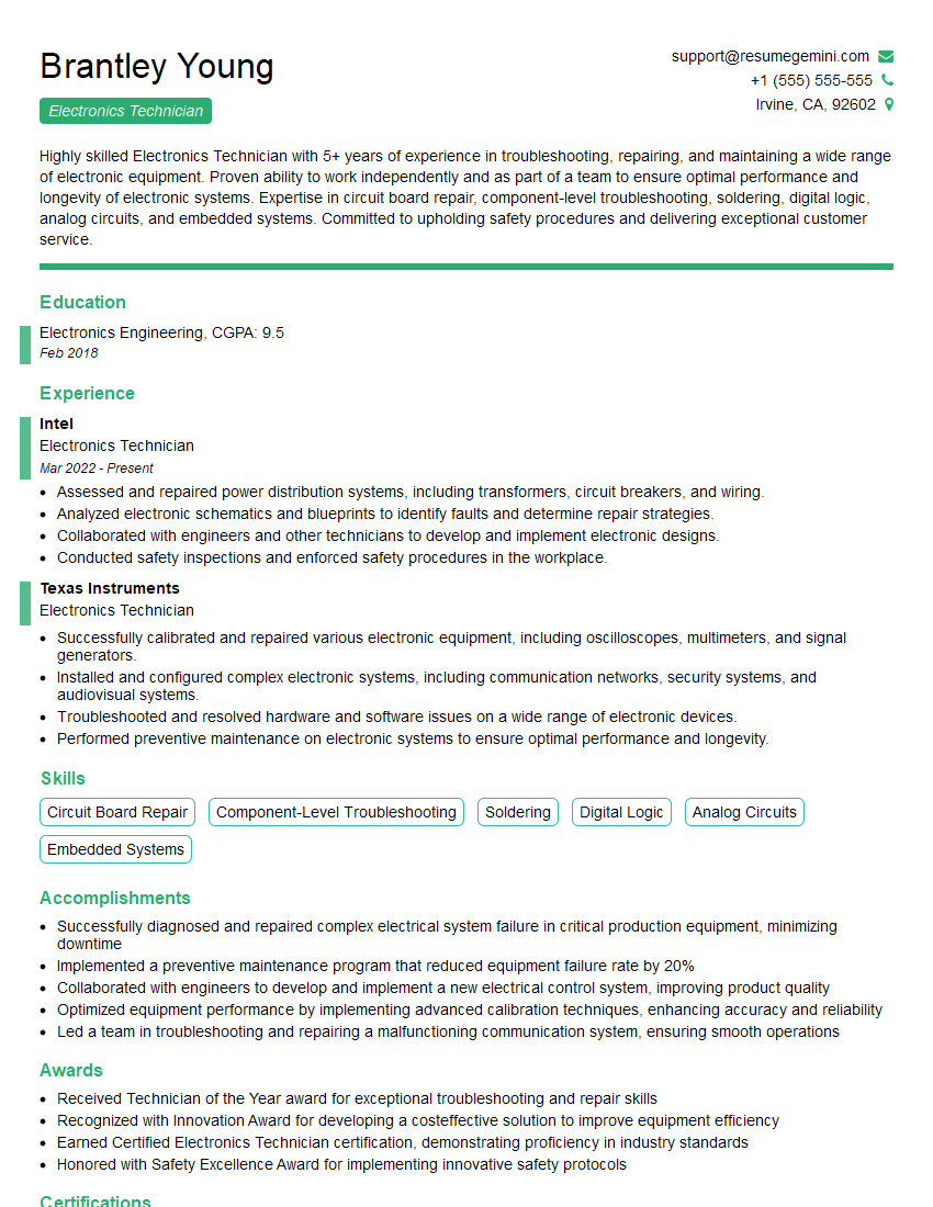
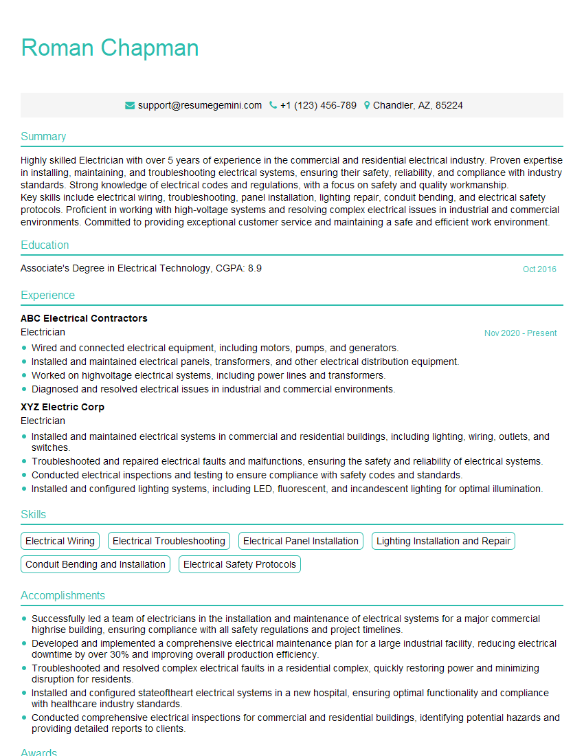
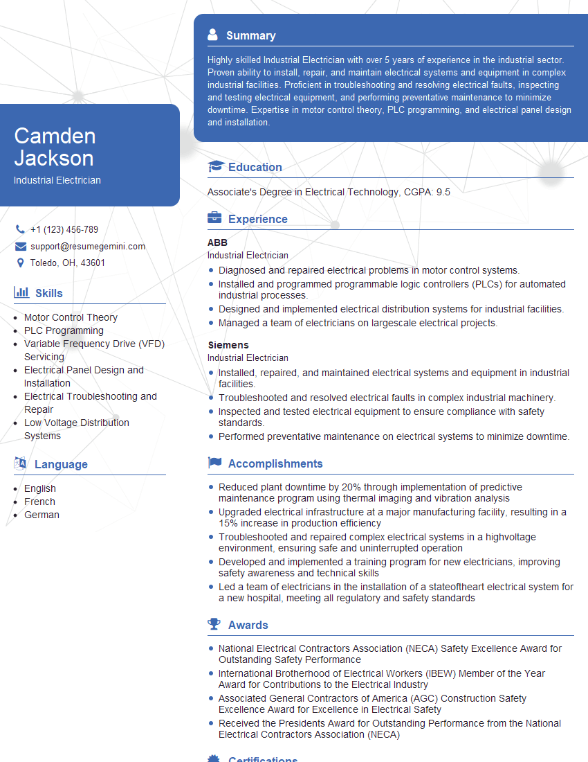
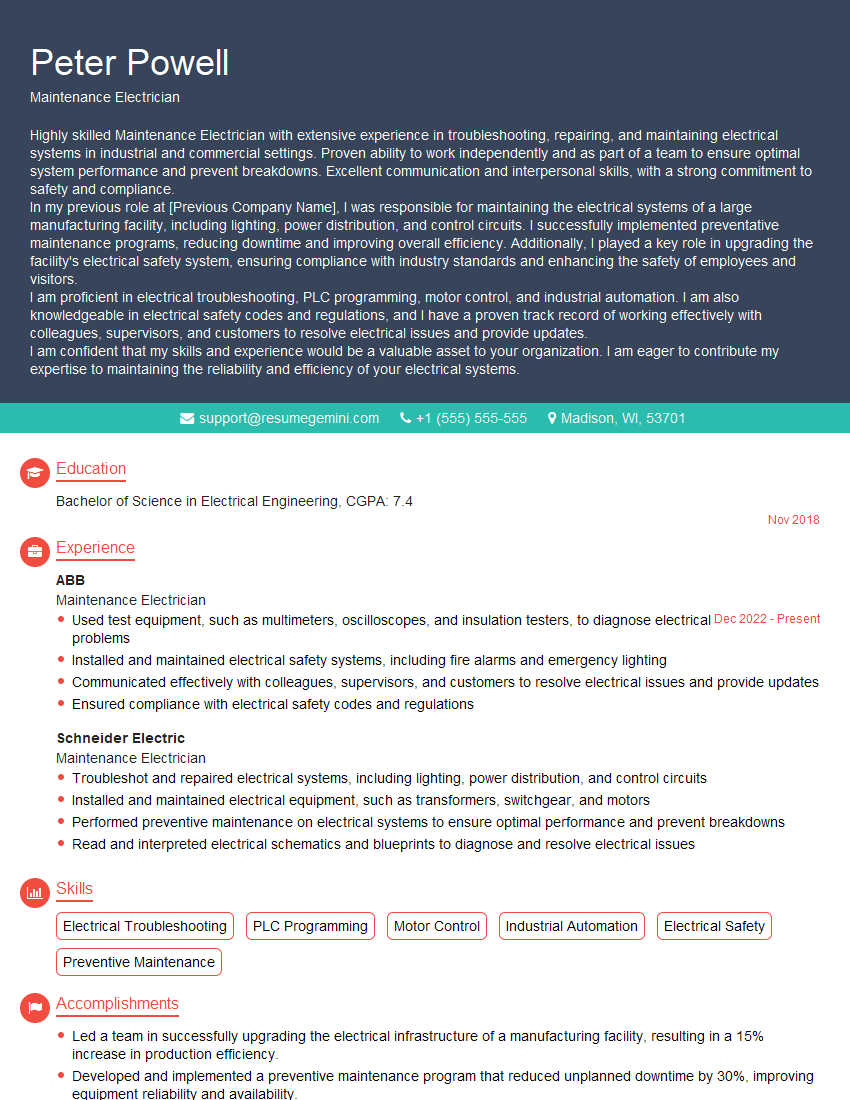
Mastering basic electrical theory is crucial for advancement in many technical fields. A strong understanding of these fundamentals will significantly improve your interview performance and open doors to exciting career opportunities. To maximize your job prospects, it’s vital to present your skills effectively. Creating an ATS-friendly resume is key to getting your application noticed by recruiters. ResumeGemini is a trusted resource to help you build a professional and impactful resume that highlights your expertise in electrical theory. Examples of resumes tailored to showcase basic electrical theory knowledge are available through ResumeGemini, helping you present your qualifications in the best possible light.
Explore more articles
Users Rating of Our Blogs
Share Your Experience
We value your feedback! Please rate our content and share your thoughts (optional).
What Readers Say About Our Blog
Hello,
We found issues with your domain’s email setup that may be sending your messages to spam or blocking them completely. InboxShield Mini shows you how to fix it in minutes — no tech skills required.
Scan your domain now for details: https://inboxshield-mini.com/
— Adam @ InboxShield Mini
Reply STOP to unsubscribe
Hi, are you owner of interviewgemini.com? What if I told you I could help you find extra time in your schedule, reconnect with leads you didn’t even realize you missed, and bring in more “I want to work with you” conversations, without increasing your ad spend or hiring a full-time employee?
All with a flexible, budget-friendly service that could easily pay for itself. Sounds good?
Would it be nice to jump on a quick 10-minute call so I can show you exactly how we make this work?
Best,
Hapei
Marketing Director
Hey, I know you’re the owner of interviewgemini.com. I’ll be quick.
Fundraising for your business is tough and time-consuming. We make it easier by guaranteeing two private investor meetings each month, for six months. No demos, no pitch events – just direct introductions to active investors matched to your startup.
If youR17;re raising, this could help you build real momentum. Want me to send more info?
Hi, I represent an SEO company that specialises in getting you AI citations and higher rankings on Google. I’d like to offer you a 100% free SEO audit for your website. Would you be interested?
Hi, I represent an SEO company that specialises in getting you AI citations and higher rankings on Google. I’d like to offer you a 100% free SEO audit for your website. Would you be interested?
good


