Unlock your full potential by mastering the most common Experience with electrical troubleshooting interview questions. This blog offers a deep dive into the critical topics, ensuring you’re not only prepared to answer but to excel. With these insights, you’ll approach your interview with clarity and confidence.
Questions Asked in Experience with electrical troubleshooting Interview
Q 1. Describe your experience with different types of multimeters and their applications.
Multimeters are essential tools for electrical troubleshooting. I’ve extensive experience using various types, from basic analog models to advanced digital multimeters (DMMs) with features like data logging and capacitance measurement. The choice of multimeter depends on the specific task.
- Analog Multimeters: These are simpler and more rugged, ideal for quick checks in harsh environments. They rely on a needle moving across a calibrated scale to indicate voltage, current, or resistance. I’ve used these for quick continuity checks or verifying basic voltage levels in older systems.
- Digital Multimeters (DMMs): These offer greater precision and a wider range of functions. I regularly utilize DMMs with features like true RMS (Root Mean Square) readings for accurate measurements in AC circuits, diode testing for identifying faulty components, and capacitance measurement for checking capacitors. For example, I once used a DMM’s capacitance function to diagnose a faulty power supply capacitor in a server, preventing a costly downtime.
- Clamp Meters: These are specialized meters with a clamping jaw that measures current without needing to disconnect a wire. This is invaluable for measuring high currents safely in live circuits. I’ve used clamp meters extensively for diagnosing high-current issues in industrial machinery, allowing me to identify overloaded circuits without interrupting operation.
Each type plays a vital role, and selecting the appropriate tool depends entirely on the job at hand. My experience spans the spectrum, ensuring I can efficiently and safely diagnose a wide range of electrical issues.
Q 2. Explain the process of troubleshooting a faulty circuit breaker.
Troubleshooting a faulty circuit breaker involves a methodical approach to ensure both safety and effective resolution. The key is to never assume the breaker is the *only* problem.
- Safety First: Always de-energize the circuit before any physical inspection. This is paramount to prevent electric shock.
- Visual Inspection: Carefully examine the breaker for any signs of damage such as scorch marks, loose wires, or physical damage. A tripped breaker will often have a visible indicator (usually a flipped lever or button).
- Check for Overload: Determine if the breaker is tripping due to an overload. This is usually indicated by multiple devices on that circuit drawing excessive current. I often use a clamp meter here to verify the current draw of individual components.
- Check for Short Circuit: If there are no signs of overload, a short circuit might be the culprit. This would require further investigation, possibly with the use of a multimeter to pinpoint the short circuit location. I might utilize a continuity test to quickly identify a short.
- Test the Breaker: If no obvious problems are found, carefully reset the breaker. If it trips immediately, there’s definitely an underlying fault requiring further investigation. If it stays on, monitor the circuit for a period to make sure the issue is resolved.
- Replace if Necessary: If the breaker is damaged or continues to trip despite addressing other issues, it should be replaced with a breaker of the same amperage and rating.
It’s crucial to remember that a tripped breaker is often a symptom, not the root cause of the problem. Thorough investigation is necessary to prevent recurrence.
Q 3. How do you identify and diagnose short circuits?
Identifying and diagnosing short circuits involves a combination of systematic testing and safety precautions. A short circuit is an unintended low-resistance path for current, often causing excessive heat and potentially fire hazards.
- Safety First: Always de-energize the circuit before any testing.
- Visual Inspection: Look for any visible signs of damage like burnt insulation, melted wires, or sparking. I usually start by carefully inspecting wiring connections for loose or damaged wires.
- Multimeter Continuity Test: With the circuit de-energized, I use a multimeter to test for continuity. This helps to identify a short by detecting an unexpectedly low resistance between conductors that should be insulated from each other. For example, a short circuit between a hot and neutral wire would show near-zero resistance.
- Infrared Thermography (Optional): In some cases, I’ll use an infrared camera to detect hot spots indicating excessive current flow, often pointing to the location of a short circuit.
- Systematic Testing (If no obvious visual signs): If the short is not immediately apparent, I’ll systematically check components and wiring sections. I often start from the suspected area moving toward the circuit breaker, checking the continuity of individual wires and components along the way.
- Trace the Fault: Once the short is identified, I carefully repair or replace the faulty wiring or components, ensuring proper insulation.
Remember, identifying the exact location of a short circuit requires patience and systematic troubleshooting; safety always comes first.
Q 4. What are the common causes of electrical overloads, and how do you address them?
Electrical overloads occur when too much current flows through a circuit exceeding its design capacity. This can lead to overheating, fires, and equipment damage. Common causes include:
- Too Many Devices on One Circuit: Plugging in too many high-power appliances (e.g., space heaters, hair dryers) on a single circuit can overload it. I frequently encounter this in older homes with inadequate circuits.
- Faulty Appliances: A malfunctioning appliance might draw excessive current, overloading the circuit. I often find this using a clamp meter to measure the current draw of individual appliances.
- Short Circuit: As mentioned previously, a short circuit creates an unusually low-resistance path, causing an excessive current flow and overloading the circuit. This often trips a breaker, but not always.
- Incorrect Wiring: Faulty or improperly sized wiring can’t handle the current demand, leading to overheating and potential fires. This is an issue that usually requires professional intervention.
Addressing Overloads:
- Distribute Load: Avoid plugging too many appliances into one circuit. Consider adding additional circuits to spread the load if necessary.
- Repair/Replace Faulty Appliances: Get faulty appliances repaired or replaced immediately. A faulty appliance could cause a serious fire hazard.
- Identify and Repair Short Circuits: Find and rectify any short circuits promptly.
- Upgrade Wiring (If Necessary): In some cases, an electrical upgrade might be needed to increase the circuits’ capacity and handle the increasing demands of modern households.
Proper circuit protection (fuses and circuit breakers) is critical in preventing overload-related damage. Regular inspection and maintenance are key to minimizing these risks.
Q 5. Explain your understanding of Ohm’s Law and its practical application in troubleshooting.
Ohm’s Law is fundamental to electrical troubleshooting. It states the relationship between voltage (V), current (I), and resistance (R): V = I * R.
Practical Applications:
- Calculating Current: If I know the voltage across a component and its resistance, I can calculate the current flowing through it. This is helpful in identifying if a component is drawing excessive current, indicating a possible fault.
- Determining Resistance: By measuring the voltage across a component and the current flowing through it, I can calculate its resistance. If the measured resistance deviates significantly from the expected value, it suggests a component malfunction.
- Voltage Drop Analysis: Ohm’s Law helps analyze voltage drops across components in a circuit. Unusually high voltage drops can point towards faulty connections, excessive resistance in a wire, or a component failing open.
Example: I once encountered a situation where a motor wasn’t starting. By measuring the voltage across the motor terminals and the current draw (using a clamp meter), and applying Ohm’s Law, I determined that the motor’s resistance had increased significantly, suggesting a winding failure.
Ohm’s Law isn’t just a formula; it’s a cornerstone of electrical troubleshooting. Understanding and applying it is crucial for efficient and accurate diagnosis of electrical problems.
Q 6. Describe your experience with interpreting electrical schematics and wiring diagrams.
Interpreting electrical schematics and wiring diagrams is essential for effective troubleshooting. I have extensive experience reading and understanding a wide variety of these diagrams, from simple residential circuits to complex industrial control systems. These diagrams provide a visual representation of the electrical connections in a system.
My Approach:
- Symbol Recognition: I am proficient in recognizing standard symbols for components (resistors, capacitors, switches, etc.) and understanding their function within the circuit.
- Tracing Circuits: I can effectively trace the path of current flow through the circuit, identifying the connections between components and understanding the overall functionality.
- Identifying Key Components: I quickly identify key components such as circuit breakers, fuses, relays, and control systems to better understand the protection and control mechanisms of the system. This is crucial for prioritizing safety during troubleshooting.
- Understanding Logic: I’m comfortable interpreting logic diagrams and relay ladder logic, allowing me to understand the control flow and operation of automation systems.
Practical Example: During the troubleshooting of a faulty lighting system in an office building, I used the schematic to quickly isolate the problem to a specific relay. This allowed me to efficiently repair the lighting circuit without causing further disruption.
Fluency in reading and interpreting electrical drawings is invaluable for accurate and efficient troubleshooting; it saves time, minimizes damage, and prioritizes safety.
Q 7. How do you troubleshoot problems with three-phase power systems?
Troubleshooting three-phase power systems requires specialized knowledge and equipment due to the increased complexity compared to single-phase systems. Three-phase systems typically use three separate voltage phases, 120 degrees apart, which creates a more stable and efficient power delivery.
Common Issues and Troubleshooting Steps:
- Voltage Imbalance: This occurs when the voltage across the three phases is not equal. I use a three-phase multimeter to measure the voltage between phases and identify the imbalance. The cause could be a faulty transformer, loose connections, or unbalanced loads. Correction might involve adjusting loads or repairing faulty components.
- Phase Loss: This indicates one or more phases are not receiving power. It often results in equipment malfunction or failure. I would first use a multimeter to identify the missing phase(s) and then investigate the cause, such as a blown fuse, tripped breaker, or a problem in the distribution system.
- Motor Problems: Three-phase motors are common in industrial settings. Troubleshooting often involves checking for proper rotation, current draw, and insulation resistance using a motor analyzer or megger. High current might indicate a winding fault, while low current may mean a mechanical issue. A megger tests insulation to check for possible ground faults.
- Overheating: Three-phase systems can overheat if there are problems like current imbalances or excessive loads. I use infrared cameras and thermal imaging techniques to identify hot spots in the system.
Safety Precautions: Working with three-phase systems necessitates a high degree of safety awareness. Lockout/Tagout procedures are crucial to ensure the system is completely de-energized before commencing any maintenance or troubleshooting activities. Specialized training and equipment are essential for working safely with these systems.
Q 8. Explain your process for safely isolating electrical circuits before working on them.
Isolating electrical circuits before working on them is paramount for safety. My process always begins with a visual inspection, ensuring I understand the system layout and identifying the specific circuit requiring attention. Then, I follow a rigorous, multi-step procedure:
Lockout/Tagout (LOTO): This is the most crucial step. I will locate the appropriate disconnect switch or breaker for the circuit and securely lock it in the OFF position, attaching my personal lockout tag to prevent accidental energization. This is never bypassed.
Verification: After locking out the breaker, I always use a non-contact voltage tester to verify that the circuit is truly de-energized. This double-checks the LOTO procedure and eliminates any doubt.
Grounding: Depending on the voltage and application, I’ll use an appropriately rated grounding device to connect the circuit to earth ground. This provides an additional layer of safety by discharging any residual energy.
Double-Check: Before starting any work, I perform another non-contact voltage test to confirm de-energization. Safety is paramount, and repetition is key.
For example, working on a lighting circuit in a commercial building, I’d first identify the breaker in the panel, then lock it out, test with my non-contact voltage tester, ground the circuit at the fixture, and finally, test again before beginning the repair.
Q 9. What safety precautions do you take when working with high-voltage equipment?
Working with high-voltage equipment demands extreme caution and adherence to strict safety protocols. My approach is always proactive and preventative. Key precautions include:
Specialized PPE (Personal Protective Equipment): This includes insulated gloves rated for the voltage level, safety glasses, arc-flash protective clothing, and appropriate footwear. I always ensure my PPE is in good condition and correctly sized.
Trained Personnel: I never work alone on high-voltage systems. Having a second person present allows for better oversight and immediate assistance if an incident occurs. Ideally, we conduct a thorough job briefing prior to commencing work.
Safety Barriers and Warning Signs: Appropriately marked barriers and warning signs should be in place to prevent unauthorized access to the area during high-voltage work.
Arc Flash Hazard Analysis: Before starting any high-voltage job, I refer to the appropriate arc flash study to determine the potential hazards and select the right PPE to mitigate the risks.
Specialized Tools: I use only tools with insulated handles rated for the voltage level, and always ensure they are in good repair.
For instance, when working on a 480V motor control center, I’d wear appropriate arc flash rated clothing, use insulated tools, and have a qualified colleague act as a spotter while employing all the lockout/tagout procedures mentioned previously.
Q 10. How do you troubleshoot problems with motors (AC/DC)?
Troubleshooting AC and DC motors involves a systematic approach. I usually start with visual inspection, then proceed with systematic testing:
Visual Inspection: I check for obvious signs of damage, such as burned wiring, loose connections, or physical damage to the motor or its components.
Power Supply Check: I verify the motor is receiving the correct voltage and amperage using a multimeter. This involves checking both at the supply and at the motor terminals.
Motor Winding Resistance Test: Using a multimeter, I check the resistance of the motor windings for any shorts or open circuits. Significant deviation from the manufacturer’s specifications indicates a problem.
Insulation Resistance Test (Megger): A megger test measures the insulation resistance of the motor windings to ground. Low resistance suggests insulation breakdown.
Load Test: If possible and safe, I’ll run the motor under load to observe its performance. Unusual sounds, vibrations, or excessive heating are signs of problems.
Control Circuit Analysis: For AC motors, I may check the motor starter components (relays, contactors, overload protection) to ensure proper operation. For DC motors, I’ll examine the control circuitry and components like the speed controller.
For example, a humming AC motor might indicate bearing wear, while a noisy DC motor might have issues with its commutator or brushes.
Q 11. Describe your experience with PLC troubleshooting.
My PLC troubleshooting experience is extensive. I approach it using a structured methodology:
Understand the System: I begin by thoroughly reviewing the PLC program, I/O configuration, and system documentation to get a clear understanding of how the system is supposed to function.
Identify the Problem: I precisely define the problem, using the alarm logs and operator feedback as my starting point. I’ll use the ladder logic diagrams to visually inspect potential points of failure.
Isolate the Fault: I systematically check the inputs, outputs, and internal logic of the PLC using diagnostic tools such as the PLC’s programming software and monitoring capabilities. This may involve checking physical wiring to ensure integrity.
Test and Verify: After making a change or repair, I thoroughly test the system to confirm the issue is resolved and that no new problems have been introduced. I rely on simulated inputs and monitored outputs.
Document the Solution: Once the problem is solved, I meticulously document the troubleshooting steps, the root cause, and the solution, including any modifications made to the PLC program or hardware.
For instance, a recent project involved a PLC controlling a conveyor system. Using the PLC’s diagnostic tools, I traced a faulty output module causing the conveyor to stop unexpectedly. Replacing the module resolved the problem.
Q 12. How do you troubleshoot issues with control systems?
Control system troubleshooting requires a holistic approach. My strategy includes:
Systematic Approach: I work through the control system layer by layer, starting from the simplest components and progressing toward more complex ones. This might involve examining sensors, actuators, the PLC, and the HMI (Human-Machine Interface).
Signal Tracing: I trace the signals throughout the system to pinpoint where the problem originates. This can involve using multimeters, oscilloscopes, and logic analyzers.
Data Analysis: I analyze the data logged by the control system to identify patterns or trends that indicate a problem. This often involves looking at historical data and system logs.
Process Understanding: Having a thorough understanding of the underlying process the control system manages is essential. This helps to understand the context of any abnormalities.
Simulation: When possible, I use simulation techniques to test and verify changes made to the control system.
For example, if a process is not achieving the desired output, I would look at sensor readings, actuator commands, and PLC logic to diagnose if the issue stems from faulty sensors, faulty actuators, or incorrect control logic.
Q 13. What are your methods for documenting troubleshooting procedures?
Thorough documentation is crucial for effective troubleshooting and future maintenance. My methods include:
Detailed Troubleshooting Reports: I create detailed reports that include a clear description of the problem, the steps taken to diagnose the problem, the root cause of the problem, the solution implemented, and any preventative measures taken. These reports typically include images, schematics, and circuit diagrams.
Schematic Diagrams: I use clear schematic diagrams to illustrate the system’s architecture and identify the specific components involved in the problem.
Digital Tools: I often utilize digital tools such as spreadsheets, databases, or dedicated CMMS (Computerized Maintenance Management System) software to store troubleshooting procedures and documentation. This ensures easy access and retrieval of information.
Photographs and Videos: For complex or unique issues, capturing visual evidence is helpful for future reference.
My documentation practices contribute to knowledge sharing and efficient problem solving, improving response time and minimizing downtime.
Q 14. Explain your experience with using diagnostic software for electrical systems.
I have extensive experience using various diagnostic software for electrical systems. This includes PLC programming software (like RSLogix, Studio 5000), motor drive diagnostic tools, and specialized software for power quality analysis. My experience involves:
PLC Programming Software: I utilize these tools to monitor PLC operation, review program logic, and examine I/O data, which helps pinpoint the source of malfunctions within the system.
Motor Drive Diagnostic Software: This is useful for checking parameters, analyzing fault codes, and conducting performance tests on variable frequency drives (VFDs). This often helps identify mechanical problems reflected in electrical data.
Power Quality Analyzers: This specialized software aids in the detection of power disturbances like voltage sags, surges, and harmonics, which can be critical in diagnosing intermittent electrical faults.
Data Acquisition and Analysis: Many diagnostic systems permit data acquisition and logging, allowing for in-depth analysis of system behavior over time, helping pinpoint trends that might otherwise be overlooked.
Using these tools allows for a much more precise and efficient troubleshooting process, often reducing the time needed for repair significantly.
Q 15. How do you prioritize troubleshooting tasks in a time-sensitive situation?
Prioritizing troubleshooting tasks in a time-sensitive situation requires a systematic approach. I use a combination of urgency and impact assessment. First, I identify all affected systems or components and categorize them by criticality – which systems cause the most significant disruption if down? I then assess the potential impact of each problem, considering factors such as safety hazards, production downtime, and financial losses. This allows me to create a ranked list of tasks, addressing the most critical issues first. For example, a power failure affecting a critical server would take precedence over a flickering light in a rarely used area. I also consider the complexity of each task. A simple fix is prioritized over a complex one, even if the impact isn’t as drastically different, unless safety is at risk. This approach allows for efficient resource allocation and minimizes downtime.
Career Expert Tips:
- Ace those interviews! Prepare effectively by reviewing the Top 50 Most Common Interview Questions on ResumeGemini.
- Navigate your job search with confidence! Explore a wide range of Career Tips on ResumeGemini. Learn about common challenges and recommendations to overcome them.
- Craft the perfect resume! Master the Art of Resume Writing with ResumeGemini’s guide. Showcase your unique qualifications and achievements effectively.
- Don’t miss out on holiday savings! Build your dream resume with ResumeGemini’s ATS optimized templates.
Q 16. Describe a time you had to troubleshoot a complex electrical problem. What was your approach?
I once encountered a complex problem involving intermittent power outages in a large manufacturing facility. The outages were unpredictable, affecting different sections of the plant at various times. My approach involved a systematic investigation. First, I gathered information: I spoke with operators, reviewed maintenance logs, and checked the facility’s electrical schematics. This revealed no immediately obvious cause. Next, I employed a divide-and-conquer strategy, systematically checking each section of the electrical system, starting with the main power supply. I used a combination of multimeters, clamp meters, and thermal imaging cameras to check voltage levels, current draw, and temperatures. This helped me identify a faulty connection within a large distribution panel, specifically a loose connection on a high-voltage bus bar. The intermittent nature of the problem was due to the loose connection making and breaking contact intermittently as the panel vibrated due to nearby machinery. Tightening the connection resolved the issue, but it highlighted the importance of thorough inspections and preventative maintenance.
Q 17. What are your preferred methods for testing electrical components?
My preferred methods for testing electrical components depend on the specific component and the suspected fault. For basic measurements like voltage and current, I rely on a high-quality digital multimeter (DMM). I use clamp meters to measure current without interrupting the circuit, particularly useful for high-current applications. For continuity checks, the DMM’s continuity test mode is invaluable in detecting broken wires or faulty connections. When dealing with high-voltage systems or sensitive electronics, I utilize specialized test equipment such as oscilloscopes for waveform analysis and insulation resistance testers to check for insulation breakdown. Always remember safety first – using appropriate personal protective equipment (PPE) is critical when working with electricity.
Q 18. How do you handle situations where you are unable to isolate the source of an electrical problem?
When I can’t isolate the source of an electrical problem, I escalate and collaborate. First, I meticulously document all my findings, including measurements, observations, and troubleshooting steps taken. Then, I consult with experienced colleagues or specialists for a second opinion. In some cases, bringing in a specialized testing company might be necessary for advanced diagnostics such as infrared thermography or power quality analysis. Sometimes, the issue might be intermittent or environmental, requiring extended monitoring. I would set up a monitoring system to continuously record relevant data to see if the problem shows up again and to track any correlations with environmental factors. Thorough documentation at every stage is crucial for effective collaboration and problem resolution.
Q 19. Explain your understanding of grounding and its importance in electrical safety.
Grounding is a critical safety feature in electrical systems. It provides a low-resistance path for fault currents to flow to the earth, preventing dangerous voltage buildup on exposed conductive surfaces. Imagine grounding as a safety valve: If a fault occurs – like a short circuit – the current is safely diverted to the ground, rather than potentially causing a shock or fire. Without proper grounding, even minor faults could result in dangerous voltages on equipment casings. A properly grounded system minimizes the risk of electric shock, reduces the risk of fire hazards, and protects sensitive equipment from voltage surges. Grounding systems typically involve ground rods driven into the earth, connected to the system’s grounding busbar, and bonded to all metal enclosures.
Q 20. How do you ensure the accuracy of your troubleshooting measurements?
Ensuring accuracy in troubleshooting measurements is paramount. I start by calibrating my test equipment according to the manufacturer’s instructions before each use. I make sure the test leads are properly connected and free of damage. When measuring voltage, I always ensure the meter is set to the correct range to avoid damage to the meter and inaccurate readings. For current measurements, I use appropriate clamp meters and ensure proper contact with the conductor. Multiple measurements are taken to ensure consistency and detect any potential anomalies. Finally, I always double-check my results against the expected values, considering factors like tolerances and expected variations in the system. When dealing with complex circuits or safety-critical applications, it’s vital to have another technician verify the readings.
Q 21. Describe your experience with different types of sensors and their applications in troubleshooting.
My experience includes using various sensors in electrical troubleshooting, depending on the nature of the problem. Temperature sensors (thermocouples, RTDs) help identify overheating components, which can indicate potential faults. Current sensors (current transformers, hall-effect sensors) monitor current draw, helping pinpoint overloaded circuits or faulty devices. Voltage sensors are used for precise voltage measurements across components. Vibration sensors can detect mechanical problems that might affect electrical components, such as loose connections. In more advanced scenarios, I’ve used specialized sensors like acoustic emission sensors to detect partial discharges in high-voltage equipment, providing early warnings of insulation degradation. The choice of sensor depends on the specific application and the type of problem being investigated. For example, a temperature sensor would be more relevant in investigating a motor that’s not operating correctly, while a current sensor could reveal issues with overcurrent protection devices.
Q 22. Explain your experience with using thermal imaging cameras for electrical troubleshooting.
Thermal imaging cameras are invaluable tools for electrical troubleshooting. They detect infrared radiation emitted by components, allowing us to visualize temperature variations. Hot spots, often indicative of overheating and potential failure, become readily apparent. For example, a loose connection exhibiting high resistance will generate significant heat, easily identifiable as a bright area on the thermal image. This allows for proactive identification of problems before they escalate into costly failures or safety hazards.
In my experience, I’ve used thermal imaging to pinpoint failing capacitors in power supplies, identify overloaded circuits before a breaker tripped, and even detect arcing within a junction box before a fire could start. The images provide a clear, visual representation of the problem area, guiding the repair process efficiently. I often compare it to having ‘x-ray vision’ for electrical systems.
Q 23. How do you troubleshoot issues with electrical wiring in buildings?
Troubleshooting electrical wiring in buildings requires a systematic approach. I begin with a visual inspection, checking for obvious damage, loose connections, or exposed wires. Then, I use a voltage tester to verify power at various points within the circuit, isolating the section with the problem. If there’s a short circuit, a multimeter will help pin point the location by measuring resistance. I always follow safety procedures, including de-energizing the circuit before directly working on the wires.
For instance, I once worked on a building where flickering lights pointed to a faulty connection in the attic. Through careful tracing of the wiring and using the voltage tester, we found a corroded connection in a junction box, resulting in a voltage drop and flickering lights. Proper cleaning and secure connections resolved the problem.
Q 24. What is your experience with different types of electrical connectors and their troubleshooting?
My experience encompasses a wide range of electrical connectors, from simple wire nuts and crimp connectors to more specialized types like Anderson Powerpole connectors (often used in solar and automotive applications) and various industrial connectors like Deutsch and Amphenol. Troubleshooting these connectors focuses on identifying loose connections, corrosion, or damage to the connector itself.
A common problem is corrosion, especially in outdoor environments. I’ve found that proper cleaning and the application of dielectric grease can often resolve connection issues. Sometimes, the connectors themselves are compromised and require replacement. For example, a poorly crimped connector can lead to intermittent or complete failure of the circuit. Visual inspection is key. If the connector is damaged, it needs to be replaced for safety and reliable operation.
Q 25. How do you stay updated on the latest electrical codes and safety regulations?
Staying updated on electrical codes and safety regulations is critical for my profession. I regularly subscribe to industry publications like Electrical Contractor magazine and attend workshops and seminars offered by organizations like NFPA (National Fire Protection Association). I also actively participate in online forums and communities to stay informed about emerging technologies and best practices.
Understanding the latest codes is not just about compliance; it’s about ensuring safety and preventing potential hazards. The building codes change frequently so it is imperative to stay up-to-date and follow all guidelines. For example, recent updates regarding arc-flash protection have greatly influenced how I approach high-voltage systems. Continual learning is fundamental to maintaining a high level of competence and expertise.
Q 26. Describe your experience with working on both low voltage and high voltage systems.
I’ve worked extensively with both low-voltage and high-voltage systems. Low-voltage work, such as home wiring or data cabling, often involves troubleshooting issues like faulty outlets, network connectivity problems, or damaged wiring. High-voltage systems, on the other hand, require stricter safety protocols and specialized equipment. This includes working on large industrial machinery, power distribution systems, and high-power lighting.
The approach differs significantly. Low-voltage troubleshooting often relies on basic multimeters and voltage testers. High-voltage work demands specialized tools, personal protective equipment (PPE), like arc-flash suits, and a deep understanding of safety procedures. A crucial difference is the potential for serious injury or death when dealing with high-voltage, necessitating a cautious and thorough approach. Experience in both aspects gives me a broad perspective and skillset.
Q 27. How do you handle unexpected electrical issues during maintenance or repairs?
Unexpected electrical issues demand a calm and methodical response. My first priority is always safety. I immediately de-energize the affected circuit if possible, and if not, I establish a safe working distance. I then proceed with a thorough assessment of the situation, utilizing appropriate diagnostic tools to identify the root cause of the problem. Prioritizing safety measures is paramount, such as lockout/tagout procedures, ensuring nobody is at risk before starting any repairs.
For example, if a breaker trips unexpectedly during maintenance, I wouldn’t rush to reset it. I would systematically check the circuit for overloads, shorts, or other potential problems. Only after I’ve thoroughly investigated and addressed the underlying issue would I consider resetting the breaker. A hasty reset could lead to further damage or injury.
Q 28. What is your experience with different types of circuit protection devices and their applications?
I’m familiar with various circuit protection devices, including circuit breakers, fuses, ground fault circuit interrupters (GFCIs), and arc fault circuit interrupters (AFCIs). Circuit breakers provide overcurrent protection, tripping when current exceeds a predefined threshold. Fuses operate similarly, but are one-time use devices. GFCIs protect against ground faults, which can be lethal. AFCIs detect and interrupt potentially hazardous arcing faults that can cause fires.
The selection of the appropriate device depends on the specific application and the type of protection required. For instance, GFCIs are mandatory in bathrooms and kitchens to mitigate the risk of electric shock. AFCIs are increasingly common in bedrooms and living areas to reduce the risk of electrical fires. Understanding their applications and limitations is crucial for ensuring both safety and proper operation of electrical systems.
Key Topics to Learn for Electrical Troubleshooting Interviews
- Fundamental Electrical Theory: Understanding Ohm’s Law, Kirchhoff’s Laws, and basic circuit analysis is crucial for diagnosing electrical problems. Brush up on series and parallel circuits, voltage, current, and resistance.
- Common Electrical Faults: Familiarize yourself with identifying and troubleshooting short circuits, open circuits, ground faults, and overloads. Practice recognizing the symptoms and causes of each.
- Testing and Measurement Techniques: Master the use of multimeters (both analog and digital) to measure voltage, current, and resistance. Understand how to use other diagnostic tools like clamp meters and circuit testers.
- Safety Procedures: Review and understand proper safety protocols for working with electricity, including lockout/tagout procedures and personal protective equipment (PPE).
- Troubleshooting Methodologies: Practice systematic troubleshooting approaches, such as the “divide and conquer” method or using flowcharts to isolate problems efficiently. Develop your ability to interpret schematic diagrams and wiring layouts.
- Specific Equipment Knowledge: Depending on the role, focus on troubleshooting specific equipment like motors, transformers, control systems, or industrial power distribution systems. Highlight your experience with any relevant technologies.
- Preventive Maintenance: Demonstrate understanding of preventative maintenance procedures to minimize electrical failures and extend equipment lifespan. This showcases proactive problem-solving skills.
- Documentation and Reporting: Practice documenting troubleshooting steps, findings, and solutions clearly and concisely. This is a critical aspect of many electrical roles.
Next Steps
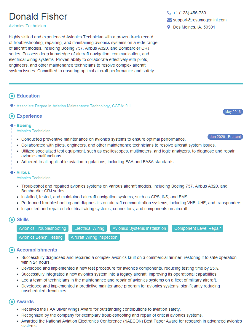
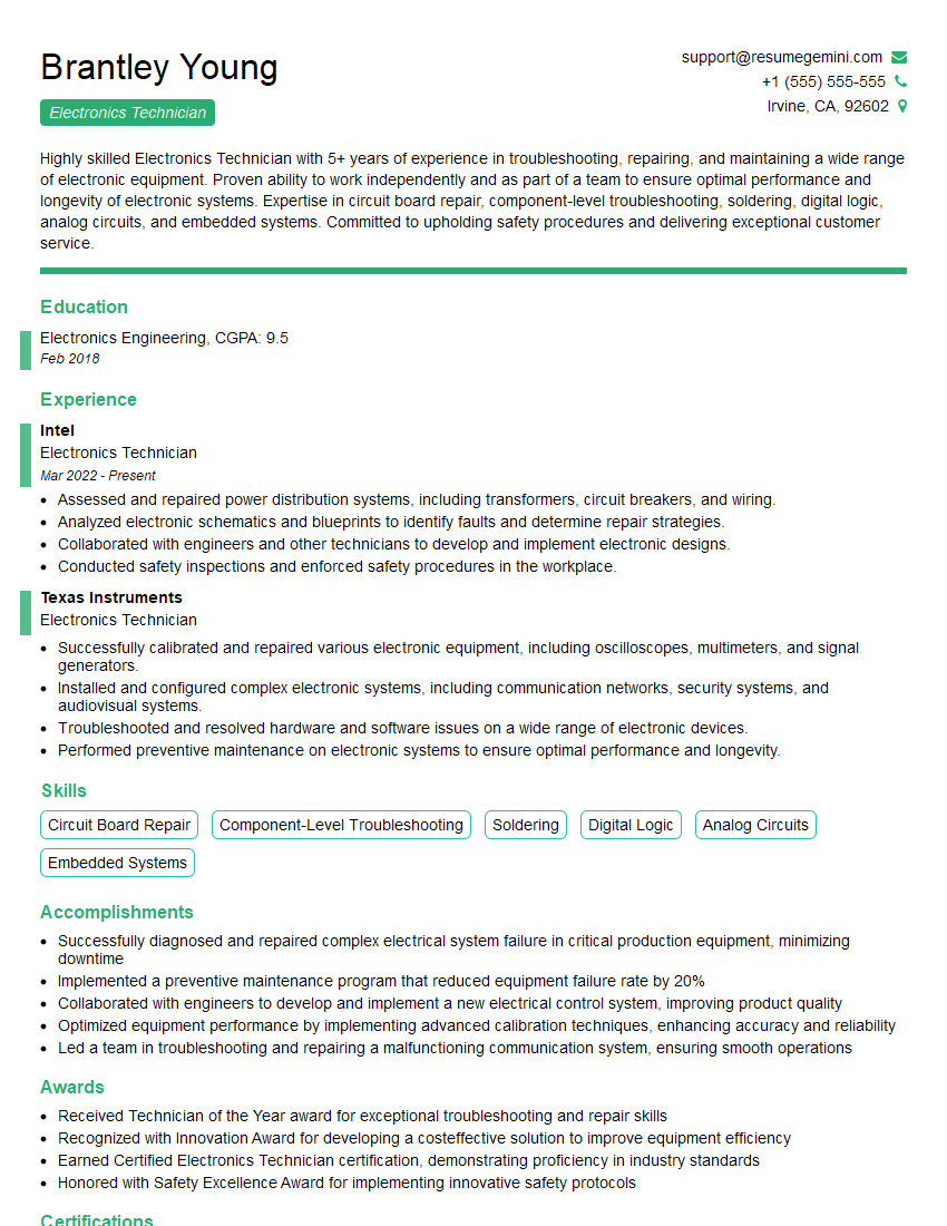
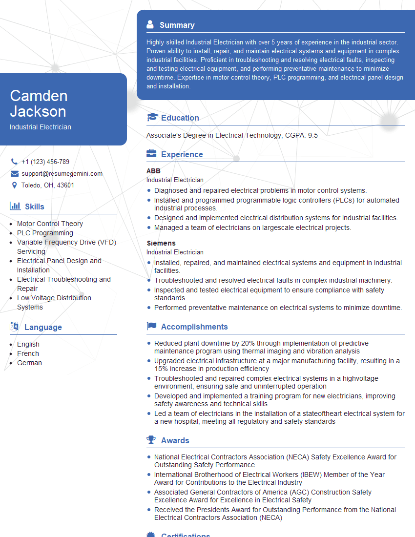
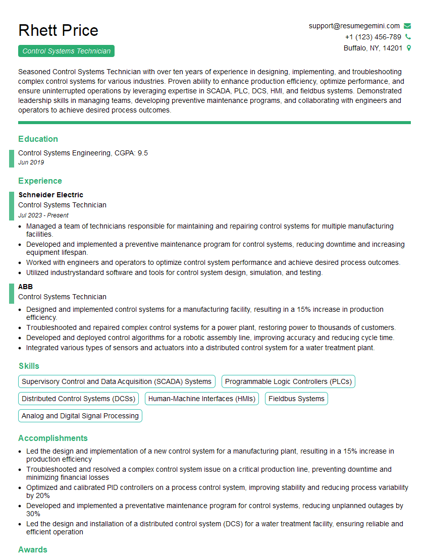
Mastering electrical troubleshooting is essential for career advancement in many technical fields, opening doors to higher-paying roles and increased responsibility. A strong resume is your key to unlocking these opportunities. Make sure your resume is ATS-friendly to ensure it gets noticed by recruiters. ResumeGemini is a trusted resource to help you create a professional and impactful resume that highlights your skills and experience. We provide examples of resumes tailored to highlight experience in electrical troubleshooting to help you build the perfect application.
Explore more articles
Users Rating of Our Blogs
Share Your Experience
We value your feedback! Please rate our content and share your thoughts (optional).
What Readers Say About Our Blog
Hello,
We found issues with your domain’s email setup that may be sending your messages to spam or blocking them completely. InboxShield Mini shows you how to fix it in minutes — no tech skills required.
Scan your domain now for details: https://inboxshield-mini.com/
— Adam @ InboxShield Mini
Reply STOP to unsubscribe
Hi, are you owner of interviewgemini.com? What if I told you I could help you find extra time in your schedule, reconnect with leads you didn’t even realize you missed, and bring in more “I want to work with you” conversations, without increasing your ad spend or hiring a full-time employee?
All with a flexible, budget-friendly service that could easily pay for itself. Sounds good?
Would it be nice to jump on a quick 10-minute call so I can show you exactly how we make this work?
Best,
Hapei
Marketing Director
Hey, I know you’re the owner of interviewgemini.com. I’ll be quick.
Fundraising for your business is tough and time-consuming. We make it easier by guaranteeing two private investor meetings each month, for six months. No demos, no pitch events – just direct introductions to active investors matched to your startup.
If youR17;re raising, this could help you build real momentum. Want me to send more info?
Hi, I represent an SEO company that specialises in getting you AI citations and higher rankings on Google. I’d like to offer you a 100% free SEO audit for your website. Would you be interested?
Hi, I represent an SEO company that specialises in getting you AI citations and higher rankings on Google. I’d like to offer you a 100% free SEO audit for your website. Would you be interested?
good

