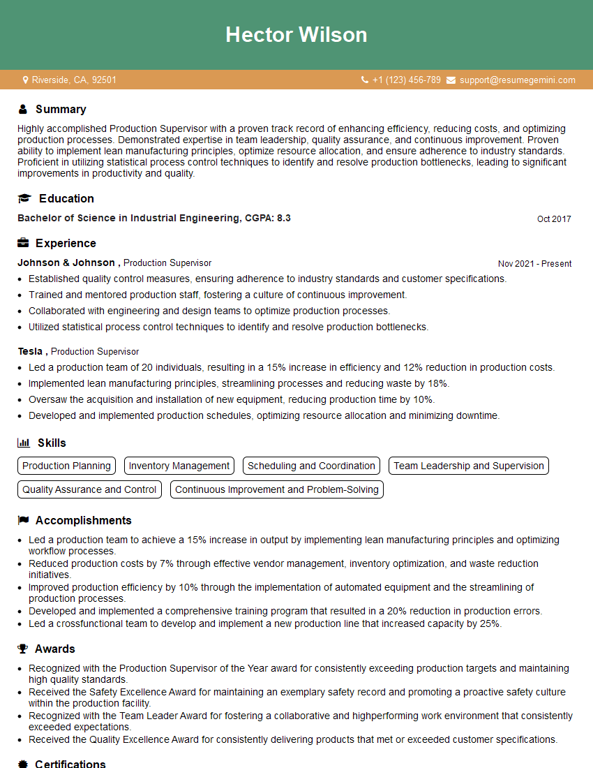
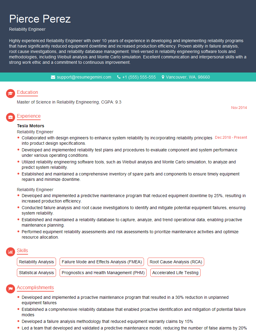
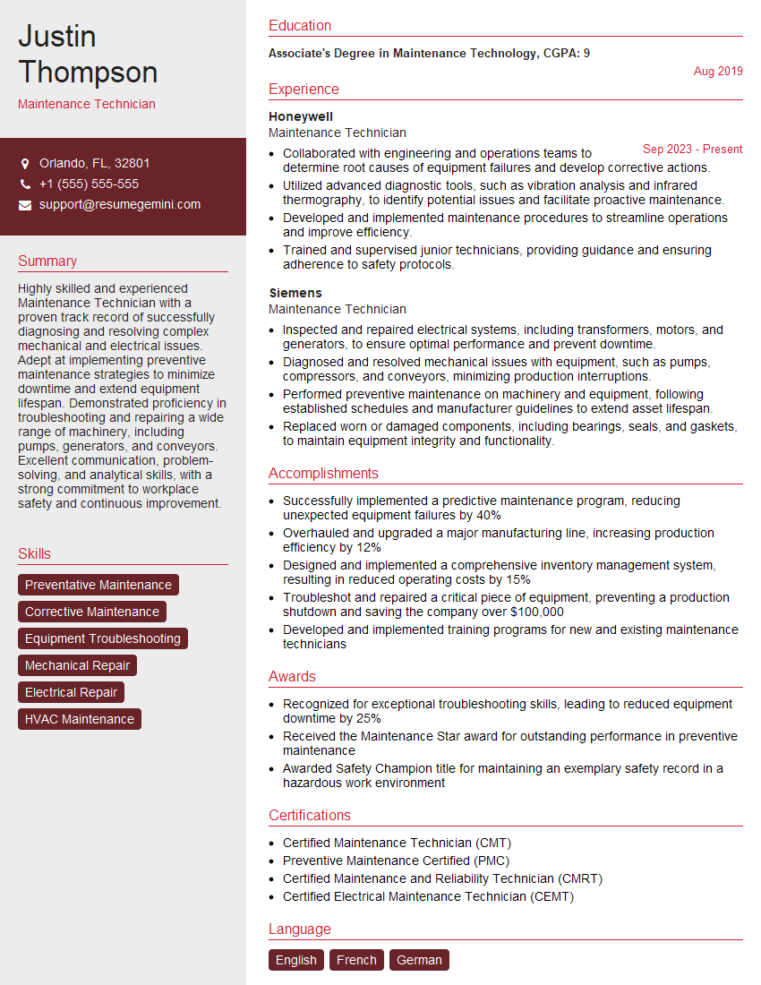
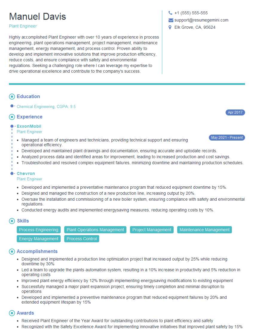
Unlock your full potential by mastering the most common Basic Mechanical Knowledge and ProblemSolving Skills interview questions. This blog offers a deep dive into the critical topics, ensuring you’re not only prepared to answer but to excel. With these insights, you’ll approach your interview with clarity and confidence.
Questions Asked in Basic Mechanical Knowledge and ProblemSolving Skills Interview
Q 1. Explain Newton’s three laws of motion.
Newton’s three laws of motion are fundamental principles in classical mechanics that describe the relationship between a body and the forces acting upon it and its motion in response to those forces.
- Newton’s First Law (Inertia): An object at rest stays at rest and an object in motion stays in motion with the same speed and in the same direction unless acted upon by an unbalanced force. Think of a hockey puck sliding on frictionless ice – it would continue moving indefinitely in a straight line. This law highlights the concept of inertia, the tendency of an object to resist changes in its state of motion.
- Newton’s Second Law (F=ma): The acceleration of an object is directly proportional to the net force acting on the object, is in the same direction as the net force, and is inversely proportional to the mass of the object. This is often expressed as the equation
F = ma, where F is force, m is mass, and a is acceleration. For example, pushing a shopping cart requires less force to accelerate than pushing a car, due to the car’s significantly greater mass. The heavier the object, the greater the force required to achieve a certain acceleration. - Newton’s Third Law (Action-Reaction): For every action, there is an equal and opposite reaction. When one object exerts a force on a second object, the second object simultaneously exerts a force equal in magnitude and opposite in direction on the first object. Consider a rocket launching; the rocket expels hot gas downwards (action), and the gas exerts an equal and opposite upward force on the rocket (reaction), propelling it into space.
Q 2. Describe the different types of simple machines.
Simple machines are basic mechanical devices that use a single applied force to do work against a single load force. They make work easier by changing the magnitude or direction of the force. The six classic types are:
- Lever: A rigid bar that pivots around a fixed point (fulcrum). Examples include seesaws, crowbars, and even your forearm.
- Wheel and Axle: A wheel attached to a smaller axle, allowing for easier rotation. Examples include doorknobs, steering wheels, and gears.
- Pulley: A wheel with a groove around its circumference that is used to change the direction or magnitude of a force. Examples include cranes and elevators.
- Inclined Plane: A flat surface tilted at an angle. Ramps, stairs, and even a slide are all examples.
- Wedge: An inclined plane that moves. Knives, axes, and chisels are examples.
- Screw: An inclined plane wrapped around a cylinder. Screws, bolts, and even a jar lid are all examples.
Understanding simple machines is fundamental in designing and analyzing more complex mechanical systems.
Q 3. What is the difference between stress and strain?
Stress and strain are both related to the deformation of a material under load, but they represent different aspects:
- Stress: Stress is the internal force per unit area within a material that arises in response to an externally applied force. It’s a measure of how much force the material is experiencing internally. It’s calculated as
Stress = Force / Area. The units are typically Pascals (Pa) or pounds per square inch (psi). - Strain: Strain is a measure of the deformation of a material caused by stress. It’s the ratio of the change in dimension to the original dimension. Strain is dimensionless; it’s a ratio of two lengths. For example, if a 10cm long rod stretches to 10.1cm, the strain is (10.1-10)/10 = 0.01.
The relationship between stress and strain is crucial for understanding a material’s mechanical properties and predicting its behavior under various loading conditions. The stress-strain curve is a graphical representation of this relationship and is unique for each material. It shows the material’s elastic limit (yielding point) and ultimate tensile strength.
Q 4. Explain the concept of torque and its significance.
Torque, also known as the moment of force, is a measure of how much a force acting on an object causes that object to rotate. It is calculated as the product of the force and the perpendicular distance from the axis of rotation to the line of action of the force. The formula is: Torque = Force x Distance. The units are typically Newton-meters (Nm) or pound-feet (lb-ft).
Significance: Torque is crucial in many engineering applications. In vehicles, engine torque determines the rotational force available to accelerate the wheels. In fastening systems, torque ensures bolts and nuts are tightened correctly to prevent loosening or failure. It is also critical in the design of rotating machinery like turbines and gearboxes. Insufficient torque could lead to stripped threads or a malfunctioning system, while excessive torque could cause component damage.
Q 5. What are the different types of gears and their applications?
Gears are toothed wheels that mesh together to transmit rotational motion and torque between shafts. Different types of gears are used depending on the application’s specific requirements for speed, torque, and efficiency.
- Spur Gears: These are the most common type, with straight teeth parallel to the axis of rotation. They are simple to manufacture but can be noisy at high speeds.
- Helical Gears: These have angled teeth, providing smoother and quieter operation than spur gears, especially at higher speeds. They also transmit higher loads more effectively.
- Bevel Gears: These gears transmit power between shafts that intersect at an angle, commonly used in differential systems in cars.
- Worm Gears: These consist of a worm (screw-like gear) and a worm wheel. They are used for high speed reduction with relatively low backlash.
- Rack and Pinion Gears: These convert rotational motion into linear motion or vice versa, commonly used in steering systems.
The choice of gear type depends on factors such as speed ratio, power transmission, space constraints, noise levels, and cost.
Q 6. Describe the working principle of a hydraulic system.
Hydraulic systems use pressurized fluid (usually oil) to transmit power from one location to another. They function based on Pascal’s principle, which states that pressure applied to an enclosed fluid is transmitted undiminished to every portion of the fluid and the walls of the containing vessel.
Working Principle: A hydraulic system typically consists of a pump, a reservoir, valves, and actuators (cylinders). The pump pressurizes the fluid, which is then directed by valves to the actuators. The actuators convert the fluid pressure into mechanical force, allowing for the movement of heavy loads or the precise control of position. A simple example is a hydraulic jack, where a small force applied to a small piston generates a large force on a larger piston, lifting a heavy object.
Hydraulic systems are widely used in heavy machinery, construction equipment, and aircraft due to their ability to generate high forces and precise control.
Q 7. Explain the concept of thermal expansion.
Thermal expansion is the tendency of matter to change its volume in response to changes in temperature. Most materials expand when heated and contract when cooled. This is because increased temperature increases the kinetic energy of the atoms or molecules, causing them to vibrate more vigorously and thus occupy more space.
Factors Affecting Thermal Expansion: The amount of expansion depends on several factors including the material’s coefficient of thermal expansion (a material-specific property), the change in temperature, and the original dimensions of the object. Different materials expand at different rates; for example, steel expands less than aluminum for the same temperature change.
Practical Applications and Considerations: Thermal expansion must be considered in many engineering applications, such as bridge design (expansion joints accommodate changes in length) and precision manufacturing (accounting for changes in component dimensions due to temperature variations during manufacturing processes). Ignoring thermal expansion can lead to structural failure or malfunctions.
Q 8. What is the difference between static and dynamic friction?
Friction is the resistance to motion between surfaces in contact. Static friction is the force that prevents two surfaces from sliding past each other when they are at rest. Dynamic (or kinetic) friction is the force resisting motion when two surfaces are already sliding past each other.
Think of a block sitting on a table. To get it moving, you need to overcome static friction. Once it’s moving, the force required to keep it moving is dynamic friction, which is typically less than static friction. This is why it’s often easier to keep something moving than to start it moving.
In simpler terms: Static friction = ‘sticking’ friction; Dynamic friction = ‘sliding’ friction. The coefficient of static friction (μs) is usually higher than the coefficient of dynamic friction (μk).
Q 9. How do you calculate the mechanical advantage of a lever?
The mechanical advantage (MA) of a lever is the ratio of the output force (the force the lever exerts on the object) to the input force (the force you apply to the lever). It essentially tells you how much the lever multiplies your effort.
The formula for the mechanical advantage of a lever is:
MA = Output Force / Input Force = Length of Effort Arm / Length of Load Arm
Where:
- Output Force is the force exerted on the load (object being moved).
- Input Force is the force applied to the lever.
- Length of Effort Arm is the distance from the fulcrum (pivot point) to the point where the input force is applied.
- Length of Load Arm is the distance from the fulcrum to the point where the output force acts on the load.
For example, if you apply 10N of force to a lever arm 2 meters long and lift a 20N weight located 1 meter from the fulcrum, the mechanical advantage is 20N / 10N = 2, or alternatively, 2m / 1m = 2.
Q 10. Explain the concept of power transmission.
Power transmission is the process of transferring mechanical power from one location to another, or from one machine to another. This often involves changing the speed, torque, or direction of the power. It’s crucial in many applications, from simple hand tools to complex industrial machinery.
Common methods of power transmission include:
- Belts and Pulleys: Used to transfer power between shafts that are relatively far apart. Varying pulley diameters allows for speed changes.
- Gears: Transfer power between shafts and provide mechanical advantage through gear ratios. They also allow for changes in speed and direction.
- Chains and Sprockets: Similar to belts and pulleys, but offer greater power transmission capability and better grip.
- Shafts and Couplings: Transmit power through direct connection; couplings allow for flexibility and disconnection.
- Hydraulic and Pneumatic Systems: Use pressurized fluids to transmit power over longer distances and to actuate components.
Consider a car’s transmission system. It uses gears to transmit power from the engine to the wheels, allowing for different speeds and torque for various driving conditions.
Q 11. Describe the different types of bearings and their applications.
Bearings are mechanical components that reduce friction between moving parts. They enable smooth rotation or linear motion. Different types cater to various load capacities, speeds, and application requirements.
Some common bearing types include:
- Ball Bearings: Use rolling steel balls to reduce friction. They are suitable for high speeds and moderate loads. Found in bicycles, skateboards, and many rotating machinery.
- Roller Bearings: Utilize cylindrical or tapered rollers, better suited for high loads and slower speeds compared to ball bearings. Commonly used in heavy machinery and vehicles.
- Plain Bearings (Sleeve Bearings): Simpler design, using a lubricated sleeve to minimize friction. Suitable for lower speeds and loads, offering self-lubrication in some cases.
- Thrust Bearings: Designed to handle axial loads (forces along the axis of rotation), preventing axial movement. Frequently found in rotating shafts subject to significant axial forces.
- Tapered Roller Bearings: Combine features of ball and roller bearings, capable of handling both radial and axial loads. Widely used in automotive wheel hubs and other high-stress applications.
The choice of bearing depends on the specific application. For instance, high-speed applications often favour ball bearings, while heavy-duty machinery might use roller bearings.
Q 12. Explain the concept of centrifugal force.
Centrifugal force is an apparent outward force experienced by an object moving in a circular path. It’s not a real force in the sense that it doesn’t originate from an interaction with another object, but rather a consequence of inertia—the tendency of an object to resist changes in its motion.
When an object is moving in a circle, its inertia wants to continue moving in a straight line. To keep it moving in a circle, a centripetal force must act on it, pulling it towards the center of the circle. The centrifugal force is the perceived outward force that is equal and opposite to the centripetal force. It’s what you feel pushing you outward when you are on a spinning amusement park ride.
The magnitude of the centrifugal force is directly proportional to the mass of the object, the square of its velocity, and inversely proportional to the radius of the circular path. Formula: Fc = mv²/r, where: Fc = centrifugal force, m = mass, v = velocity, r = radius.
Q 13. What are the different types of welding techniques?
Welding is a fabrication process that joins materials by melting and fusing them together. Various welding techniques exist, each suited for different materials and applications.
Some common welding techniques include:
- Shielded Metal Arc Welding (SMAW): Uses a consumable electrode coated with flux to protect the weld from atmospheric contamination. Relatively inexpensive and portable but requires skilled operators.
- Gas Metal Arc Welding (GMAW): Uses a continuously fed wire electrode and shielding gas to protect the weld. Higher deposition rates than SMAW and cleaner welds.
- Gas Tungsten Arc Welding (GTAW): Uses a non-consumable tungsten electrode and shielding gas. Produces high-quality welds with excellent control but is slower and requires more skill.
- Resistance Spot Welding: Uses electrical resistance to heat and fuse the materials at the point of contact. Efficient for joining thin sheets of metal.
- Laser Beam Welding (LBW): A highly precise process using a laser beam to melt and fuse materials. Excellent for joining dissimilar metals and producing narrow, deep welds.
The selection of the welding technique depends on factors such as material thickness, weld joint design, required weld quality, and cost considerations.
Q 14. Explain the principles of fluid mechanics.
Fluid mechanics is the study of fluids (liquids and gases) and how they behave under various conditions. It’s governed by fundamental principles based on conservation laws.
Key principles include:
- Conservation of Mass: Mass is neither created nor destroyed in a fluid system. The mass flow rate into a control volume must equal the mass flow rate out.
- Conservation of Momentum (Newton’s Second Law): The net force acting on a fluid element is equal to the rate of change of its momentum.
- Conservation of Energy (Bernoulli’s Equation): For an ideal fluid (inviscid and incompressible) flowing along a streamline, the sum of pressure energy, kinetic energy, and potential energy remains constant. It describes the relationship between pressure, velocity, and elevation in a flowing fluid.
- Viscosity: The measure of a fluid’s resistance to flow. Higher viscosity means greater resistance.
- Buoyancy (Archimedes’ Principle): A body immersed in a fluid experiences an upward buoyant force equal to the weight of the fluid displaced by the body.
Fluid mechanics principles are applied across various disciplines, including aeronautics (designing airplane wings), hydraulic systems (designing pumps and turbines), and meteorology (predicting weather patterns).
Q 15. What are the different types of fasteners and their applications?
Fasteners are mechanical devices used to join or secure two or more objects together. There’s a vast array, categorized by their design and application. Some common types include:
- Bolts: Cylindrical with threads, requiring a nut for fastening. Used extensively in almost every mechanical assembly, from engine blocks to furniture.
- Nuts: Threaded counterparts to bolts, used in conjunction to create a strong, secure joint. Various types exist based on material and thread pitch, for different strength requirements.
- Screws: Self-tapping fasteners that create their own thread in the material being fastened. Wood screws, machine screws, and self-drilling screws are examples, each suited to specific materials and applications.
- Rivets: Permanent fasteners that are deformed to secure materials together. Common in structural applications where disassembly isn’t required.
- Welding: While not a traditional fastener, it is a joining method that permanently bonds materials using heat and pressure, applicable for high-strength applications.
- Pins: Simple cylindrical fasteners used for alignment and securement, especially in applications where precise positioning is vital, like hinges.
The choice of fastener depends heavily on factors like the materials being joined, the required strength, the assembly environment, and whether disassembly is needed. For instance, a high-strength steel bolt would be chosen for a critical engine component, whereas a simple wood screw would suffice for a less demanding application.
Career Expert Tips:
- Ace those interviews! Prepare effectively by reviewing the Top 50 Most Common Interview Questions on ResumeGemini.
- Navigate your job search with confidence! Explore a wide range of Career Tips on ResumeGemini. Learn about common challenges and recommendations to overcome them.
- Craft the perfect resume! Master the Art of Resume Writing with ResumeGemini’s guide. Showcase your unique qualifications and achievements effectively.
- Don’t miss out on holiday savings! Build your dream resume with ResumeGemini’s ATS optimized templates.
Q 16. Describe the process of designing a simple machine.
Designing a simple machine involves a systematic approach. It starts with identifying the need or problem the machine will address. For example, let’s say we need to lift a heavy object. The process goes like this:
- Define the function: Clearly state what the machine needs to do (lift a heavy object efficiently).
- Identify forces and motions: Determine the forces involved (weight of the object, effort required), and the type of motion needed (vertical lifting).
- Select the appropriate mechanism: Choose a suitable simple machine to accomplish the task. For lifting, a lever, pulley, or inclined plane could be considered. The choice depends on factors such as the weight of the object, the available space, and the amount of effort that can be applied.
- Material selection: Choose materials suitable for the intended load, environmental conditions, and budget constraints. The strength and durability of the materials are crucial.
- Design and modeling: Create detailed drawings or use CAD software to design the machine, specifying dimensions, tolerances, and material properties.
- Prototyping and testing: Build a prototype to test the design’s functionality, strength, and efficiency. Adjustments might be necessary based on test results.
- Optimization and refinement: Fine-tune the design to improve performance, reduce costs, and enhance reliability.
Throughout the process, thorough analysis of stress, strain, and safety is critical to ensure the machine’s functionality and longevity. For instance, in designing a lever, you’d need to calculate the force needed to lift the object based on the lever’s arm length and the object’s weight. Simple machines are fundamental building blocks of more complex machinery.
Q 17. How would you troubleshoot a malfunctioning mechanical system?
Troubleshooting a malfunctioning mechanical system is a systematic process. It’s crucial to remain methodical and avoid rushing to conclusions. My approach would be:
- Identify the symptoms: Carefully observe the malfunction. Is the system not running at all, operating erratically, or producing poor results?
- Gather information: Collect data on the conditions leading to the malfunction, including operating parameters, error messages, and any unusual sounds or vibrations.
- Visual inspection: Thoroughly inspect the system for obvious problems like loose connections, broken parts, or leaks.
- Isolate the problem: Try to pinpoint the component or subsystem responsible for the malfunction. This could involve disconnecting parts of the system to see if the problem persists.
- Use diagnostic tools: Employ instruments like multimeters, pressure gauges, or vibration analyzers to gather quantitative data and identify the root cause.
- Test and verify: Once a suspected cause is identified, carry out specific tests to confirm the diagnosis. This may involve replacing parts or making adjustments.
- Document findings: Carefully record the troubleshooting steps, the root cause, and the corrective actions taken. This is vital for future reference.
Imagine a conveyor belt system stopping unexpectedly. By systematically checking the motor, the power supply, the belt tension, and the sensors, you can isolate whether the problem lies in a broken belt, a tripped circuit breaker, or a faulty sensor. Each step brings you closer to a resolution.
Q 18. Explain the importance of safety procedures in a mechanical environment.
Safety procedures are paramount in any mechanical environment. Accidents can have severe consequences, leading to injuries, damage to equipment, and even fatalities. Implementing and strictly adhering to safety protocols is non-negotiable. Key aspects include:
- Risk assessment: Identifying potential hazards associated with machinery, processes, and materials is the first step. This could include moving parts, sharp edges, high temperatures, or hazardous substances.
- Personal Protective Equipment (PPE): Using appropriate PPE like safety glasses, gloves, hearing protection, and steel-toed boots minimizes the risk of injury. The type of PPE depends on the specific hazards present.
- Lockout/Tagout procedures: These procedures ensure that machinery is completely de-energized and locked out before maintenance or repair to prevent accidental starting.
- Machine guarding: Employing guards to prevent access to dangerous moving parts significantly reduces the risk of accidents. Guards should be designed to prevent accidental contact while ensuring proper operation.
- Emergency response plans: Having well-defined procedures for handling emergencies, like fire or serious injury, is essential. Employees should be trained in these procedures.
- Regular maintenance and inspection: Proactive maintenance and routine inspections help identify potential safety hazards before they lead to accidents. Worn or damaged equipment needs to be promptly replaced or repaired.
A culture of safety, where employees are empowered to report hazards and participate in safety training, is crucial for a safe working environment. Ignoring safety procedures is reckless and can have devastating consequences. Safety is not an option; it is a responsibility.
Q 19. How do you calculate the efficiency of a mechanical system?
The efficiency of a mechanical system measures how effectively it converts input energy into useful output work. It’s expressed as a percentage:
Efficiency = (Useful Output Work / Input Energy) x 100%
For example, consider a simple machine like a pulley system. If you input 100 Joules of energy to lift an object and the object gains 80 Joules of potential energy, then the efficiency is (80/100) x 100% = 80%. The remaining 20 Joules are lost due to friction, heat, and other inefficiencies. Calculating efficiency involves careful measurement of input energy (often power) and useful output work. This can be complex for sophisticated systems and often requires specialized testing equipment and analysis.
Improving efficiency might involve reducing friction by using better lubricants, streamlining the design to reduce wasted energy, or employing more efficient materials. High efficiency is a key target in mechanical system design, aiming for minimizing energy waste and maximizing productivity.
Q 20. Describe your experience with CAD software.
I have extensive experience using CAD software, primarily SolidWorks and AutoCAD. I’m proficient in creating 2D and 3D models, generating detailed drawings, and performing simulations. In previous roles, I utilized CAD software to design various mechanical components, assemblies, and systems. My skills include:
- 3D modeling: Creating realistic 3D representations of parts and assemblies.
- 2D drafting: Producing detailed engineering drawings for manufacturing and documentation.
- Simulation and analysis: Performing simulations to evaluate stress, strain, and other critical parameters.
- Assembly modeling: Building virtual assemblies to ensure proper fit and function.
- Finite Element Analysis (FEA): Using FEA software integrated within CAD to analyze complex stress conditions and optimize designs.
For example, in a previous project, I used SolidWorks to design a custom jig for a manufacturing process. This involved creating 3D models of the jig components, performing simulations to ensure structural integrity under load, and then generating manufacturing drawings for fabrication. My proficiency in CAD software significantly enhances my ability to design, analyze, and document mechanical systems.
Q 21. Explain your understanding of material science.
Material science is fundamental to mechanical engineering. My understanding encompasses the relationship between a material’s properties (strength, ductility, hardness, etc.) and its composition, structure, and processing. This knowledge is crucial for selecting appropriate materials for different applications. I understand various material categories, including:
- Metals: Possessing high strength and ductility, these are used in a wide range of applications from structural components to electronics. Specific examples include steel, aluminum, and titanium, each with unique properties.
- Polymers: Offering versatility, lightweight properties, and ease of processing, polymers are suitable for diverse applications, such as plastics in consumer goods and high-performance polymers in aerospace.
- Ceramics: Characterized by high hardness and heat resistance, ceramics are utilized in applications requiring extreme conditions, such as high-temperature engines or cutting tools.
- Composites: Combining the properties of different materials to enhance performance. Carbon fiber reinforced polymers (CFRP) are a prime example, offering high strength-to-weight ratio.
Selecting the right material involves considering factors like strength requirements, temperature resistance, cost, and environmental impact. For instance, in designing a lightweight aerospace component, you might choose a CFRP composite to achieve the required strength while keeping weight to a minimum. A poor material selection can lead to catastrophic failure; therefore, a solid understanding of material science is crucial for successful mechanical engineering.
Q 22. How would you approach solving a problem involving a complex mechanical system?
Tackling a complex mechanical system problem requires a structured approach. I’d start by thoroughly understanding the system’s function and its individual components. This involves carefully reviewing schematics, diagrams, and any available documentation. Then, I’d systematically break down the problem into smaller, more manageable sub-problems. This decomposition allows for a focused analysis of each part, identifying potential points of failure or inefficiencies. For instance, if the problem involves a robotic arm with limited reach, I might subdivide the problem into analyzing the arm’s geometry, actuator power, control system programming, and any potential environmental constraints. Once the sub-problems are defined, I’d employ appropriate analytical tools – be it Finite Element Analysis (FEA) for structural integrity or dynamic simulations for motion analysis – to model and evaluate each part. Finally, I’d synthesize the results from these analyses to develop a comprehensive solution, ensuring it addresses all the identified sub-problems and aligns with the overall system requirements. This iterative process involving analysis, refinement, and testing is crucial to ensure a robust and effective solution.
Q 23. What is your experience with troubleshooting mechanical failures?
My experience with troubleshooting mechanical failures spans various contexts. I’ve worked on everything from diagnosing issues in small-scale mechanisms like precision instruments to investigating failures in large industrial machinery. My approach always centers on systematic investigation. It starts with a detailed observation of the failure, collecting data such as error messages, unusual sounds, or visible damage. This is followed by a careful examination of the system’s operational history – reviewing maintenance logs, operating parameters, and environmental conditions that might have contributed to the failure. Once I have a comprehensive understanding of the context, I apply diagnostic tools and techniques, which could range from visual inspections and dimensional checks to more advanced methods like vibration analysis and non-destructive testing (NDT). Through a process of elimination and hypothesis testing, I pinpoint the root cause and develop a suitable repair or replacement strategy, ensuring preventative measures are implemented to avoid future recurrences. For example, during a project involving a conveyor belt system, I identified a recurring belt slippage issue not due to belt wear, but due to a gradual misalignment of the pulleys over time. A simple realignment resolved the issue, preventing costly downtime.
Q 24. Describe a time you had to use problem-solving skills to fix a mechanical issue.
During an internship at a manufacturing plant, a critical component of a packaging machine – a pneumatic cylinder – started malfunctioning intermittently, causing production delays. Initial troubleshooting indicated issues with air pressure, but the problem persisted even after pressure adjustments. Instead of simply replacing the cylinder, I systematically investigated the entire pneumatic system. I found that the air lines had accumulated significant moisture over time, leading to corrosion and partial blockages in certain sections. Cleaning the lines and implementing a better desiccant filter system resolved the problem. This experience highlighted the importance of considering the entire system, rather than focusing solely on the initially suspected component. It also showed me the value of careful observation and a thorough understanding of the system’s interconnected elements.
Q 25. How do you stay up-to-date with advancements in mechanical engineering?
Staying current in mechanical engineering demands a multifaceted approach. I regularly read industry publications like Machine Design and Mechanical Engineering to keep abreast of latest trends and innovations. I also actively participate in online communities and forums where engineers share their experiences and insights. Attending conferences and workshops provides invaluable opportunities to network with other professionals and learn about cutting-edge technologies. Furthermore, I regularly engage in online courses and webinars offered by reputable institutions like Coursera and edX to enhance my knowledge in specific areas. This continuous learning ensures I remain proficient in the latest design tools, materials, and manufacturing techniques.
Q 26. What are your strengths and weaknesses regarding problem-solving?
My strength in problem-solving lies in my analytical skills and methodical approach. I excel at breaking complex issues into smaller, manageable parts and systematically evaluating each element. My systematic approach ensures that no aspect is overlooked and that I arrive at a comprehensive solution. However, a potential weakness is sometimes being overly meticulous, which could occasionally slow down the overall process, especially in high-pressure situations. I am actively working on improving this by practicing time management techniques and prioritizing tasks effectively, focusing on the most critical aspects first.
Q 27. Describe your experience working in a team on a mechanical project.
I’ve had extensive experience working in teams on mechanical projects, particularly during my capstone project in university, where we designed and built a prototype autonomous vehicle. Our team comprised students with diverse expertise – mechanical, electrical, and software engineering. Effective teamwork was crucial for success. We established clear roles and responsibilities, implemented regular communication channels (daily stand-up meetings and progress reports), and utilized project management tools to track progress and manage deadlines. We also fostered a collaborative environment where we openly shared ideas, provided constructive criticism, and resolved conflicts constructively. The success of our project was a direct result of this collaborative spirit and effective teamwork.
Q 28. Explain how you would prioritize tasks in a high-pressure mechanical engineering environment.
Prioritizing tasks in a high-pressure environment requires a structured approach. I would utilize a prioritization matrix, considering factors such as urgency, impact, and dependencies. Tasks with high urgency and high impact would take precedence, followed by those with high impact but lower urgency. Tasks with lower impact could be deferred unless they create dependencies for higher-priority items. I’d also leverage project management techniques like the Kanban method to visualize the workflow, identifying potential bottlenecks and re-prioritizing tasks as needed. Clear and consistent communication with stakeholders is paramount in such situations, ensuring everyone understands the priorities and the rationale behind them. Flexibility is key; being prepared to adjust the priority list based on changing circumstances is essential to successfully navigate the pressures of a dynamic engineering environment.
Key Topics to Learn for Basic Mechanical Knowledge and Problem-Solving Skills Interview
- Statics and Dynamics: Understanding forces, moments, equilibrium, and motion is fundamental. Consider practical applications like analyzing structural stability or predicting machine behavior.
- Materials Science: Familiarize yourself with material properties (strength, elasticity, ductility), failure modes, and material selection criteria for different engineering applications. Think about how material choice impacts design decisions.
- Machine Elements: Learn about common mechanical components like gears, bearings, shafts, fasteners, and their functions. Be prepared to discuss their design considerations and limitations.
- Thermodynamics: Grasp basic thermodynamic principles, including heat transfer, energy conversion, and the laws of thermodynamics. Relate these to real-world examples like engine efficiency or HVAC systems.
- Fluid Mechanics: Understand fundamental concepts like pressure, flow rate, and viscosity. Consider applications in areas like hydraulic systems or piping design.
- Problem-Solving Methodologies: Practice structured approaches to problem-solving, such as root cause analysis, fault tree analysis, or the scientific method. Develop your ability to break down complex problems into manageable parts.
- Mechanical Design Principles: Understand design for manufacturability, design for assembly, and other relevant design considerations. Think about how to optimize designs for cost, performance, and reliability.
- Engineering Drawings and Schematics: Develop your ability to interpret and create engineering drawings and schematics. This is crucial for communication and understanding design specifications.
- Troubleshooting and Diagnostics: Practice identifying potential mechanical issues and developing effective troubleshooting strategies. Think about how you would approach diagnosing a malfunctioning machine.
Next Steps
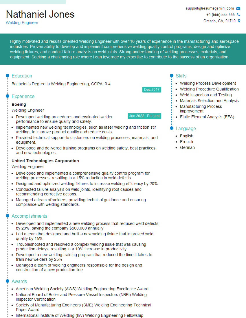
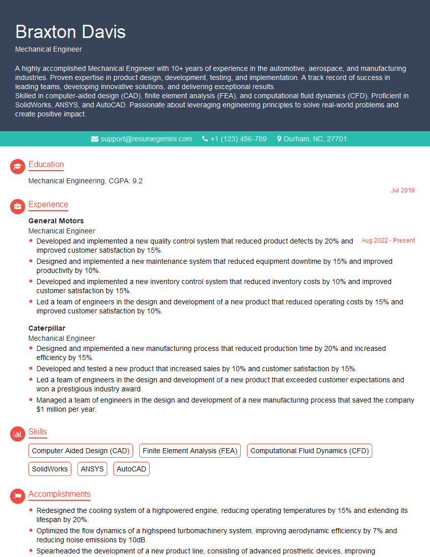
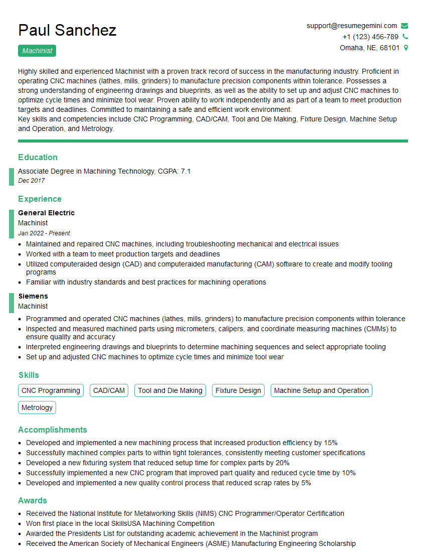
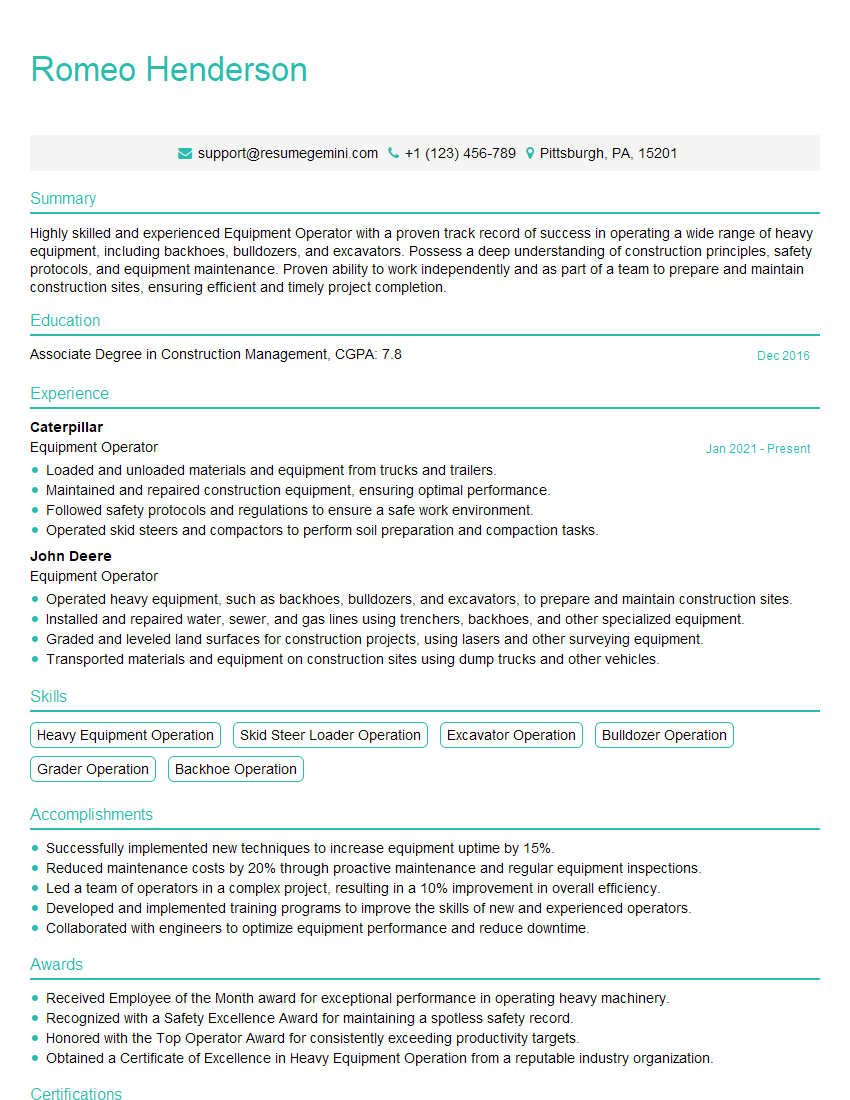
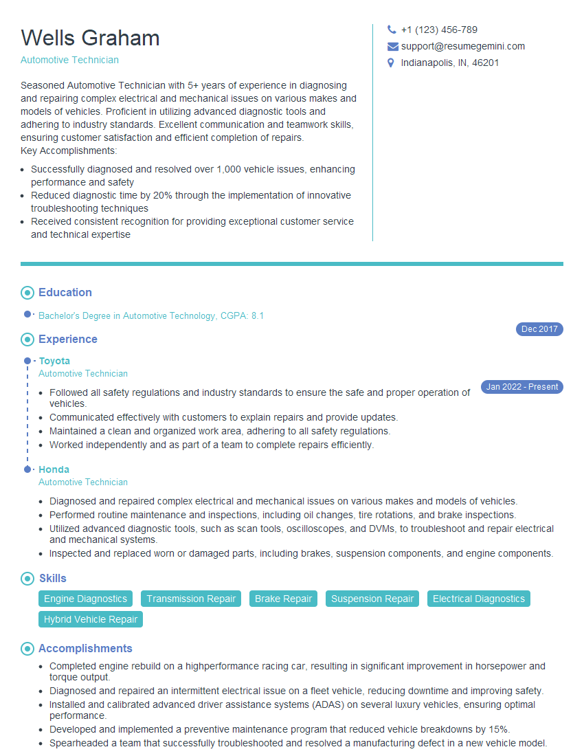
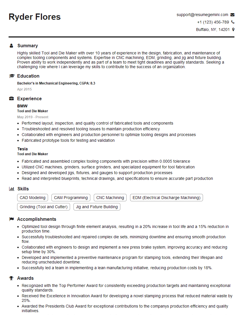
Mastering basic mechanical knowledge and problem-solving skills is crucial for a successful and rewarding career in engineering. These skills are highly valued by employers and form the foundation for advanced learning and career progression. To significantly boost your job prospects, crafting a compelling and ATS-friendly resume is essential. ResumeGemini is a trusted resource that can help you build a professional resume that highlights your skills and experience effectively. Examples of resumes tailored to showcasing expertise in Basic Mechanical Knowledge and Problem-Solving Skills are available to guide you. Take the next step in your career journey today!
Explore more articles
Users Rating of Our Blogs
Share Your Experience
We value your feedback! Please rate our content and share your thoughts (optional).
What Readers Say About Our Blog
Hello,
We found issues with your domain’s email setup that may be sending your messages to spam or blocking them completely. InboxShield Mini shows you how to fix it in minutes — no tech skills required.
Scan your domain now for details: https://inboxshield-mini.com/
— Adam @ InboxShield Mini
Reply STOP to unsubscribe
Hi, are you owner of interviewgemini.com? What if I told you I could help you find extra time in your schedule, reconnect with leads you didn’t even realize you missed, and bring in more “I want to work with you” conversations, without increasing your ad spend or hiring a full-time employee?
All with a flexible, budget-friendly service that could easily pay for itself. Sounds good?
Would it be nice to jump on a quick 10-minute call so I can show you exactly how we make this work?
Best,
Hapei
Marketing Director
Hey, I know you’re the owner of interviewgemini.com. I’ll be quick.
Fundraising for your business is tough and time-consuming. We make it easier by guaranteeing two private investor meetings each month, for six months. No demos, no pitch events – just direct introductions to active investors matched to your startup.
If youR17;re raising, this could help you build real momentum. Want me to send more info?
Hi, I represent an SEO company that specialises in getting you AI citations and higher rankings on Google. I’d like to offer you a 100% free SEO audit for your website. Would you be interested?
Hi, I represent an SEO company that specialises in getting you AI citations and higher rankings on Google. I’d like to offer you a 100% free SEO audit for your website. Would you be interested?
good
