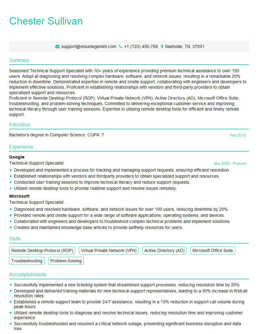
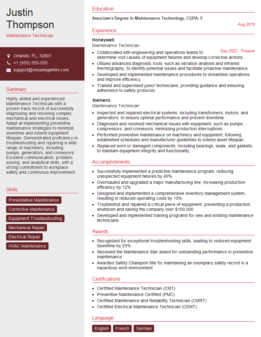
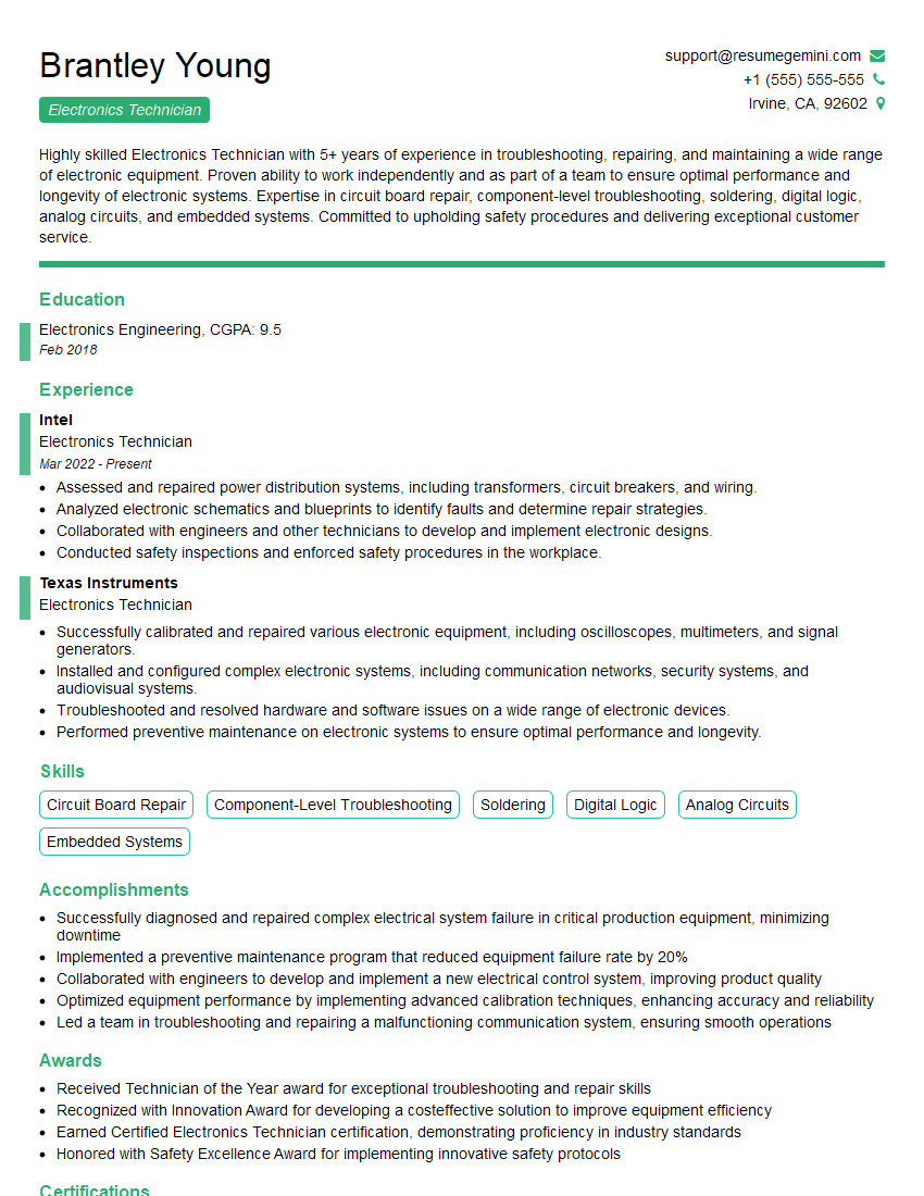
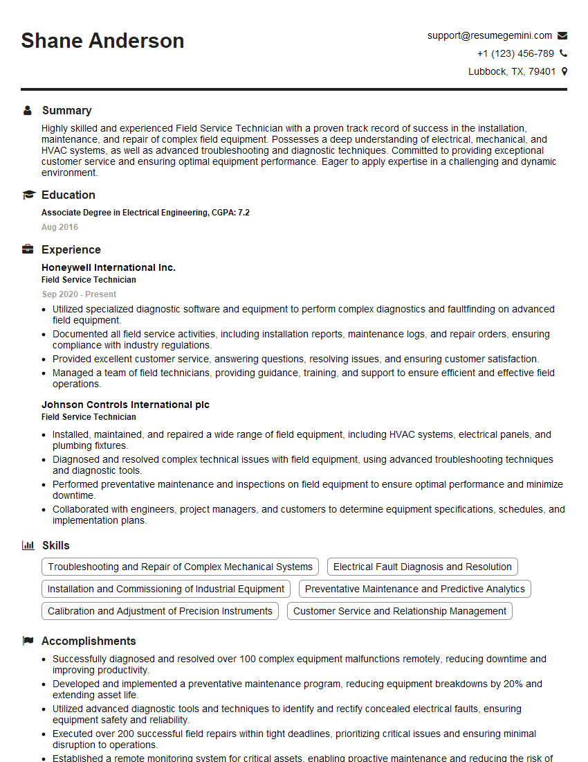
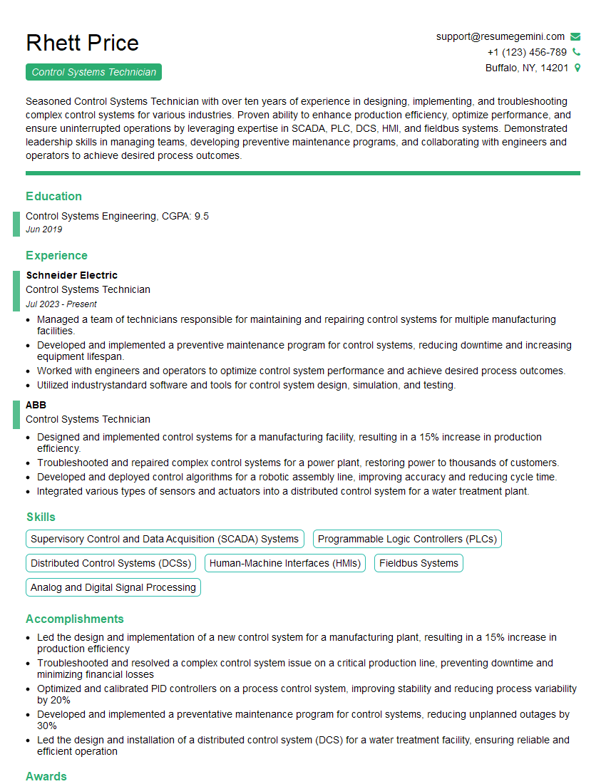
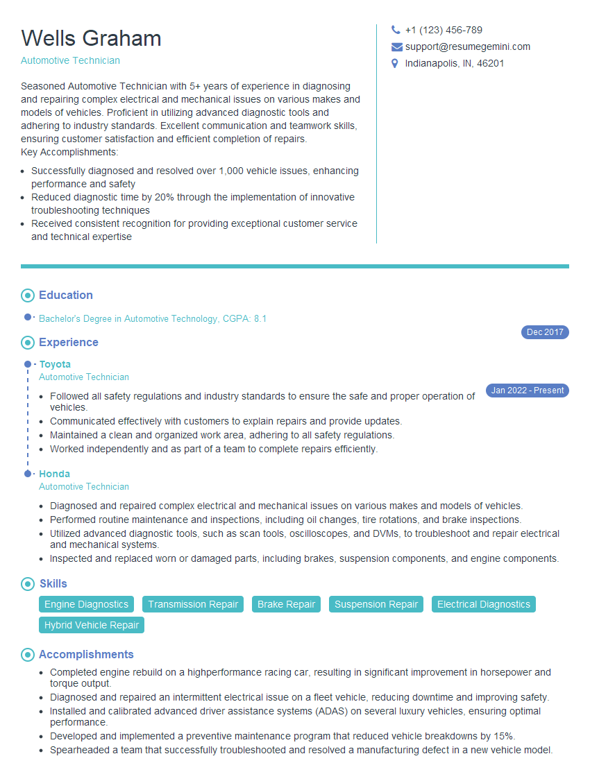
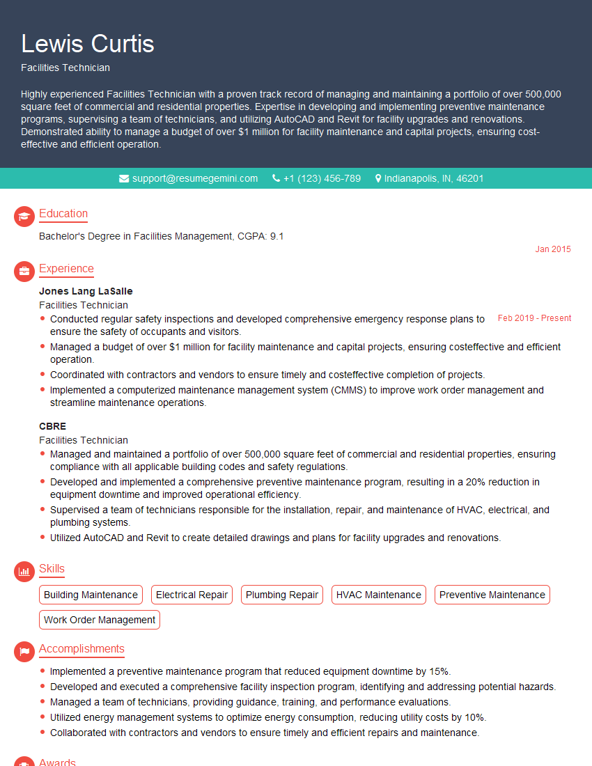
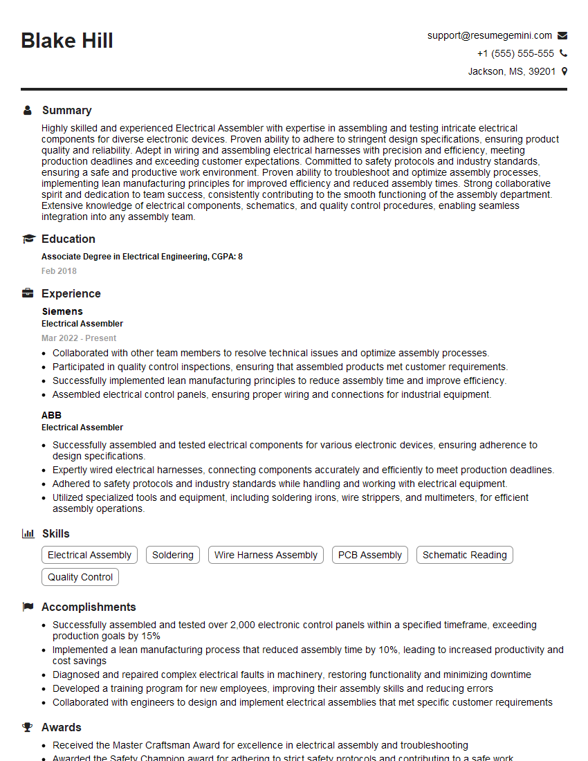
Unlock your full potential by mastering the most common Basic knowledge of electrical and mechanical principles interview questions. This blog offers a deep dive into the critical topics, ensuring you’re not only prepared to answer but to excel. With these insights, you’ll approach your interview with clarity and confidence.
Questions Asked in Basic knowledge of electrical and mechanical principles Interview
Q 1. Explain Ohm’s Law.
Ohm’s Law describes the relationship between voltage, current, and resistance in an electrical circuit. It states that the current flowing through a conductor is directly proportional to the voltage across it and inversely proportional to its resistance.
In simpler terms, if you increase the voltage, the current will increase, and if you increase the resistance, the current will decrease. This relationship is mathematically expressed as:
V = IRwhere:
Vrepresents voltage (measured in volts)Irepresents current (measured in amperes or amps)Rrepresents resistance (measured in ohms)
Imagine a water pipe analogy: Voltage is like the water pressure, current is the flow rate of water, and resistance is the pipe’s diameter (a narrower pipe offers more resistance). A higher pressure (voltage) will result in a faster flow (current) through a given pipe (resistance).
Ohm’s Law is fundamental in electrical engineering and is used for circuit analysis, troubleshooting, and design. For instance, if you know the voltage and resistance of a circuit, you can easily calculate the current flowing through it, or vice versa.
Q 2. What is the difference between AC and DC current?
The primary difference between AC (Alternating Current) and DC (Direct Current) lies in the direction of electron flow.
- DC current flows continuously in one direction. Think of a battery; it provides a constant flow of electrons from the positive terminal to the negative terminal. Examples include the power supply in your laptop or the current flowing in a simple circuit with a battery and a bulb.
- AC current periodically reverses its direction. The electrons oscillate back and forth. This is how electricity is supplied to our homes and businesses. The voltage and current change sinusoidally (in a wave-like pattern) over time. The frequency of this oscillation is typically 50 or 60 Hertz (Hz), depending on the region.
This difference impacts how electricity is used. DC is suitable for powering electronic devices that require a stable voltage, while AC is more efficient for long-distance transmission due to the ease of stepping up and down voltage levels using transformers.
Q 3. Describe the function of a capacitor.
A capacitor is a passive electronic component that stores electrical energy in an electric field. It essentially consists of two conductive plates separated by an insulating material called a dielectric.
When a voltage is applied across the capacitor, electrons accumulate on one plate, creating a negative charge, while the other plate develops a positive charge. This charge separation stores energy. The amount of charge a capacitor can store is proportional to its capacitance (measured in farads, F).
Capacitors are used in various applications, including:
- Filtering: Smoothing out variations in voltage or current.
- Energy storage: In power supplies or flash photography.
- Timing circuits: Creating specific time delays in electronic circuits.
- Coupling and decoupling: Transferring signals between different parts of a circuit or isolating noise.
Imagine a water tank: The tank stores water (energy), just as a capacitor stores electrical charge. The size of the tank (capacitance) determines how much water (charge) it can hold.
Q 4. What is the purpose of an inductor?
An inductor, also known as a coil or choke, is a passive electronic component that stores energy in a magnetic field. It typically consists of a wire wound into a coil, often around a core material that enhances its magnetic properties.
When current flows through the inductor, a magnetic field is generated. This magnetic field stores energy. If the current changes, the magnetic field also changes, inducing a voltage across the inductor that opposes this change in current (this is known as Lenz’s Law). The amount of energy an inductor can store is related to its inductance (measured in henries, H).
Inductors are used in a wide range of applications:
- Filtering: Blocking high-frequency signals while allowing low-frequency signals to pass through.
- Energy storage: In some power supplies.
- Tuning circuits: Used in radios and other frequency-selective circuits.
- Switching power supplies: Regulating voltage and current.
Think of a spring: When you compress or stretch it, it stores energy (similar to how an inductor stores energy in its magnetic field) and resists changes in its state.
Q 5. Explain the concept of voltage, current, and resistance.
Voltage, current, and resistance are fundamental concepts in electrical circuits.
- Voltage (V): Represents the electrical potential difference between two points in a circuit. It’s the ‘push’ or ‘pressure’ that drives the flow of electrons. Imagine it as the water pressure in a pipe – higher pressure means more forceful flow.
- Current (I): Represents the flow of electric charge (electrons) through a conductor. It’s the rate at which charge passes a given point in the circuit. In the water analogy, it’s the rate of water flow in the pipe.
- Resistance (R): Represents the opposition to the flow of current. It depends on the material’s properties, its dimensions, and temperature. In our water pipe analogy, resistance is akin to the pipe’s diameter – a narrower pipe offers more resistance to the water flow.
These three quantities are related by Ohm’s Law (V = IR), as described previously. Understanding these concepts is essential for analyzing and designing electrical circuits.
Q 6. What are the different types of motors?
There are many types of motors, categorized based on various factors like power source, construction, and operation principles. Some common types include:
- DC Motors: These motors run on direct current. Sub-types include brushed DC motors (using brushes for commutation) and brushless DC motors (using electronic commutation for higher efficiency and longer lifespan).
- AC Motors: These motors operate on alternating current. Key types are:
- Induction Motors: Widely used in industrial applications due to their robustness and relatively simple construction. These motors use a rotating magnetic field to induce current in the rotor, creating torque.
- Synchronous Motors: These motors run at a speed synchronized with the AC power frequency. They are used where precise speed control is needed, often requiring external excitation.
- Stepper Motors: Used for precise positioning and control. They rotate in discrete steps, making them ideal for robotics and automation.
- Servo Motors: These motors offer precise position, velocity, and torque control, often used in robotics, automation, and precision machinery.
- Linear Motors: These motors produce linear motion instead of rotational motion. Applications include high-speed transport systems and industrial automation.
The choice of motor depends on the specific application’s requirements, considering factors such as speed, torque, efficiency, cost, and size.
Q 7. Describe the function of a gearbox.
A gearbox is a mechanical device that changes the speed and torque of a rotating shaft. It consists of a set of gears arranged to achieve the desired speed and torque ratio.
Gearboxes are used to:
- Increase torque: A gearbox with a low gear ratio (output speed lower than input speed) increases torque. Think of a bicycle – lower gears provide more power for climbing hills.
- Increase speed: A gearbox with a high gear ratio (output speed higher than input speed) increases speed at the expense of torque. This is like shifting to a higher gear on a bicycle to achieve higher speed on a flat road.
- Change the direction of rotation: Gearboxes can reverse the direction of the output shaft.
Gearboxes are critical in various applications, including automobiles (transmission systems), industrial machinery, robotics, and wind turbines, to efficiently transfer power and match the speed and torque requirements of the driven equipment.
Q 8. Explain the principle of a lever.
A lever is a simple machine consisting of a rigid bar that pivots around a fixed point called a fulcrum. It’s based on the principle of moments – the tendency of a force to cause rotation around a pivot point. By applying a force (effort) to one end of the lever, we can move a load (resistance) at the other end. The lever’s effectiveness depends on the distances between the effort, load, and fulcrum.
Imagine using a crowbar to lift a heavy rock. The crowbar acts as the lever, the point where it rests on the ground is the fulcrum, the force you apply is the effort, and the rock is the resistance. The closer the fulcrum is to the load, the less effort you need to lift it; the farther the fulcrum is from the load (and closer to the effort), the more mechanical advantage you gain.
There are three classes of levers, categorized by the relative positions of the effort, load, and fulcrum: Class 1 (e.g., seesaw), Class 2 (e.g., wheelbarrow), and Class 3 (e.g., tweezers). Each class provides different mechanical advantages.
Q 9. What are the different types of bearings?
Bearings are mechanical components that reduce friction between moving parts. They allow for smooth rotation or linear motion. Several types exist, each suited for specific applications:
- Rolling-element bearings: These use rolling elements (balls or rollers) to separate moving surfaces. Examples include ball bearings (used widely in bicycles, motors) and roller bearings (often found in heavy machinery). They handle radial (perpendicular to the shaft) and sometimes axial (along the shaft) loads.
- Sliding bearings (or journal bearings): These use a lubricant (oil or grease) to minimize friction between two surfaces in relative motion. They are simpler than rolling-element bearings but generally have higher friction and are better suited for lower speeds and heavier loads. Examples include sleeve bearings found in engine blocks.
- Fluid film bearings: These use a fluid (usually oil) to separate the moving surfaces completely, resulting in extremely low friction. They are commonly used in high-speed applications and situations where minimal friction is critical.
- Thrust bearings: These are designed to handle primarily axial loads. They can be rolling-element or sliding types.
The choice of bearing depends on factors such as load capacity, speed, operating environment, and cost.
Q 10. How do hydraulic systems work?
Hydraulic systems use pressurized liquid (usually oil) to transmit power. They work on Pascal’s principle, which states that pressure applied to a confined fluid is transmitted equally and undiminished to all points in the fluid and to the walls of the container.
A typical hydraulic system includes a pump to pressurize the fluid, valves to control the flow direction and pressure, actuators (cylinders) to convert hydraulic pressure into mechanical force, and a reservoir to store the fluid. When the pump increases the pressure in the system, this pressure is transmitted throughout the fluid, forcing the actuators to move. The force generated by the actuator is proportional to the pressure and the area of the cylinder.
Think of a hydraulic jack used to lift cars. A small force applied to a small piston generates a high pressure in the hydraulic fluid, which is transmitted to a larger piston, creating a much larger force to lift the car. This is an example of hydraulic multiplication.
Q 11. How do pneumatic systems work?
Pneumatic systems use compressed air or gas to transmit power. Similar to hydraulic systems, they utilize the principle of pressure transmission. However, air is compressible, leading to differences in how they operate.
A typical pneumatic system includes an air compressor to compress the air, air tanks to store the compressed air, valves to control the flow and pressure, and actuators (pneumatic cylinders) to convert air pressure into mechanical work. Air pressure controls the speed and force of the actuators. Because air is compressible, pneumatic systems can be more forgiving in case of overloads, as the air cushions the impact.
Examples of pneumatic systems include air brakes in vehicles and automated systems in factories. The use of air makes them safer in some applications as the energy density is lower than with hydraulic systems.
Q 12. What are the safety precautions when working with electricity?
Safety precautions when working with electricity are paramount. Never work on live electrical systems unless properly trained and equipped. Always:
- Lockout/Tagout: Before working on any electrical equipment, always lockout and tagout the power supply to prevent accidental energization.
- Use proper PPE: Wear appropriate personal protective equipment (PPE), including insulated gloves, safety glasses, and non-conductive footwear.
- Inspect equipment: Carefully inspect tools and equipment for any damage before use.
- Ground yourself: When working with electricity, ensure you’re properly grounded to prevent electrical shocks.
- Understand circuit diagrams: Thoroughly understand the electrical circuit before working on it.
- Use appropriate tools: Use only tools designed for electrical work.
- Never work alone: Always have a second person present when working with electricity, preferably someone who can assist in an emergency.
Ignoring these precautions can lead to serious injury or death.
Q 13. What are the safety precautions when working with machinery?
Safety when working with machinery requires diligence and adherence to specific procedures. Key precautions include:
- Guardrails and safety devices: Ensure all safety guards, interlocks, and emergency stops are in place and functioning correctly before operating machinery.
- Proper training: Only operate machinery after receiving adequate training and authorization.
- PPE: Wear appropriate personal protective equipment, including safety glasses, hearing protection, gloves, and steel-toed boots, as necessary.
- Lockout/Tagout: Before performing maintenance or repairs, always lockout and tagout the power source to prevent accidental starting.
- Clear work area: Maintain a clean and organized work area free from obstructions.
- Follow operating procedures: Always adhere to the manufacturer’s operating instructions and safety guidelines.
- Report hazards: Report any unsafe conditions or malfunctions immediately.
Failure to follow these precautions can lead to severe injuries or fatalities.
Q 14. Explain the concept of torque.
Torque is a measure of the rotational force applied to an object. It’s the tendency of a force to cause rotation around an axis. It’s calculated as the product of the force and the perpendicular distance from the axis of rotation to the point where the force is applied.
The formula for torque (τ) is: τ = r × F, where ‘r’ is the distance (lever arm) and ‘F’ is the force. The units of torque are Newton-meters (Nm).
Imagine tightening a bolt with a wrench. The force you apply to the wrench handle is the force (F), and the distance from the bolt to your hand is the lever arm (r). The greater the force or the longer the wrench handle, the greater the torque you apply, resulting in a tighter bolt.
Torque is crucial in many applications, including engine design (engine torque determines how quickly it can accelerate), fastening systems, and robotics (controlling the rotation of robotic arms).
Q 15. Explain the concept of horsepower.
Horsepower (hp) is a unit of measurement of power, representing the rate at which work is done. It’s a legacy unit, originally defined as the power a horse could produce. While not an SI unit (the International System of Units prefers watts), it’s still commonly used, particularly in the automotive and mechanical industries. One horsepower is approximately equal to 746 watts.
Imagine lifting a heavy weight. The faster you lift it, the more power you’re using. Horsepower quantifies this power. A more powerful engine, for example, can accelerate a vehicle faster because it can deliver more horsepower. It’s crucial for engineers to calculate the horsepower requirements for various applications to ensure sufficient power is available for the intended task.
Example: A car’s engine might be rated at 200 horsepower, meaning it can do work at a rate equivalent to 200 horses working simultaneously. This power is used to overcome friction, acceleration, and other forces resisting the car’s movement.
Career Expert Tips:
- Ace those interviews! Prepare effectively by reviewing the Top 50 Most Common Interview Questions on ResumeGemini.
- Navigate your job search with confidence! Explore a wide range of Career Tips on ResumeGemini. Learn about common challenges and recommendations to overcome them.
- Craft the perfect resume! Master the Art of Resume Writing with ResumeGemini’s guide. Showcase your unique qualifications and achievements effectively.
- Don’t miss out on holiday savings! Build your dream resume with ResumeGemini’s ATS optimized templates.
Q 16. What are the different types of gears?
Gears are toothed wheels used to transmit rotational motion and torque between shafts. Different types of gears are designed for specific applications based on factors like speed ratio, torque transmission, and space constraints.
- Spur Gears: These are the simplest type, with straight teeth parallel to the axis of rotation. They’re efficient for parallel shafts but can be noisy at high speeds.
- Helical Gears: Their teeth are inclined to the axis, providing smoother and quieter operation than spur gears, and higher load-carrying capacity. However, they introduce axial thrust.
- Bevel Gears: Used to transmit power between intersecting shafts. They can be straight-bevel or spiral-bevel, with spiral bevel gears offering smoother operation.
- Worm Gears: A worm gear consists of a worm (screw-like gear) and a worm wheel. They provide high gear ratios in a compact space, are self-locking (meaning the output shaft won’t rotate if the input shaft is stationary), but can be less efficient.
- Rack and Pinion Gears: Convert rotational motion into linear motion. The rack is a linear gear, and the pinion is a rotating gear. Commonly used in steering mechanisms.
Choosing the right type of gear is crucial for optimal performance and efficiency in a mechanical system. Consider factors like speed, torque, noise levels, and space limitations when selecting the appropriate gear type.
Q 17. Describe the function of a pulley system.
A pulley system uses one or more wheels (pulleys) and a rope, cable, or belt to lift or move heavy objects. The system’s mechanical advantage allows you to lift heavier weights with less effort. The mechanical advantage is the ratio of the output force (the weight lifted) to the input force (the force applied).
Consider a simple pulley system with one fixed pulley and one movable pulley. In this case, the mechanical advantage is 2. This means you only need to pull with half the weight’s force to lift it. The tradeoff is that you need to pull the rope twice the distance the weight is lifted.
Pulley systems are used extensively in construction (cranes, hoists), manufacturing (material handling), and even in simple tasks like raising flags. The number of pulleys and their arrangement determine the mechanical advantage and efficiency of the system.
Q 18. What is a circuit breaker and how does it work?
A circuit breaker is an electrical safety device designed to protect an electrical circuit from damage caused by overcurrent/overload or short circuits. Unlike fuses, which are one-time use devices, circuit breakers can be reset after tripping.
They work by detecting excessive current flow. When the current exceeds a predetermined threshold, an internal mechanism trips, breaking the circuit and interrupting the flow of electricity. This prevents overheating and potential fires. The mechanism usually involves an electromagnet or a bimetallic strip that responds to heat generated by excessive current. Once the fault is cleared, the circuit breaker can be manually reset, restoring power.
Example: In your home, circuit breakers protect individual circuits (lighting, outlets, etc.). If a short circuit occurs in a lamp, the circuit breaker for that circuit will trip, preventing damage to the wiring and protecting your house from a fire.
Q 19. What is a fuse and how does it work?
A fuse is a safety device containing a thin wire or metal strip that melts and breaks the circuit when excessive current flows through it. This prevents damage to electrical equipment and prevents fire hazards.
The fuse’s thin wire has a low melting point. When the current exceeds the fuse’s rated capacity, the wire melts, creating an open circuit and stopping the current flow. Fuses are ‘one-shot’ devices – once they blow, they must be replaced.
Example: Many older homes use fuses instead of circuit breakers. If a surge of current occurs, the fuse will blow, requiring replacement with a new fuse of the same rating. Fuses are often used in smaller appliances or as secondary protection.
Q 20. Explain the concept of power factor.
Power factor (PF) is a measure of how efficiently electrical power is used in an AC (alternating current) circuit. It’s the ratio of the real power (kW) used by a load to the apparent power (kVA) supplied to the load. The power factor ranges from 0 to 1.
A power factor of 1 indicates perfect efficiency – all the supplied power is used as real power to do useful work. A power factor less than 1 indicates that some of the power is reactive power, which doesn’t do any useful work but still stresses the electrical system. Reactive power is associated with inductive or capacitive loads (like motors and capacitors).
Low power factor increases electricity costs and can lead to inefficient operation of electrical equipment. Power factor correction techniques (using capacitors) are often employed to improve the power factor closer to 1.
Example: An inductive load like a motor might have a power factor of 0.8. This means only 80% of the apparent power is actually used for work; the remaining 20% is reactive power.
Q 21. What is the difference between a relay and a contactor?
Both relays and contactors are electromechanical switches used to control electrical circuits, but they differ in their applications and capabilities.
- Relay: A relay uses a small amount of current to control a larger current. It’s typically used for low-power switching applications, such as controlling signals or smaller loads. Relays are often found in control systems, automation, and electronics.
- Contactor: A contactor is a heavy-duty switch designed to handle high currents and voltages. They’re used for controlling large loads like motors, heaters, and lighting systems. Contactors are commonly used in industrial applications and power distribution.
In essence, a relay is a smaller, lower-power switch, while a contactor is built for higher power and heavier loads. Think of a relay like the switch that turns on your car’s headlights (low current controlling higher current) and a contactor like the switch that controls the powerful motor of a crane (high current switching).
Q 22. How do you troubleshoot a simple electrical circuit?
Troubleshooting a simple electrical circuit involves systematically identifying the fault causing malfunction. Think of it like detective work – you need to gather clues and eliminate possibilities.
- Visual Inspection: Begin by carefully examining all components for any obvious damage like loose wires, burnt resistors, or broken connections. This is often the easiest way to spot the problem.
- Check Power Source: Ensure the power source (battery or outlet) is functioning correctly. A simple multimeter can confirm voltage is present.
- Use a Multimeter: A multimeter is your best friend. Use it to check voltage at various points in the circuit. If voltage is present before a component but absent after, the component is likely faulty.
- Continuity Test: Use the multimeter’s continuity test to check for breaks in wires or circuits. A continuous tone indicates a closed path, while no tone suggests a break.
- Systematic Approach: If the problem isn’t immediately obvious, start by isolating sections of the circuit. Disconnect components one by one until you identify the faulty part. For example, if you have a circuit with a light bulb and a switch, disconnect the bulb and check if the switch is working correctly. Then, reconnect the bulb and see if the switch correctly controls it.
Example: Imagine a simple circuit with a battery, a switch, and a light bulb. If the light doesn’t turn on, you’d first check the battery voltage, then the switch’s continuity, and finally, the bulb’s filament for a break.
Q 23. How do you troubleshoot a simple mechanical system?
Troubleshooting a mechanical system relies on understanding how the system works and systematically eliminating potential causes of failure. It’s like fixing a bicycle – you need to pinpoint what part isn’t working properly.
- Identify the Problem: Begin by precisely defining what is wrong. Is it making noise? Is it not moving? Is it moving too slowly?
- Visual Inspection: Look for obvious problems like broken parts, loose connections, or obstructions.
- Check for Wear and Tear: Look for signs of excessive wear, rust, or damage to moving parts. This is particularly crucial in systems with gears, bearings, or belts.
- Listen for Unusual Sounds: Grinding, squealing, or knocking sounds often indicate problems with bearings, gears, or other moving parts.
- Check Lubrication: Insufficient lubrication can cause friction and damage. Check lubrication points and add lubricant if needed.
- Test Individual Components: If possible, isolate and test individual components to determine which one is faulty.
Example: If a simple gear system isn’t turning smoothly, you might first check for obstructions, then inspect the gears for wear, and finally examine the bearings for lubrication and damage.
Q 24. Describe different types of welding.
Welding is a fabrication process that joins materials, usually metals or thermoplastics, by causing coalescence. Different welding types use various methods to achieve this:
- Shielded Metal Arc Welding (SMAW): Also known as stick welding, this method uses a consumable electrode coated with flux to protect the weld from atmospheric contamination.
- Gas Metal Arc Welding (GMAW): Often called MIG (Metal Inert Gas) welding, this process uses a continuous solid wire electrode fed through a welding gun. A shielding gas, typically argon or a mix of argon and CO2, protects the weld pool.
- Gas Tungsten Arc Welding (GTAW): Also known as TIG (Tungsten Inert Gas) welding, this process employs a non-consumable tungsten electrode and an inert shielding gas. It is known for high-quality welds but requires more skill.
- Resistance Welding: This method uses electrical resistance to heat and join the materials. Spot welding, seam welding, and projection welding are common types of resistance welding.
- Oxy-fuel Welding: This older technique uses a flame produced by burning oxygen and fuel gas (acetylene) to melt the base metals and a filler material.
Each method is suitable for different materials and applications. The choice depends on factors such as material thickness, joint type, and desired weld quality.
Q 25. Explain basic troubleshooting techniques for motors.
Troubleshooting motors involves systematically checking various components and parameters to isolate the cause of malfunction. The approach is similar to detective work, aiming to find the cause of the problem.
- Visual Inspection: Begin by inspecting the motor for any obvious physical damage, such as loose connections, burnt windings, or mechanical damage.
- Check Power Supply: Ensure the motor is receiving the correct voltage and amperage. A multimeter is essential here.
- Test for Continuity: Use a multimeter to check the continuity of the motor windings. An open circuit indicates a broken winding.
- Check for Insulation Resistance: Measure the insulation resistance of the windings using a megohmmeter. Low resistance may indicate winding insulation failure.
- Listen for Unusual Sounds: Unusual noises like grinding, humming, or knocking can indicate bearing wear or other mechanical problems.
- Check Bearings and Mechanical Components: Inspect bearings for wear or damage. Check for any binding or obstructions in the mechanical system connected to the motor.
- Check Load: A motor may struggle if the connected load is too high. Try reducing the load to see if this improves performance.
Example: If a motor fails to start, you might first check the power supply, then the windings for continuity and insulation resistance, and finally, examine the bearings for wear.
Q 26. What is a schematic diagram and how is it used?
A schematic diagram is a simplified graphical representation of a circuit or system. It uses standard symbols to represent components and their interconnections. Think of it as a map showing how the electrical or mechanical parts are connected.
Uses:
- Design and Planning: Schematics are crucial during the design phase to plan the layout and connections of a circuit or system.
- Troubleshooting: They are invaluable for troubleshooting problems. By following the paths on the schematic, you can trace signals and identify potential points of failure.
- Documentation: Schematics serve as essential documentation for maintaining and repairing a system.
- Communication: They facilitate communication among engineers, technicians, and other stakeholders.
Example: A schematic of a simple circuit might show a battery symbol connected to a switch symbol, which is then connected to a light bulb symbol. This clearly illustrates the connection path of the power flow.
Q 27. Explain the concept of mechanical advantage.
Mechanical advantage is a measure of the force amplification achieved by a mechanical system. It’s essentially the ratio of the output force to the input force. It makes tasks easier by reducing the effort needed to accomplish work.
Concept: A simple machine, like a lever or pulley, can increase the force you apply. The mechanical advantage quantifies this increase. A mechanical advantage greater than 1 means the output force is larger than the input force.
Formula: Mechanical Advantage = Output Force / Input Force
Example: A lever used to lift a heavy rock provides mechanical advantage. By applying a smaller force to the lever’s longer arm, you can lift a much heavier rock on the shorter arm.
Q 28. Describe the difference between series and parallel circuits.
Series and parallel circuits are two fundamental ways to connect components in an electrical system. They differ significantly in how they handle current and voltage.
- Series Circuit: In a series circuit, components are connected end-to-end, forming a single path for current to flow. The current is the same through all components, but the voltage is divided among them. If one component fails, the entire circuit breaks.
- Parallel Circuit: In a parallel circuit, components are connected across each other, providing multiple paths for current to flow. The voltage is the same across all components, but the current is divided among them. If one component fails, the others continue to function.
Analogy: Imagine a series of pipes connected end-to-end (series) versus pipes connected side-by-side (parallel). In the series setup, if one pipe breaks, water flow stops. In the parallel setup, water can still flow even if one pipe is blocked.
Example: Christmas lights often used to be wired in series; if one bulb failed, the entire string went dark. Modern strings are often wired in parallel, so a single bulb’s failure won’t affect the rest.
Key Topics to Learn for Basic Electrical and Mechanical Principles Interview
- Electrical Fundamentals: Understanding basic circuit concepts (Ohm’s Law, Kirchhoff’s Laws), voltage, current, resistance, power, and energy. Explore different types of circuits (series, parallel) and their applications.
- Mechanical Fundamentals: Grasping core concepts like forces, motion, energy (potential and kinetic), work, and power. Familiarize yourself with simple machines (levers, pulleys, gears) and their mechanical advantage.
- Electrical Components: Become comfortable identifying and understanding the function of common electrical components such as resistors, capacitors, inductors, diodes, and transistors. Consider their role in various circuits.
- Mechanical Systems: Learn about different types of mechanical systems, including simple machines, linkages, and power transmission systems. Understand concepts like torque, rotation, and friction.
- Practical Applications: Relate theoretical concepts to real-world applications. For example, how Ohm’s Law applies to household circuits, or how levers are used in various mechanical systems.
- Problem-Solving: Develop your ability to analyze simple electrical and mechanical problems, using diagrams and calculations to arrive at solutions. Practice applying learned concepts to solve practical scenarios.
- Troubleshooting: Familiarize yourself with basic troubleshooting techniques for simple electrical and mechanical systems. This might involve identifying faulty components or understanding the cause of malfunctions.
- Safety Procedures: Understand basic safety precautions when working with electricity and machinery. This is crucial for any role involving these principles.
Next Steps
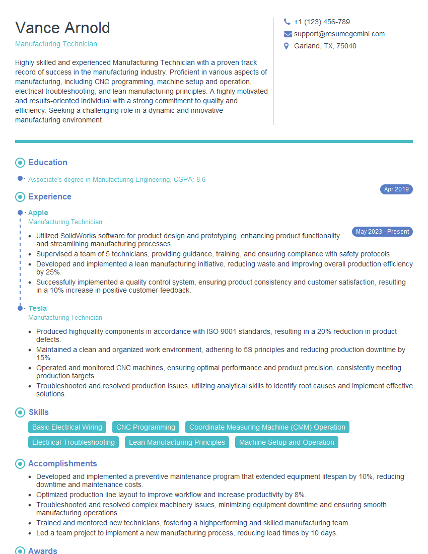
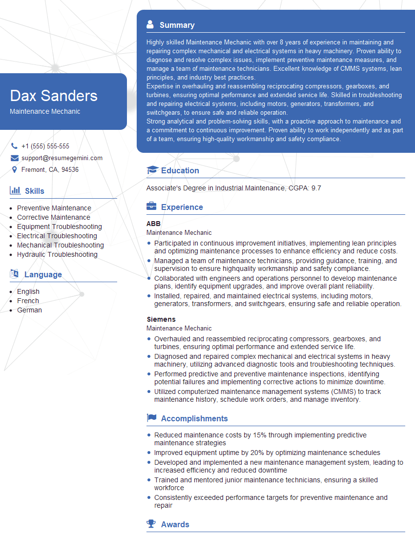
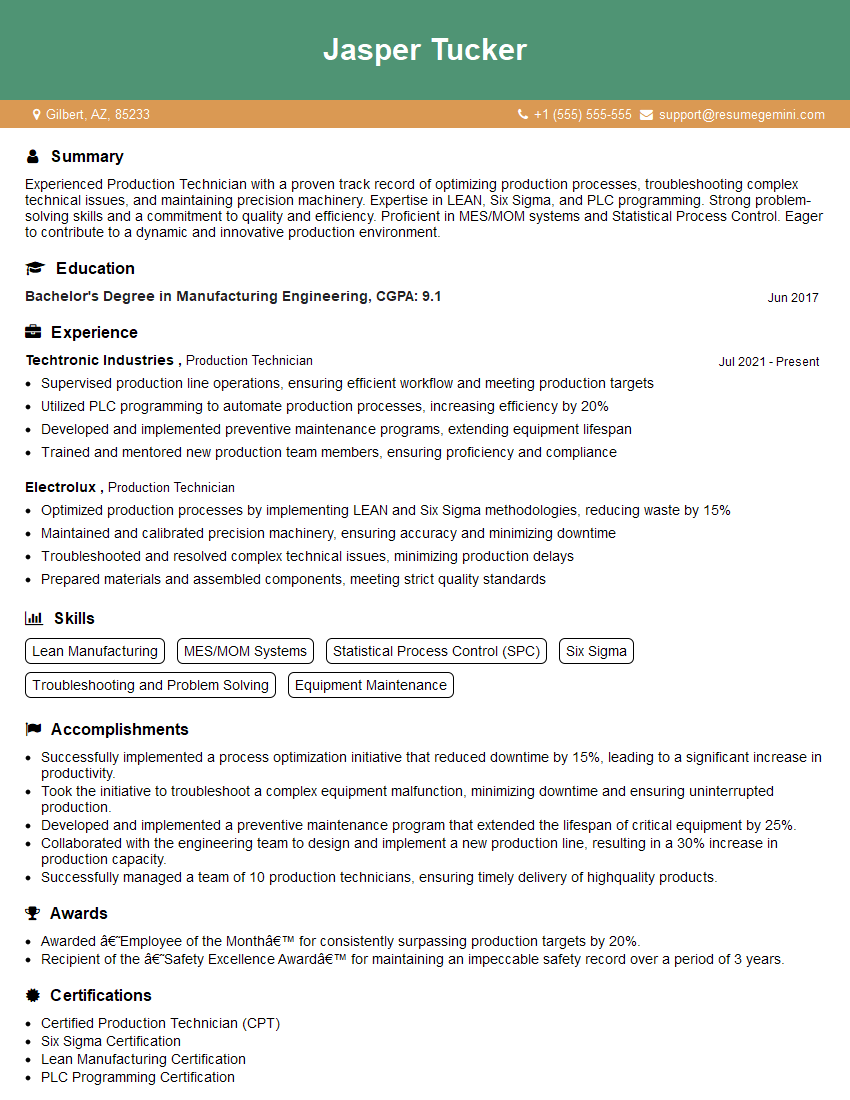
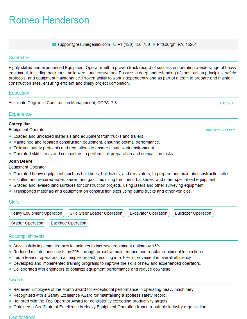
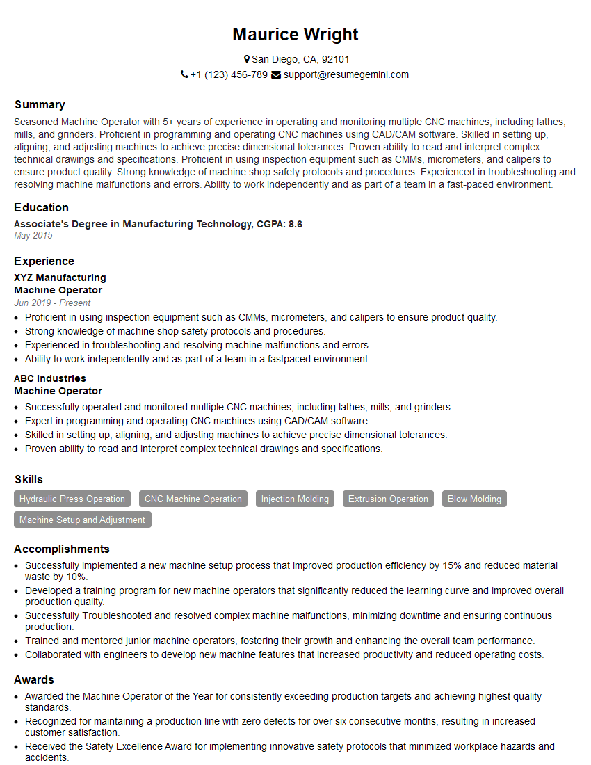
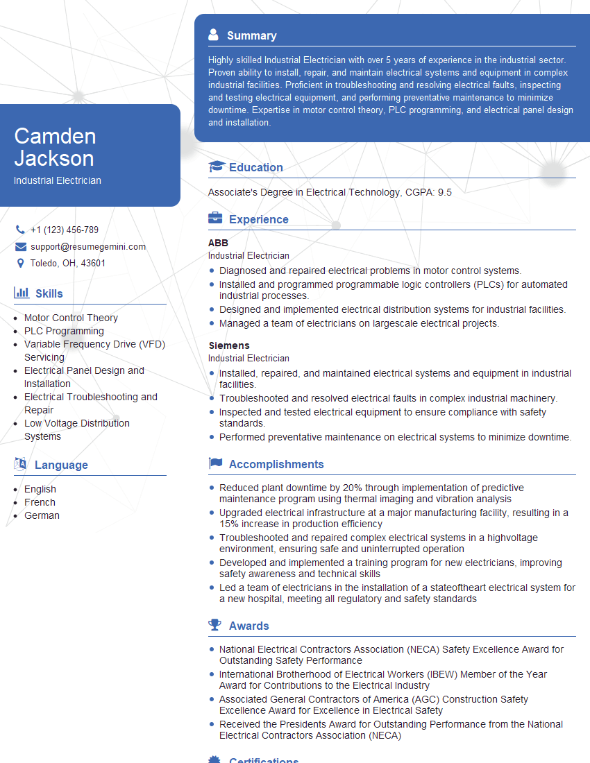
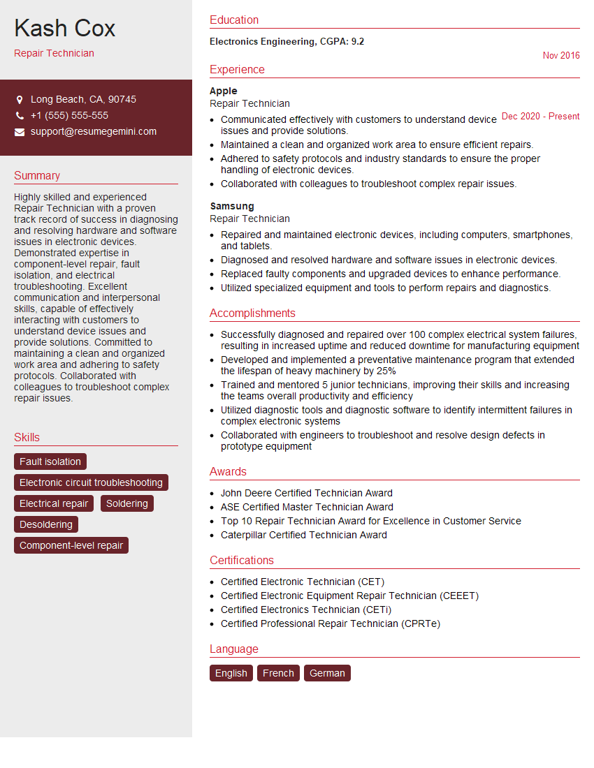
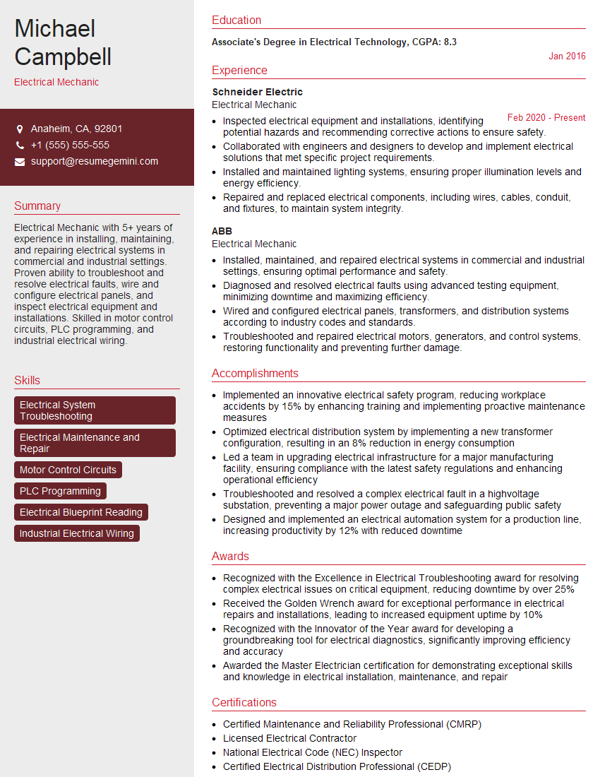
Mastering basic electrical and mechanical principles is vital for career advancement in numerous technical fields. A strong understanding of these fundamentals demonstrates a solid foundation and problem-solving aptitude, making you a more competitive candidate. To further enhance your job prospects, it’s crucial to create an ATS-friendly resume that effectively highlights your skills and experience. ResumeGemini is a trusted resource to help you build a professional and impactful resume that gets noticed. We provide examples of resumes tailored to roles requiring a basic knowledge of electrical and mechanical principles, helping you present your qualifications in the best possible light.
Explore more articles
Users Rating of Our Blogs
Share Your Experience
We value your feedback! Please rate our content and share your thoughts (optional).
What Readers Say About Our Blog
Hello,
We found issues with your domain’s email setup that may be sending your messages to spam or blocking them completely. InboxShield Mini shows you how to fix it in minutes — no tech skills required.
Scan your domain now for details: https://inboxshield-mini.com/
— Adam @ InboxShield Mini
Reply STOP to unsubscribe
Hi, are you owner of interviewgemini.com? What if I told you I could help you find extra time in your schedule, reconnect with leads you didn’t even realize you missed, and bring in more “I want to work with you” conversations, without increasing your ad spend or hiring a full-time employee?
All with a flexible, budget-friendly service that could easily pay for itself. Sounds good?
Would it be nice to jump on a quick 10-minute call so I can show you exactly how we make this work?
Best,
Hapei
Marketing Director
Hey, I know you’re the owner of interviewgemini.com. I’ll be quick.
Fundraising for your business is tough and time-consuming. We make it easier by guaranteeing two private investor meetings each month, for six months. No demos, no pitch events – just direct introductions to active investors matched to your startup.
If youR17;re raising, this could help you build real momentum. Want me to send more info?
Hi, I represent an SEO company that specialises in getting you AI citations and higher rankings on Google. I’d like to offer you a 100% free SEO audit for your website. Would you be interested?
Hi, I represent an SEO company that specialises in getting you AI citations and higher rankings on Google. I’d like to offer you a 100% free SEO audit for your website. Would you be interested?
good
