Every successful interview starts with knowing what to expect. In this blog, we’ll take you through the top Drawing in interview questions, breaking them down with expert tips to help you deliver impactful answers. Step into your next interview fully prepared and ready to succeed.
Questions Asked in Drawing in Interview
Q 1. Explain your experience with various CAD software (AutoCAD, Revit, SolidWorks, etc.).
My experience with CAD software spans several platforms, each suited to different tasks. AutoCAD remains my go-to for 2D drafting, particularly for its robust capabilities in creating precise plans and detailed drawings for construction projects. I’ve used it extensively for site plans, floor plans, and detailed construction drawings, leveraging its powerful annotation tools and layer management for complex designs. Revit, on the other hand, is my preferred choice for Building Information Modeling (BIM). Its parametric modeling capabilities allow for dynamic changes and real-time collaboration, making it ideal for large-scale projects requiring coordination among multiple disciplines. For example, I used Revit to model a multi-story office building, effectively managing clashes and optimizing the design. Finally, I’ve utilized SolidWorks for 3D modeling, primarily for mechanical components and assemblies. Its intuitive interface and powerful simulation tools were crucial for a project designing a custom fixture where I needed to ensure structural integrity under stress.
Q 2. Describe your proficiency in 2D and 3D drafting.
My proficiency in both 2D and 3D drafting is extensive. In 2D, I’m highly skilled in creating precise technical drawings using various CAD software, ensuring compliance with industry standards like ANSI and ISO. I’m comfortable generating detailed orthographic projections, sections, and details required for manufacturing or construction. For example, I’ve created detailed shop drawings for custom metal fabrication projects, clearly illustrating dimensions, tolerances, and material specifications. My 3D drafting skills involve creating realistic models using SolidWorks and Revit, focusing on accuracy and detail. This allows for thorough visualization of projects, assisting in design review and problem-solving. I’ve used 3D modeling to identify and resolve potential clashes in a complex HVAC system design before construction began, saving significant time and cost.
Q 3. How do you handle revisions and updates to existing drawings?
Handling revisions and updates is a critical part of the drafting process. I use a systematic approach, typically starting with clearly identifying the revision and its source. Then, using version control within the CAD software (e.g., revision clouds in AutoCAD or Revit’s version history), I make the necessary changes, meticulously documenting each alteration. This ensures traceability and allows for easy backtracking if needed. I also maintain a revision log, detailing the date, author, and description of each modification. Clear communication with stakeholders is crucial during this phase to ensure everyone is aware of the updates and their implications. For example, in a recent project, we made several revisions to a floor plan based on client feedback. Each revision was meticulously documented, allowing for seamless communication and a final product that met the client’s expectations.
Q 4. What are your preferred methods for creating detailed technical drawings?
My preferred methods for creating detailed technical drawings involve a multi-step process. First, I thoroughly understand the project requirements and specifications. This includes careful review of client briefs, site surveys, and relevant standards. Then, I develop a comprehensive plan outlining the drawing scope and the sequence of steps involved. I then utilize appropriate CAD software to create the model or drawing, focusing on accuracy and clarity. This includes precisely defining dimensions, tolerances, and material specifications. Finally, I conduct thorough quality checks, reviewing the drawing for completeness, consistency, and adherence to standards before finalizing and releasing it. For example, when creating detailed drawings for a custom staircase, I ensured all dimensions were precisely calculated and clearly indicated, with specific details on the material, finish, and connections to adjacent components.
Q 5. Explain your understanding of different drawing standards (ANSI, ISO, etc.).
I have a strong understanding of various drawing standards, including ANSI (American National Standards Institute) and ISO (International Organization for Standardization). ANSI standards are prevalent in the United States, while ISO standards are internationally recognized. These standards provide guidelines for dimensions, tolerances, sheet sizes, and other critical aspects of technical drawing. Understanding these standards ensures consistency and clarity in communication across various projects and geographical locations. For example, I’ve consistently used ANSI standards for construction drawings in US-based projects and ISO standards for international projects, understanding the subtle differences in notation and requirements for each. This ensures that my drawings are easily understood by the intended audience.
Q 6. How do you ensure accuracy and precision in your drawings?
Ensuring accuracy and precision is paramount in my work. I employ various techniques to achieve this. Firstly, I use appropriate measuring tools and techniques during the initial data collection phase, double-checking all measurements. Within the CAD software, I leverage tools like constraints and parametric modeling to maintain dimensional relationships and prevent errors from propagating. I regularly cross-check dimensions and coordinate values to identify potential discrepancies. Furthermore, I employ rigorous quality control checks before finalizing any drawing. This might include peer reviews or utilizing built-in CAD software tools to detect inconsistencies. I also meticulously maintain a version history to track changes and ensure revisions are accurately reflected. For instance, during the design of a complex mechanical assembly, using constraints in SolidWorks prevented inaccuracies and ensured all parts fitted perfectly.
Q 7. Describe your experience with creating and managing drawing files.
My experience in creating and managing drawing files involves utilizing a well-organized file management system. I use a hierarchical folder structure to organize projects, ensuring easy retrieval of specific drawings. I always maintain backups of project files, using cloud storage and local backups to prevent data loss. I name files systematically, including project ID, drawing number, and revision number for easy identification. When collaborating on a project, I utilize cloud-based platforms that support version control and facilitate collaboration among team members, ensuring that everyone is working with the latest version of the drawings. This organized approach minimizes the risk of errors and ensures seamless collaboration on large-scale projects.
Q 8. How do you collaborate with other team members on drawing projects?
Collaboration on drawing projects hinges on effective communication and a shared understanding of the project goals. I typically utilize a combination of methods, depending on project size and team structure. For smaller projects, we might use a shared cloud-based drawing platform like Dropbox or Google Drive, allowing for real-time feedback and version control. This is especially useful for quick iterations and design revisions. Larger, more complex projects often benefit from a structured approach, using project management software such as Autodesk BIM 360 or similar platforms. These tools provide central repositories for drawings, documentation, and communication channels, facilitating clear task assignments and progress tracking. Regardless of the platform, regular team meetings – both in person and virtual – are crucial for addressing challenges, brainstorming solutions, and ensuring everyone is aligned.
For instance, on a recent commercial building project, we used BIM 360. Each team member (architects, structural engineers, MEP engineers) had access to their designated sections of the model, and we held weekly progress meetings to discuss potential conflicts and coordinate our work. This collaborative process significantly reduced errors and ensured timely project completion.
Q 9. Explain your process for troubleshooting drawing errors.
Troubleshooting drawing errors is a systematic process. My first step always involves carefully reviewing the drawing itself, checking for inconsistencies in dimensions, notations, or geometry. This often reveals obvious mistakes. If not, I move onto a more detailed analysis, comparing the drawing against the design specifications, contract documents, and relevant codes. Identifying the source of the error is crucial; is it a misunderstanding of the requirements, a software glitch, or an oversight in the drafting process?
For example, if dimensions don’t add up, I might check for scaling issues or missing segments. If there are conflicts with structural elements, I’ll consult with the structural engineer. Software glitches can be tricky but often require a close examination of the drawing file and potentially reverting to an earlier version. I meticulously document all troubleshooting steps, including the error, the analysis undertaken, and the implemented solution. This allows for improved efficiency in future projects and helps prevent similar mistakes from occurring.
Q 10. Describe your experience with creating construction drawings.
I possess extensive experience creating construction drawings, ranging from residential to large-scale commercial projects. My expertise spans various drawing types, including floor plans, elevations, sections, details, and schedules. I’m proficient in using industry-standard software like AutoCAD and Revit, and I understand the importance of adhering to industry best practices and relevant building codes. Creating construction drawings is more than just drafting; it requires a thorough understanding of construction techniques, material specifications, and building regulations to ensure clarity and accuracy for contractors and builders.
For example, in one project involving a multi-story apartment building, I was responsible for generating all construction drawings from the architectural design. This involved coordinating with multiple disciplines and ensuring the drawings contained precise dimensions, clear annotations, and detailed specifications to minimize construction errors and delays.
Q 11. How do you handle conflicting design requirements in your drawings?
Conflicting design requirements are inevitable in complex projects. My approach involves a structured process to address these conflicts. First, I meticulously document all conflicting requirements, identifying the source of each and the potential implications. I then work closely with the relevant stakeholders – architects, engineers, clients – to prioritize these requirements, weighing their relative importance and feasibility. This often necessitates compromise and creative problem-solving. Sometimes, it might involve redesigning elements or proposing alternative solutions that meet the majority of the requirements without sacrificing overall project integrity.
For instance, on a recent project, a client wanted a larger window in a particular location, but this conflicted with the structural design. Through collaborative discussions, we explored alternatives: slightly reducing the window size, reinforcing the structural supports, or exploring different window materials. Ultimately, a modified design was agreed upon that satisfied both aesthetic and structural requirements.
Q 12. What are your strategies for managing large and complex drawing projects?
Managing large and complex drawing projects requires a well-defined plan and efficient workflow. I utilize a project breakdown structure (WBS) to divide the project into smaller, manageable tasks, assigning responsibilities and deadlines. This fosters better organization and allows for more efficient monitoring of progress. I rely heavily on digital drawing management software with version control to ensure all team members are working with the most up-to-date information. Regular check-ins and status meetings are key to identifying and addressing potential issues proactively.
Furthermore, I leverage parametric modeling techniques, particularly in BIM projects, allowing for easy modifications and updates to drawings with minimal effort. This is invaluable for large projects requiring significant changes throughout the design process. Finally, meticulous documentation is crucial – not only of the drawings themselves but also the design decisions, revisions, and any conflicts encountered. This assists in future project analysis and serves as a valuable historical record.
Q 13. Describe your understanding of dimensioning and tolerancing.
Dimensioning and tolerancing are fundamental aspects of technical drawing, ensuring consistent and accurate construction. Dimensioning involves providing precise measurements on drawings, guiding builders and fabricators. Tolerancing defines acceptable variations in these measurements, acknowledging the inherent limitations of manufacturing processes. I am proficient in various dimensioning standards (e.g., ISO, ASME Y14.5) and understand the implications of specifying tight tolerances versus allowing for more flexibility.
For example, a dimension might be given as “100mm ± 0.5mm.” This indicates the ideal measurement is 100mm, but a deviation of up to 0.5mm in either direction is acceptable. Understanding tolerancing helps to avoid unnecessary precision, saving costs and time without compromising the functionality or quality of the final product. The choice of tolerance depends heavily on the material and manufacturing method. Materials such as wood will have larger tolerances than those used in precision machining.
Q 14. Explain your experience with creating presentation-quality drawings.
Creating presentation-quality drawings involves more than just accuracy; it necessitates visual appeal and effective communication. I utilize a variety of techniques to achieve this. This includes carefully selecting fonts, line weights, and colors to improve readability and aesthetics. I employ appropriate layering and organization of drawing elements to enhance visual clarity and avoid cluttering. The use of high-resolution images and detailed annotations greatly improve understanding. Beyond the technical aspects, the overall layout and composition of the drawing are critical; a well-organized drawing is more easily understood and appreciated.
For example, when presenting designs to clients, I might create scaled models or renderings alongside the technical drawings to provide a clearer visual representation of the final product. For complex details, I might use callouts or exploded views to highlight specific components or assemblies. The ultimate goal is to deliver professional-looking drawings that clearly and persuasively convey the design intent.
Q 15. How do you ensure drawings are compliant with relevant building codes and regulations?
Ensuring drawings comply with building codes and regulations is paramount for safety and legal reasons. This involves a multi-step process that begins even before the first line is drawn. I start by thoroughly researching and understanding all applicable codes – local, regional, and national – relevant to the project type (residential, commercial, industrial, etc.). This includes referencing documents like the International Building Code (IBC) and any local amendments.
Next, I incorporate these codes directly into the design process. For instance, when designing a staircase, I meticulously check for compliance with regulations on riser and tread heights, handrail placement, and overall structural integrity. Similarly, for electrical or plumbing layouts, I ensure the plans adhere to the relevant electrical and plumbing codes. Throughout the drawing process, I regularly cross-reference my work against the code requirements, often using checklists and templates to avoid oversights. Finally, before submission, a thorough review is conducted to ensure complete compliance, often involving a peer review process with another experienced drafter.
For example, on a recent project, I had to ensure compliance with fire-rated walls. This meant not only drawing the walls themselves but also specifying the correct fire-rated materials and detailing the construction to satisfy code requirements, including door and window specifications. This meticulous approach prevents costly errors and ensures the safety and legality of the construction project.
Career Expert Tips:
- Ace those interviews! Prepare effectively by reviewing the Top 50 Most Common Interview Questions on ResumeGemini.
- Navigate your job search with confidence! Explore a wide range of Career Tips on ResumeGemini. Learn about common challenges and recommendations to overcome them.
- Craft the perfect resume! Master the Art of Resume Writing with ResumeGemini’s guide. Showcase your unique qualifications and achievements effectively.
- Don’t miss out on holiday savings! Build your dream resume with ResumeGemini’s ATS optimized templates.
Q 16. Describe your experience with using a plotter or printer for producing hard copies of drawings.
I have extensive experience using plotters and printers, from large-format inkjet plotters for architectural drawings to smaller laser printers for detail sheets. My expertise encompasses various media, including standard paper, vellum, and mylar. Choosing the right device depends heavily on the drawing’s scale, detail, and the client’s preferences. Large-format plotters are essential for architectural drawings due to their ability to handle large sheets accurately and efficiently.
My experience also covers different printer drivers and settings, ensuring optimal output quality. I understand the importance of calibrating the printer to maintain accuracy and consistency of scale. For example, I’ve used nested plotting to handle exceptionally large drawings, breaking them into manageable sections for efficient printing and assembly. I also have experience troubleshooting printing issues, ranging from paper jams to driver conflicts, ensuring timely delivery of hard copies. I am familiar with various file formats, including PDF, DWG, and DXF, and I know how to optimize these files for printing to minimize wasted materials and ensure high-resolution outputs.
Q 17. How do you manage drawing revisions and version control?
Managing drawing revisions and version control is crucial for maintaining accuracy and preventing confusion. I typically use a version control system integrated with my CAD software (such as Autodesk Vault or similar). This allows for the creation of revision clouds, clearly highlighting changes made between versions. Each revision is saved with a unique identifier, usually a number or letter, and a description of the modifications.
For instance, if a client requests a change in the location of a window, I create a new revision and annotate the drawing to indicate the modification. The version control system keeps a complete history of all changes, allowing easy tracking and retrieval of previous versions. This is extremely helpful in resolving discrepancies and facilitating communication between stakeholders. Moreover, I maintain a detailed revision log documenting each change, the date, and the reason for the modification. This comprehensive approach ensures that all parties are on the same page and have access to the most up-to-date and accurate drawings.
Q 18. What is your experience with creating and interpreting orthographic projections?
Orthographic projections are fundamental to technical drawing. They are a set of two-dimensional views (typically top, front, and side) representing a three-dimensional object. I have extensive experience in creating and interpreting these projections. My understanding includes the principles of projection planes, first-angle and third-angle projections, and the correct representation of hidden lines and dimensions.
Creating orthographic projections involves visualizing the object from different viewpoints and accurately translating that view onto the drawing plane. Interpreting them involves mentally reconstructing the 3D object from the 2D views – a skill honed through years of practice. For example, if I am given the front and side views of a part, I can easily envision its shape and even generate the top view. This process involves understanding how features, like holes and curves, appear in different views. This foundational skill is vital for effective communication with engineers, contractors, and other design professionals.
Q 19. Explain your understanding of section views and detail drawings.
Section views and detail drawings are essential for conveying complex design information. Section views show the internal structure of an object by cutting through it with an imaginary plane. This is particularly useful for showing the construction of walls, beams, and other components where the internal details are important. I’m proficient in creating various types of sections, including full sections, half sections, and broken-out sections. Detail drawings are enlargements of specific components or features, providing more detailed information about their construction and dimensions.
For instance, a section view of a wall would clearly show the layers of insulation, sheathing, and cladding. A detail drawing might then enlarge a specific connection detail, like how a window frame is attached to the wall. These two drawing types work together to provide a comprehensive understanding of the design, providing clarity for builders and contractors. I’m careful to clearly label all elements in both section and detail drawings, using appropriate symbols and annotations to prevent misinterpretations.
Q 20. How do you ensure the clarity and legibility of your drawings?
Clarity and legibility are crucial for effective communication in technical drawing. I maintain this through several practices. First, I use standardized line weights and line types according to relevant drafting standards (e.g., ISO or ANSI). This distinguishes different features and creates a visually appealing and easy-to-understand drawing. Second, I carefully organize and label all elements, ensuring all dimensions, notes, and annotations are clear and unambiguous. Third, I avoid unnecessary clutter and use proper layering techniques to keep the drawing uncluttered.
For example, I might use a thicker line weight for visible outlines and a thinner one for hidden lines. Dimensions are placed logically and clearly indicated, and all parts are clearly labeled. Text is easily readable, and the overall layout is organized and logical. Finally, I always conduct a thorough review of each drawing before release to check for legibility and clarity. I often ask a colleague to review my drawings as a final quality check. This ensures that the drawings are not only technically accurate but also visually easy to understand.
Q 21. Describe your experience with creating isometric and perspective drawings.
I have considerable experience creating both isometric and perspective drawings. Isometric drawings provide a three-dimensional view of an object using parallel lines, allowing for a quick visualization of the object’s shape and dimensions. Perspective drawings, on the other hand, simulate three-dimensional vision using converging lines, creating a more realistic representation of the object and its spatial relationships, particularly useful for architectural renderings and presentations.
Creating isometric drawings involves using isometric grids and accurately drawing the object’s features according to the isometric projection rules. For perspective drawings, I employ techniques like one-point, two-point, or three-point perspective, depending on the required view and desired level of realism. The choice between isometric and perspective drawings depends on the application and the level of realism needed. Isometric drawings are faster to create but less realistic, while perspective drawings are more time-consuming but offer a more visually engaging representation. I utilize specialized CAD software tools to assist in the creation of both types of drawings, ensuring accuracy and efficiency.
Q 22. How do you utilize layers and other organizational tools within CAD software?
Layers are fundamental to efficient CAD work, acting like transparent sheets stacked on top of each other. Each layer can contain specific elements of the drawing, allowing for better organization and control. For instance, I might dedicate one layer to architectural elements (walls, doors), another to mechanical systems (HVAC, plumbing), and a third to electrical components. This prevents accidental modification of unrelated parts. Beyond layers, I utilize other organizational tools such as:
- Named Views: Saving specific zoomed-in or rotated views for easy recall, reducing the need for constant re-adjustments.
- Xrefs (External References): Linking drawings from different disciplines or stages of a project, enabling collaborative work and ensuring consistency.
- Grouping and Blocks: Combining related elements into single entities, facilitating quick modification and management.
For example, in a large building project, I’d use layers to manage different trades (electrical, plumbing, HVAC) separately. This is crucial for coordination and prevents conflicts. Then, I might create named views for each floor plan or a specific detail for easy navigation. Using xrefs allows me to incorporate the structural engineer’s work seamlessly into my architectural model.
Q 23. Explain your experience with creating and modifying symbols and blocks.
Creating and modifying symbols and blocks is a core skill that dramatically increases efficiency. Symbols represent recurring elements, such as a door, a window, or a specific electrical fitting. Blocks are more complex groupings of elements that can be modified as a single unit. My experience encompasses both creating custom symbols and utilizing pre-built libraries.
For instance, I once created a custom block for a specific type of window frame, which included multiple attributes like dimensions, material, and glazing type. This ensured consistency across the entire project and allowed for quick modifications. If the window design changed, I simply updated the master block, automatically updating all instances throughout the project. I also frequently use attribute-based blocks to dynamically add information to my drawings; this keeps my data organized and accurate.
Modifying existing symbols or blocks involves a structured approach, ensuring any changes propagate correctly across the project. This includes careful examination of block attributes and dependencies before making any changes to avoid unforeseen consequences.
Q 24. How do you handle changes in project scope or design requirements?
Handling changes in project scope or design requirements is a common challenge, but one I’ve mastered through a methodical approach. The key is flexibility and proactive communication. I typically follow these steps:
- Assess the Impact: Carefully evaluate the extent of changes and determine which parts of the drawing will be affected.
- Version Control: Maintain different versions of the drawing to track changes and revert if necessary. Most CAD softwares have versioning features.
- Update the Model: Modify the affected sections systematically. Layers and blocks are crucial here, allowing for focused updates without disrupting the rest of the project.
- Reconcile Changes: Communicate changes to relevant stakeholders and ensure everyone is working with the latest version.
For example, in a recent project, we faced a late change to the building’s façade. I immediately backed up the previous version, then used layers and blocks to efficiently change the affected sections. By clearly documenting these changes, we minimised potential disruptions and ensured the project was delivered on time despite the adjustments.
Q 25. Describe your experience with using digital drawing tools and techniques.
My experience with digital drawing tools encompasses a wide range of software, including AutoCAD, Revit, and SketchUp. I’m proficient in using tools like:
- Precision Drawing Tools: Lines, arcs, circles, splines, and other geometric primitives to create accurate models.
- Modification Tools: Commands for moving, scaling, rotating, mirroring, and trimming elements.
- Annotation Tools: Dimensioning, text, leaders, and other tools to add information and context to the drawing.
- Rendering and Visualization Tools: Generating realistic 3D renderings to effectively communicate design intent to clients.
Beyond individual tools, my technique emphasizes accuracy and clarity. I meticulously check my work for errors and inconsistencies, using tools like ‘snap’ and ‘ortho’ to ensure precision. I find that a systematic approach, starting with a clear plan and a well-organized model, is crucial for effective and efficient digital drawing.
Q 26. Explain your process for creating detailed assembly drawings.
Creating detailed assembly drawings requires a structured process. I typically follow these steps:
- Gather Information: Obtain detailed part models and specifications from the design team.
- Assemble the Parts: Use the CAD software’s assembly tools to bring the parts together, paying attention to tolerances and clearances.
- Create Views: Generate multiple views (isometric, orthographic, section views) to fully represent the assembly.
- Add Annotations: Dimension, add part numbers, material specifications, and other critical information.
- Review and Check: Thoroughly review the drawing for errors and omissions before finalizing.
For instance, creating an assembly drawing for a complex piece of machinery involves understanding the functional relationships between different components. I pay close attention to how parts fit together and clearly communicate these relationships in the final drawing through the use of section views, exploded views, and detailed annotations.
Q 27. How do you ensure the consistency and accuracy of your drawing annotations?
Consistency and accuracy in drawing annotations are paramount. I achieve this through several strategies:
- Style Guides: Adhering to a consistent style guide for text font, size, line weight, and dimensioning standards. This ensures a professional and easy-to-understand final product.
- Templates: Using pre-defined templates to automate the process of setting up annotation styles.
- Checklists: Employing checklists to ensure all necessary annotations are included in the drawing.
- Layer Management: Using separate layers for different types of annotations (dimensions, notes, part numbers) allows for better organization and control.
For example, I’ve developed a custom template for my annotations that automatically sets the font, line weight, and dimensioning style. This eliminates variability and increases efficiency, significantly improving accuracy and consistency across all my drawings.
Q 28. Describe your experience with creating and interpreting schematic diagrams.
Creating and interpreting schematic diagrams is essential, particularly for electrical or mechanical systems. My experience includes:
- Understanding Symbols: Proficient in using standard symbols and conventions for different components (resistors, capacitors, valves, pumps, etc.).
- Creating Clear Diagrams: Organizing components logically to show relationships and pathways clearly.
- Troubleshooting: Using schematics to diagnose issues in existing systems.
- Software Proficiency: Employing specialized schematic drawing software for enhanced accuracy and efficiency.
For instance, in a recent project, I created a schematic diagram of an electrical control system, including all components, wiring, and connections. A clear and well-organized schematic was vital for both the installers and for troubleshooting any future issues. Interpreting schematics is equally important, as it allows me to understand complex systems quickly and identify potential problems proactively.
Key Topics to Learn for Drawing in Interview
- Fundamental Drawing Techniques: Mastering pencil sketching, line weight variations, shading techniques, and perspective drawing are crucial. Consider exploring different mediums like charcoal and pastels.
- Understanding Composition and Design Principles: Practice applying the rule of thirds, leading lines, visual balance, and negative space to create engaging and effective compositions. Analyze successful artwork to understand these principles in action.
- Figure Drawing and Anatomy: Develop a strong understanding of human anatomy, including proportion, gesture, and muscle structure. Practice drawing from life or using anatomical references.
- Perspective and Spatial Relationships: Develop a solid grasp of one-point, two-point, and three-point perspective. Practice drawing various objects and environments utilizing accurate perspective techniques.
- Color Theory and Application: Understand color harmonies (complementary, analogous, etc.), color mixing, and the effective use of color to create mood and atmosphere. Experiment with different color palettes.
- Digital Drawing Tools and Software: Familiarity with industry-standard software (e.g., Adobe Photoshop, Illustrator, Procreate) and digital drawing techniques is increasingly important. Showcase your proficiency in at least one relevant program.
- Portfolio Development and Presentation: Learn how to effectively showcase your skills and artistic vision through a well-curated portfolio. Practice articulating your creative process and design decisions.
- Problem-Solving and Creative Thinking: Be prepared to discuss how you approach creative challenges, overcome obstacles, and generate innovative solutions within a design context.
Next Steps
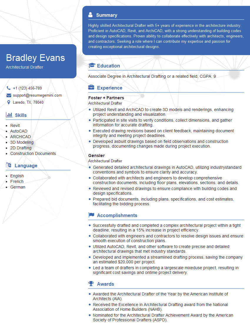
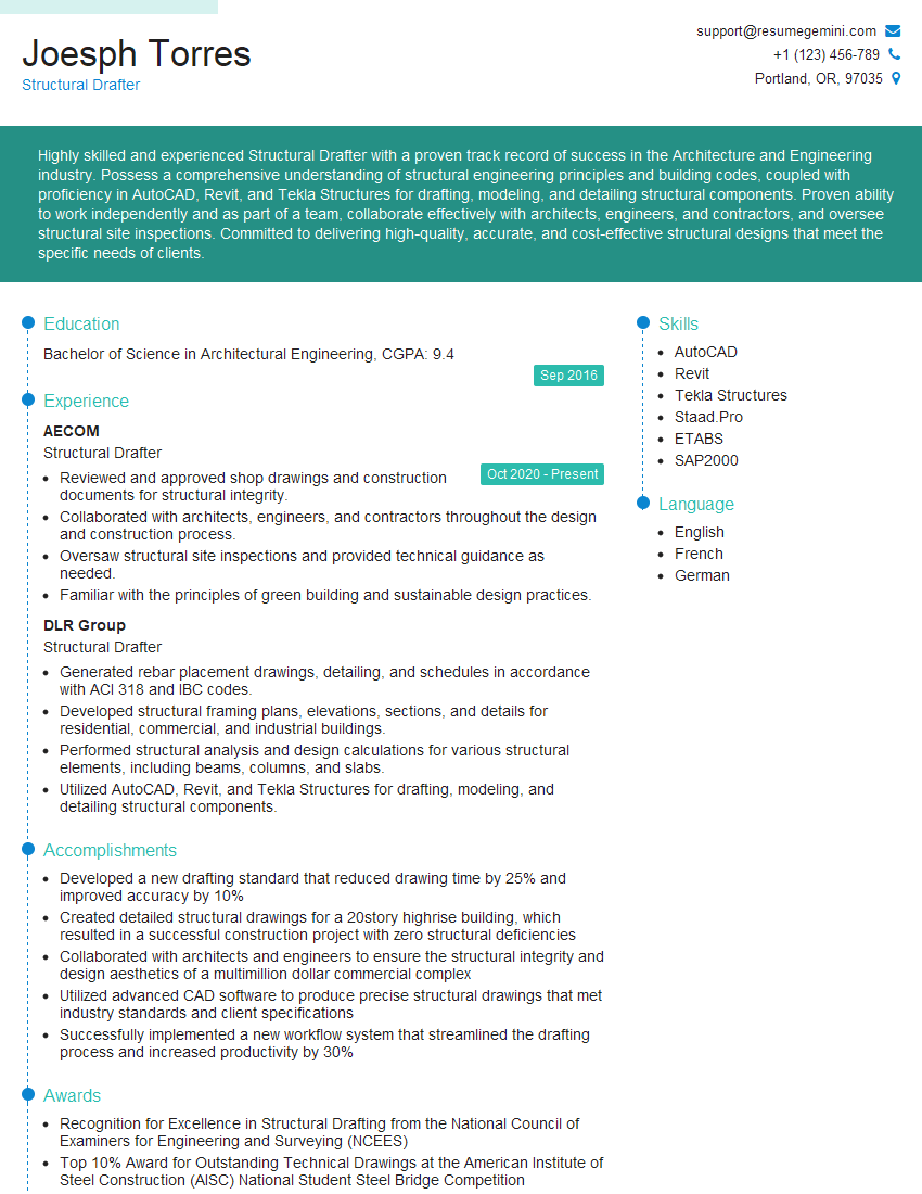
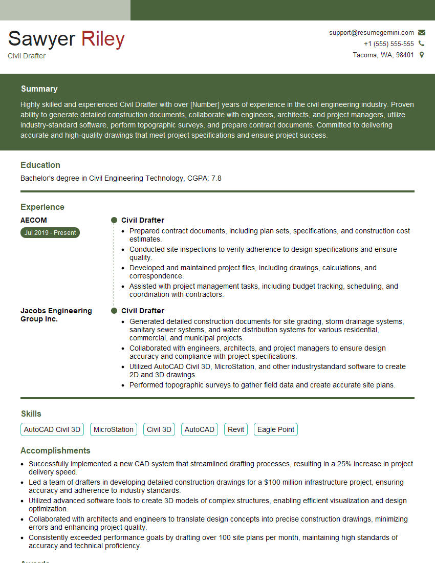
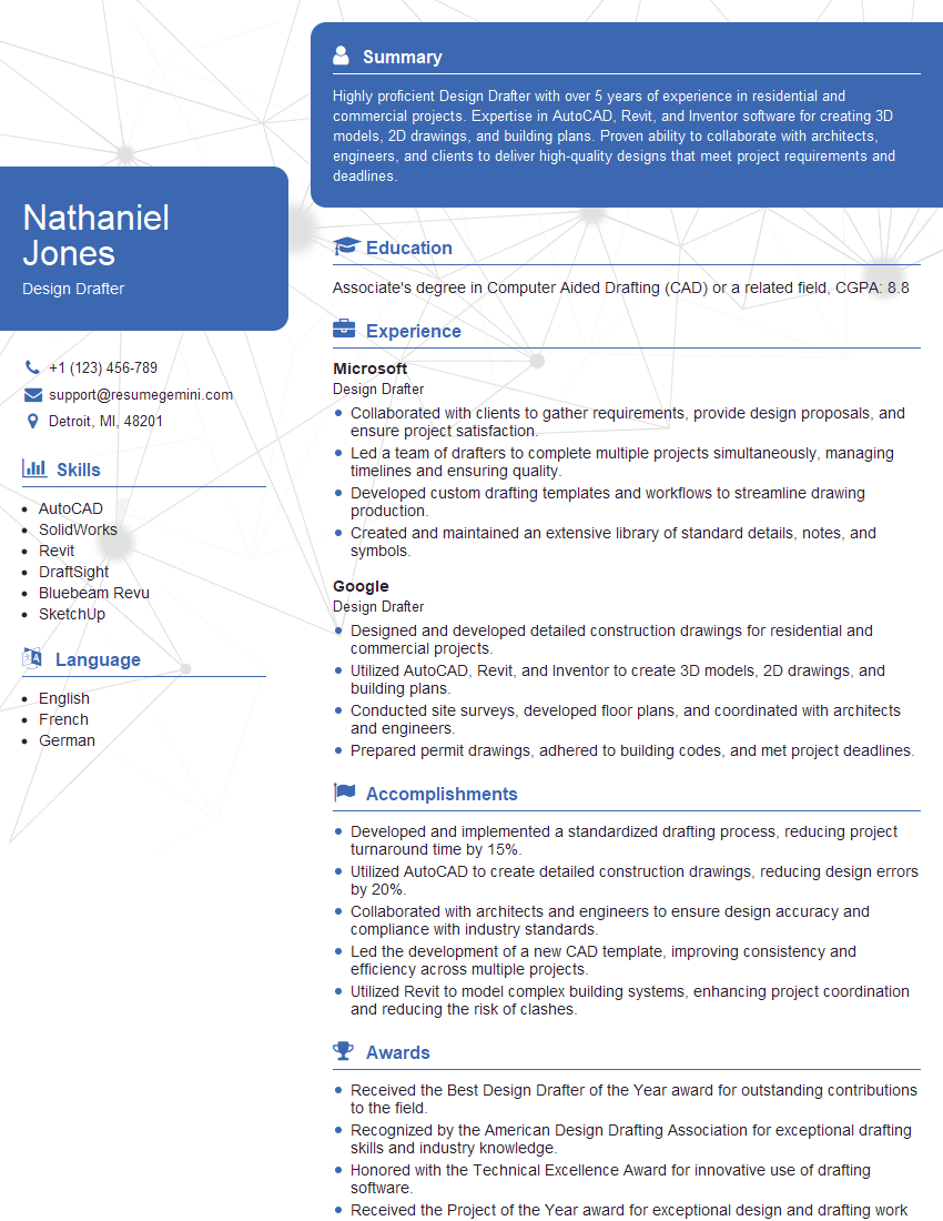
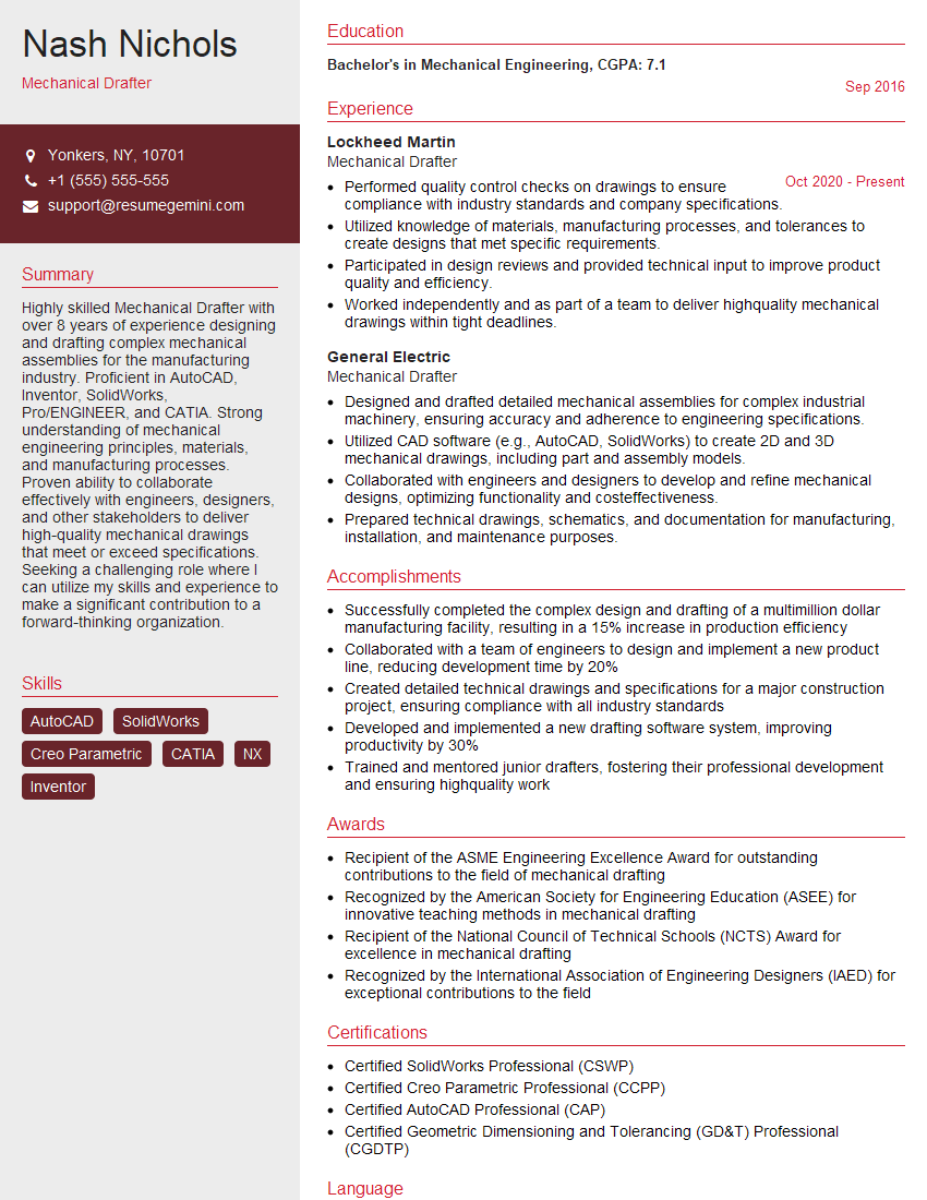
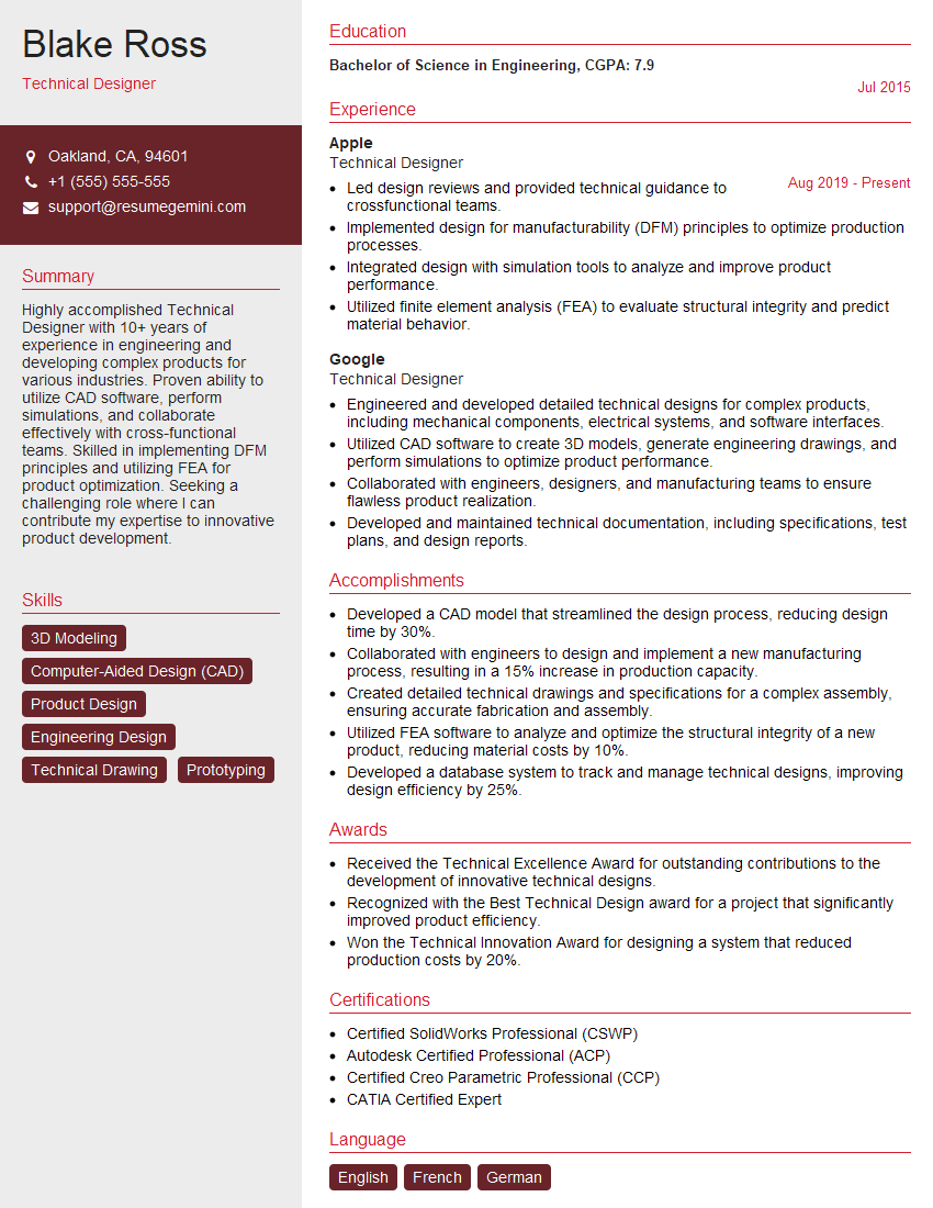
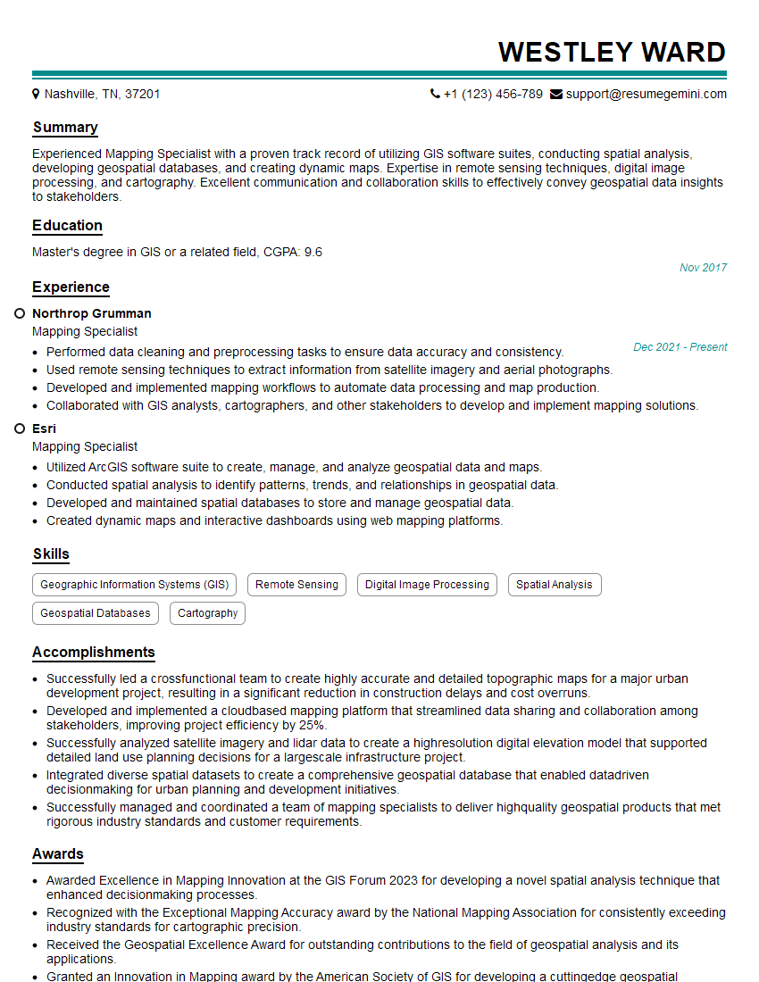
Mastering Drawing in opens doors to exciting career opportunities in illustration, animation, game design, and many more creative fields. To maximize your job prospects, creating a strong, ATS-friendly resume is essential. ResumeGemini is a trusted resource that can help you build a professional resume that highlights your skills and experience effectively. Examples of resumes tailored to Drawing in are available to help you get started.
Explore more articles
Users Rating of Our Blogs
Share Your Experience
We value your feedback! Please rate our content and share your thoughts (optional).
What Readers Say About Our Blog
Hello,
We found issues with your domain’s email setup that may be sending your messages to spam or blocking them completely. InboxShield Mini shows you how to fix it in minutes — no tech skills required.
Scan your domain now for details: https://inboxshield-mini.com/
— Adam @ InboxShield Mini
Reply STOP to unsubscribe
Hi, are you owner of interviewgemini.com? What if I told you I could help you find extra time in your schedule, reconnect with leads you didn’t even realize you missed, and bring in more “I want to work with you” conversations, without increasing your ad spend or hiring a full-time employee?
All with a flexible, budget-friendly service that could easily pay for itself. Sounds good?
Would it be nice to jump on a quick 10-minute call so I can show you exactly how we make this work?
Best,
Hapei
Marketing Director
Hey, I know you’re the owner of interviewgemini.com. I’ll be quick.
Fundraising for your business is tough and time-consuming. We make it easier by guaranteeing two private investor meetings each month, for six months. No demos, no pitch events – just direct introductions to active investors matched to your startup.
If youR17;re raising, this could help you build real momentum. Want me to send more info?
Hi, I represent an SEO company that specialises in getting you AI citations and higher rankings on Google. I’d like to offer you a 100% free SEO audit for your website. Would you be interested?
Hi, I represent an SEO company that specialises in getting you AI citations and higher rankings on Google. I’d like to offer you a 100% free SEO audit for your website. Would you be interested?
good
