Feeling uncertain about what to expect in your upcoming interview? We’ve got you covered! This blog highlights the most important Technical Drawing and Specifications interview questions and provides actionable advice to help you stand out as the ideal candidate. Let’s pave the way for your success.
Questions Asked in Technical Drawing and Specifications Interview
Q 1. Explain the difference between orthographic and isometric projections.
Orthographic and isometric projections are both ways to represent a 3D object in a 2D drawing, but they achieve this in fundamentally different ways. Think of it like taking photos of a building. Orthographic projection is like taking multiple photos from straight on – front, side, and top – each showing only two dimensions. Isometric projection is more like a single, slightly distorted photo taken from a specific angle that shows all three dimensions at once.
Orthographic Projection: This method uses multiple views (typically front, top, and side) to show the object’s dimensions and features completely. Each view shows only two dimensions of the object, effectively ‘flattening’ one dimension. These views are arranged according to standardized conventions to accurately represent the object. For example, the top view is typically placed directly above the front view.
Isometric Projection: This method creates a single view that shows all three dimensions (height, width, and depth) simultaneously. It’s often used for quick visualization and isn’t dimensionally accurate, requiring some interpretation and often supplemented by notes. While all three axes are visible, they are foreshortened, meaning lengths along them appear smaller than in reality, leading to the characteristic slightly distorted look.
In short: Orthographic projections are accurate and precise, ideal for detailed manufacturing, while isometric projections provide a quick, readily understandable overall representation of a 3D shape. Imagine designing a complex machine part: Orthographic drawings would be crucial for manufacturing, while an isometric sketch could help clients visualize the finished product.
Q 2. Describe your experience with various CAD software (AutoCAD, Revit, SolidWorks, etc.).
Throughout my career, I’ve extensively used several CAD software packages, each tailored for different aspects of the design process. My experience includes:
- AutoCAD: Proficient in 2D drafting and detailing, creating precise drawings, utilizing layers, blocks, and annotation tools. I’ve used it for architectural plans, site surveys, and detailed mechanical drawings, often working on large, multi-sheet projects.
- Revit: Extensive experience in 3D building information modeling (BIM). I’ve utilized Revit to create complete building models, from structural framing and MEP systems to finishes and landscaping. The ability to coordinate with other disciplines and produce detailed schedules has been invaluable in my role. I’m adept at utilizing Revit’s families and creating custom content to ensure specific project needs are met.
- SolidWorks: My proficiency extends to 3D modeling, using SolidWorks for creating detailed mechanical components and assemblies. I’m comfortable working with part modeling, assembly design, and generating detailed manufacturing drawings with dimensions and tolerances. I’ve found it extremely useful for creating prototypes and simulating functionality.
My experience extends beyond simple modeling and drawing. I’m proficient in data management, version control and collaborative workflows within these platforms.
Q 3. How do you ensure accuracy and precision in your technical drawings?
Accuracy and precision in technical drawings are paramount. A single error can lead to costly mistakes during manufacturing or construction. To ensure accuracy, I employ several strategies:
- Precise measurements and calculations: I always verify dimensions and calculations multiple times, using software’s built-in verification tools and independent checks. For example, I might use the area calculation tool in AutoCAD to check manually calculated areas.
- Consistent units and scales: I rigorously maintain consistent units (metric or imperial) and scales throughout the drawing. I check these values frequently to prevent accidental mixing.
- Geometric constraints: In CAD software, I use geometric constraints and relations to ensure precise relationships between design elements. This helps to prevent errors from propagating through the model.
- Regular quality checks: I perform regular internal reviews and quality checks for dimensional accuracy, completeness of information, and adherence to relevant standards and conventions. A second pair of eyes is always beneficial before releasing drawings.
- Employing CAD software effectively: using the inherent tools for checking dimensions and geometric relationships, as well as layer and block management, is vital.
By combining meticulous attention to detail with effective use of CAD software capabilities, I ensure the highest level of accuracy and precision in my work.
Q 4. What are the common standards and conventions followed in technical drawing?
Technical drawing adheres to various national and international standards and conventions to ensure clarity, consistency, and effective communication. Some prominent examples include:
- ISO (International Organization for Standardization): ISO standards provide guidelines for various aspects of technical drawing, including dimensioning, tolerancing, and projection methods. These standards are widely adopted globally.
- ANSI (American National Standards Institute): ANSI standards offer similar guidelines, predominantly used in the United States and other countries.
- ASME (American Society of Mechanical Engineers): ASME standards are particularly relevant for mechanical engineering drawings, specifying detailed requirements for various components and assemblies.
Conventions include consistent use of line types (solid, dashed, centerlines, etc.), annotation placement, and layering techniques. For instance, using specific line weights to represent different features ensures clarity in the drawing. These standards and conventions prevent ambiguity and make technical drawings universally understandable.
Q 5. Explain the importance of dimensioning and tolerancing in technical drawings.
Dimensioning and tolerancing are crucial aspects of technical drawings as they define the size, shape, and allowable variations of components. Without them, manufacturing would be impossible, and parts would not fit together correctly.
Dimensioning: This process specifies the exact sizes and locations of features on a part using precise measurements. Clear and unambiguous dimensioning avoids ambiguity and ensures that the manufacturer understands exactly what is required.
Tolerancing: This defines the allowable variations in dimensions. Manufacturing processes are never perfectly accurate, so tolerancing accounts for these variations. Tolerances are expressed using various methods, such as plus/minus values (e.g., 10 ± 0.1 mm) or geometric dimensioning and tolerancing (GD&T) symbols. GD&T uses symbols to specify the permissible variation in form, orientation, location, and runout of features.
Example: A dimension might read “10 mm ± 0.1 mm.” This means the manufactured part can be anywhere between 9.9 mm and 10.1 mm and still be considered acceptable. Without tolerancing, the manufacturer would need to achieve perfect 10mm precision, which is rarely feasible and cost-prohibitive.
Q 6. How do you handle revisions and updates to existing technical drawings?
Handling revisions and updates to technical drawings is crucial to maintain accuracy and reflect changes in design or manufacturing processes. I follow a structured approach:
- Revision control system: I use a revision control system, either within the CAD software or a dedicated version control system, to track changes over time. This allows easy access to previous versions and helps trace the history of modifications. This usually involves numbering revisions, noting the date and description of changes.
- Clear revision marks: Revisions are clearly marked on the drawings themselves, typically using a revision block or table. This quickly communicates the changes to all stakeholders.
- Change logs and documentation: A detailed change log documents the reason for each revision, ensuring the rationale behind modifications is preserved. This is important for traceability and auditing.
- Notification: All relevant parties are informed of revisions, ensuring everyone is working with the most up-to-date drawings.
This methodical approach guarantees clarity and allows for easy tracking of any changes or errors introduced. This is absolutely vital in collaborative projects.
Q 7. Describe your experience with creating and interpreting technical specifications.
Creating and interpreting technical specifications is a critical part of my work. Specifications provide the detailed, written instructions to accompany drawings, detailing material properties, manufacturing processes, and quality control requirements. My experience encompasses:
- Creating specifications: I collaborate closely with engineers and other stakeholders to define clear and concise specifications, addressing every aspect of the product or component. This includes specifying materials (with grades and tolerances), manufacturing processes (e.g., machining, welding, casting), surface finishes, and quality control tests.
- Interpreting specifications: I’m able to interpret existing specifications to ensure compliance with standards and to guide the design and manufacturing processes. Understanding the implications of various clauses within specifications is critical for successful project completion.
- Using standard formats: I’m familiar with various standard formats for specifications, including those defined by industry bodies. Consistency in formatting is essential for clarity and ease of communication. A commonly used format might involve separate sections for material specifications, manufacturing requirements, quality control, and testing procedures.
Accurate and comprehensive specifications are essential to prevent ambiguities and ensure that the final product meets the required standards. My experience in writing and understanding detailed specifications ensures projects proceed smoothly and meet required specifications.
Q 8. How do you manage large and complex drawing projects?
Managing large, complex drawing projects requires a structured approach. Think of it like orchestrating a symphony – each instrument (drawing, specification) plays a crucial part. My strategy involves breaking down the project into manageable modules. This might involve dividing a building design into architectural, structural, MEP (Mechanical, Electrical, Plumbing), and landscaping drawings, each assigned to a team or individual. We utilize a robust project management system, often integrated with our CAD software, to track revisions, deadlines, and collaboration. This system allows for version control, ensuring everyone works from the most up-to-date files. We employ rigorous quality checks at each stage, incorporating peer reviews and automated checks for errors in dimensions and annotations. Finally, clear communication channels are essential – regular meetings, progress reports, and a centralized document repository keep everyone informed and aligned.
For example, on a recent large-scale hospital project, we divided the drawings into 50 distinct modules, assigning responsibility to specialized teams. Our project management system tracked over 1000 revisions, ensuring a seamless integration of all drawings and specifications.
Q 9. Explain your understanding of different drawing scales.
Drawing scales represent the ratio between the dimensions on a drawing and the actual dimensions of the object. Understanding scales is fundamental; an incorrectly scaled drawing can lead to disastrous consequences in construction. Common scales include 1:1 (full size), 1:10 (one unit on the drawing represents ten units in reality), 1:50, 1:100, and 1:200. The choice of scale depends on the size and complexity of the project. Large projects often utilize smaller scales to fit the entire design on manageable sheets, while detailed components might require larger scales for clarity. We always clearly indicate the scale used on each drawing sheet to avoid confusion.
For instance, a site plan might use a scale of 1:500 to show the entire site, while a detail drawing of a window might use a scale of 1:10 or even 1:5 for precision.
Q 10. What are your preferred methods for creating detailed sections and elevations?
Creating detailed sections and elevations requires meticulous attention to detail and a good understanding of architectural principles. I typically use CAD software to generate these drawings. The process begins with a thorough understanding of the 3D model (often created using BIM software), which allows for dynamic sectioning and elevation extraction. I then add detailed annotations, dimensions, and material specifications. For complex geometries, I utilize the software’s capabilities to create intricate sections and elevations with ease. Visual clarity is paramount, employing consistent line weights, hatching patterns, and annotation styles to ensure the drawings are both informative and easy to read. I often utilize the software’s rendering capabilities to create realistic visualizations for better client understanding.
For example, when detailing a complex roof structure, creating multiple sections at varying angles allows us to clearly communicate the intricacies of the design, ensuring the construction team has all the necessary information for precise execution.
Q 11. How do you ensure drawings are compliant with relevant building codes and regulations?
Compliance with building codes and regulations is crucial. I ensure compliance by referring to the relevant codes applicable to the project’s location and type (e.g., IBC, NFPA). These codes are integrated into the design process from the outset. We employ checklists and templates tailored to specific codes to track compliance throughout the design stages. Regular reviews and cross-checking with the specifications are critical. Furthermore, we collaborate closely with structural, mechanical, electrical, and plumbing engineers to ensure all aspects of the design meet the required standards. We document all compliance measures taken and maintain a record of approvals and relevant certifications.
A recent example involved meticulously checking all fire-rated assemblies against the NFPA life safety codes, meticulously documenting each element’s compliance to avoid any construction delays or safety hazards.
Q 12. Describe your experience working with different drawing formats (DWG, DXF, PDF).
I have extensive experience working with various drawing formats, including DWG (AutoCAD’s native format), DXF (a neutral exchange format), and PDF (a widely compatible document format). DWG is my primary format for creating and editing drawings due to its rich functionality and features. DXF serves as a valuable tool for exchanging files between different CAD software platforms. PDFs are used for sharing final drawings with clients and contractors, ensuring the visual representation remains consistent across different devices and software. My proficiency extends to handling various versions of these formats, ensuring compatibility across different software versions and platforms.
In practice, I often start with a DWG file, then export a DXF version for collaborators using different software, finally producing a PDF for distribution and archiving.
Q 13. How familiar are you with BIM (Building Information Modeling)?
I am highly familiar with BIM (Building Information Modeling). BIM represents a significant advancement in the architectural, engineering, and construction industries. It moves beyond 2D drawings to create intelligent 3D models that contain comprehensive information about a building’s design and construction. My experience encompasses working with various BIM software platforms (such as Revit, ArchiCAD). I understand how to create, manage, and collaborate on BIM projects, utilizing the software’s tools for clash detection, quantity takeoffs, and schedule coordination. The ability to extract 2D drawings from a 3D BIM model enhances efficiency and accuracy, minimizing errors and conflicts during construction.
For example, on a recent project, using BIM’s clash detection functionality prevented costly rework by identifying conflicts between the HVAC system and structural elements before construction began.
Q 14. Explain your experience with creating and managing drawing layers.
Managing drawing layers is critical for organization and efficiency in complex projects. Layers are essentially organizational tools within CAD software, allowing you to group related elements (e.g., walls, doors, windows, annotations) for better control and manipulation. A well-structured layer system ensures clarity and ease of editing. My approach involves establishing a clear layer naming convention that reflects the project’s elements. For example, I use descriptive names like “01_Architecture_Walls,” “02_Structure_Columns,” “03_MEP_Plumbing.” This helps identify and manage elements quickly. Furthermore, I use layer properties to control the visibility and print settings of each layer, enabling me to selectively show or hide elements as needed. This is essential for creating different drawing sheets (e.g., architectural plans, structural drawings) without creating multiple files.
Using a well-structured layer system on a recent project allowed us to quickly isolate and modify specific aspects of the design without affecting other elements. This significantly reduced the time and effort required for revisions.
Q 15. How do you use annotations and callouts effectively in your drawings?
Effective annotation and callouts are crucial for clear communication in technical drawings. They provide additional information beyond the visual representation, guiding the reader to understand dimensions, materials, and manufacturing processes. I use a structured approach:
- Clear and Concise Labeling: I ensure all annotations are easily readable and unambiguous, using standardized abbreviations and symbols whenever possible. For instance, instead of writing “Diameter,” I use the standard Ø symbol followed by the dimension.
- Strategic Placement: Annotations are positioned to avoid cluttering the drawing while remaining close to the relevant features. Leader lines, with arrowheads pointing precisely to the feature being referenced, are consistently used.
- Consistent Formatting: I maintain consistent font sizes, styles, and units throughout the drawing, enhancing readability and minimizing confusion. This also includes consistent use of tolerances (e.g., ±0.1 mm).
- Effective Callouts: For complex assemblies or detailed features, I utilize callouts – detailed views or sections – to provide a clearer understanding. Each callout is clearly labeled and referenced back to the main drawing. For example, a callout might show a magnified view of a critical threaded connection, with clearly indicated thread pitch and diameter.
- Balloon Numbers and Tables: For parts lists or multiple components, I use balloon numbers to associate specific items with their descriptions in a parts list table. This links the visual representation to textual information, ensuring accurate identification of each component.
For example, in a drawing of a complex mechanical assembly, I might use a callout to show a detailed cross-section of a specific bearing, annotated with its dimensions, material type (e.g., ‘AISI 52100 Steel’), and tolerance specifications. This level of detail ensures that manufacturing and assembly personnel have all the necessary information.
Career Expert Tips:
- Ace those interviews! Prepare effectively by reviewing the Top 50 Most Common Interview Questions on ResumeGemini.
- Navigate your job search with confidence! Explore a wide range of Career Tips on ResumeGemini. Learn about common challenges and recommendations to overcome them.
- Craft the perfect resume! Master the Art of Resume Writing with ResumeGemini’s guide. Showcase your unique qualifications and achievements effectively.
- Don’t miss out on holiday savings! Build your dream resume with ResumeGemini’s ATS optimized templates.
Q 16. Describe your process for checking drawings for errors before final submission.
My drawing checking process is thorough and multi-stage to minimize errors before submission. It involves both automated checks and manual reviews:
- Automated Checks: I use software tools with built-in design rule checks to automatically detect potential issues like missing dimensions, inconsistencies in units, and geometrical errors. These tools highlight potential problems which I then examine.
- Dimension Check: I manually verify all dimensions, ensuring they are accurately calculated, appropriately placed, and match the design specifications. I also check tolerance values are realistic and appropriate for the manufacturing process.
- Geometric Tolerance Verification: Beyond dimensions, I verify geometric tolerances (GD&T) for critical features, ensuring they are correctly applied and meet the design requirements. This might involve checking the form, orientation, location, and runout of specific features.
- Material Specification Check: I meticulously review all material specifications, ensuring they align with the design requirements and are feasible in manufacturing. I will often cross-reference against material standards and ensure manufacturability.
- Peer Review: Before final submission, I always seek a peer review from a colleague. A fresh pair of eyes can often spot errors that I might have missed.
- Checklist: I use a checklist to ensure all aspects of the drawing are covered, including titles, revisions, approval signatures, and necessary annotations. This structured approach eliminates the risk of overlooking any crucial details.
I treat this quality check as a crucial phase, not simply a formality. A single error in a drawing can lead to costly delays and production issues down the line. Therefore, a comprehensive review process is vital to ensure accuracy and avoid potential problems.
Q 17. How do you collaborate with other team members on large drawing projects?
Collaboration on large drawing projects requires effective communication and the use of collaborative tools. My approach combines:
- Centralized Data Management: We use a centralized platform (e.g., a cloud-based storage system with version control) for storing and accessing all project files. This ensures everyone works with the most up-to-date version, minimizing confusion and conflicts.
- Regular Meetings: Consistent meetings – perhaps daily or weekly depending on project complexity – are held to discuss progress, resolve issues, and coordinate efforts. Clear agendas and meeting minutes are maintained to ensure accountability.
- Clearly Defined Roles and Responsibilities: To avoid redundancy and conflicts, we establish clear roles and responsibilities from the start. Each team member is assigned specific tasks and areas of responsibility within the drawing.
- Communication Tools: We utilize instant messaging and email for quick communication and clarification on specific details. This is supplemented by the use of video conferencing for more complex discussions.
- Design Review Sessions: We hold formal design review sessions where the entire team examines the drawings for completeness, accuracy, and compliance with specifications. This allows for collective problem-solving and ensures everyone is on the same page.
Imagine a team designing a large industrial plant. Using a centralized platform, specific team members could work simultaneously on distinct parts of the design, knowing that their updates are immediately available to the entire team, and design review sessions prevent costly misalignments later on.
Q 18. Explain your understanding of material specifications.
Material specifications are crucial in technical drawings, dictating the properties and characteristics of the components being designed. They ensure consistent quality, manufacturability, and performance. My understanding covers:
- Material Identification: Accurate identification using standard material designations (e.g., ASTM, SAE, ISO standards) is vital. This ensures everyone understands the exact material being used.
- Mechanical Properties: Understanding the mechanical properties of the materials is essential. This includes tensile strength, yield strength, hardness, ductility, and others, as these dictate the component’s ability to withstand stresses and loads.
- Chemical Composition: For some applications, the precise chemical composition of the material is critical (e.g., alloys). This information is included in the specifications to ensure consistent performance.
- Finish and Coatings: Surface finishes, such as plating, painting, or powder coating, can significantly impact a component’s performance and appearance. The required finish is detailed in the specifications.
- Compliance and Standards: Material selection must comply with relevant industry standards and regulations (e.g., safety, environmental). This ensures the component meets the required legal and safety guidelines.
For example, specifying ‘AISI 304 Stainless Steel’ ensures the use of a specific grade of stainless steel known for its corrosion resistance. Adding a surface finish requirement of ‘electropolished’ further enhances its corrosion resistance, illustrating the necessity of clear material specifications.
Q 19. How do you handle conflicting information in technical drawings or specifications?
Conflicting information in technical drawings or specifications is a serious issue, potentially leading to costly errors. My approach to resolving such conflicts involves:
- Identify and Document: The first step is to meticulously identify all conflicting information, clearly documenting each discrepancy.
- Source Verification: The next step is to determine the source and reliability of each piece of conflicting information. This might involve checking the revision history of the drawings, consulting with designers, or referring to authoritative documents.
- Resolution Through Consultation: If the conflict is unclear, I consult with relevant stakeholders – designers, engineers, and project managers – to reach a consensus on the correct information. This discussion often involves weighing the implications of each option.
- Document Resolution: Once a resolution is reached, it must be documented clearly in a formal manner, updating the drawing and specifications accordingly. This documentation ensures everyone is aware of the decision made and the rationale behind it.
- Revision Control: Changes implemented to resolve conflicts should be tracked using a robust revision control system. This ensures that any subsequent revisions account for the resolution of the conflict.
For instance, if one drawing shows a dimension of 10 mm while another indicates 15 mm for the same feature, I would carefully investigate both sources and consult with the design team to confirm the correct value. Then, a change order and drawing revision would reflect the decision along with the rationale and the approval signature(s).
Q 20. How do you prioritize tasks when working on multiple drawing projects simultaneously?
When juggling multiple drawing projects, effective prioritization is key. I employ a strategy combining urgency and importance:
- Prioritization Matrix: I use a prioritization matrix, often a simple quadrant chart, to categorize tasks based on urgency (deadline proximity) and importance (impact on overall project success). This helps visualize which tasks require immediate attention.
- Time Blocking: I dedicate specific blocks of time to each project, focusing on high-priority tasks during periods of peak concentration. This allows for focused attention and minimizes task-switching.
- Realistic Scheduling: I create realistic schedules that account for unforeseen delays and complexities. This includes buffer time for unexpected tasks or difficulties.
- Communication and Delegation: Open communication with stakeholders is essential to manage expectations and adjust priorities as needed. When possible, I delegate less critical tasks to free up time for higher-priority items.
- Regular Review and Adjustment: I regularly review my schedule and priorities, making adjustments as needed. This ensures that the prioritization remains relevant to evolving project needs.
For example, a critical client deadline for one project would be categorized as ‘high urgency, high importance’, demanding immediate focus, whereas a less time-sensitive internal documentation task might be ‘low urgency, medium importance’, allowing for later attention.
Q 21. What is your experience with creating detailed assembly drawings?
I have extensive experience creating detailed assembly drawings, which involve illustrating the relationships between multiple components within a larger assembly. My process emphasizes clarity and precision:
- Exploded Views: I frequently use exploded views to show the individual components and how they fit together, improving understanding of the assembly sequence.
- Part Numbering and Identification: Each component is clearly identified with its part number, referencing a separate parts list for detailed specifications.
- Bill of Materials (BOM): A detailed BOM accompanies the assembly drawing, providing a comprehensive list of all components, their quantities, and material specifications.
- Assembly Instructions: Clear and concise assembly instructions are sometimes included, guiding the assembler through the process.
- 3D Modeling Integration: I often integrate 3D modeling software to create assembly drawings, utilizing the software’s capabilities to generate various views and sections effortlessly.
- Revision Control: All assembly drawings are managed with a revision control system to ensure accuracy and consistency.
Creating a detailed assembly drawing for a complex piece of machinery, like a gearbox, would involve carefully illustrating each gear, bearing, shaft, housing, etc., with proper annotations, exploded views to show assembly, and a comprehensive parts list. This detailed documentation ensures efficient manufacturing and maintenance.
Q 22. How do you incorporate client feedback into your drawings?
Incorporating client feedback is crucial for successful project delivery. My approach involves a structured process. First, I schedule a dedicated review session where I present the drawings and actively solicit feedback. I encourage open communication, making sure clients feel comfortable expressing their concerns or suggestions, no matter how minor they may seem. I use visual aids during the review, zooming in on specific areas to clarify details. Next, I meticulously document all feedback, categorizing it by priority and nature (e.g., design changes, dimensional corrections, material specifications). This documented feedback serves as a clear roadmap for revisions. Finally, I implement the approved changes, clearly indicating revisions in the updated drawings using revision clouds and notes to maintain a clear audit trail. For instance, on a recent residential design project, the client requested a larger window in the kitchen. I documented the change request, adjusted the drawing, and clearly marked the alteration with a revision cloud and a note explaining the change. This transparent process ensures that the final drawings accurately reflect the client’s vision and minimizes the risk of costly rework later.
Q 23. Explain your understanding of different types of lines used in technical drawings.
Technical drawings employ a variety of lines, each with a specific meaning. Understanding these line types is fundamental for clear communication. Think of it like a language – each symbol has a distinct role. Here are some common types:
- Object Lines (Solid lines): These define the visible outlines of objects. They are thick and continuous, like the bold lines you see outlining a building in a blueprint.
- Hidden Lines (Dashed lines): These represent features that are not directly visible from the chosen view. Imagine a hole drilled inside a block; the hole’s edges would be shown using dashed lines.
- Center Lines (Thin, dashed lines alternating with short spaces): These indicate centers of symmetry or rotational features. They are useful for showing the center of a circle or a symmetrical component.
- Dimension Lines (Thin lines terminated by arrowheads): These show the size and location of features, often including numerical dimension values. They provide crucial measurements for manufacturing or construction.
- Section Lines (Hatching): Used to indicate a cut-away view of an object, revealing internal features. Different hatch patterns might signify different materials.
- Leader Lines (Thin lines ending in an arrowhead or dot): These lines connect a note or dimension to the feature it refers to, helping to clarify specific details.
- Break Lines (Zigzag lines): Indicate a break in an object, simplifying the drawing of long, repetitive features. It’s a way to shorten a long straight line representing a component while still showing that the component continues further along.
Proficiency in using these lines ensures accuracy and clarity in the drawings, preventing misinterpretations and errors during manufacturing or construction.
Q 24. Describe your experience with creating and managing drawing templates.
Creating and managing drawing templates is essential for maintaining consistency and efficiency. I typically create templates that incorporate company standards, including title blocks, sheet sizes, and preferred line weights. This ensures uniformity across all projects. My templates include pre-defined layers for different drawing elements (e.g., dimensions, annotations, object lines), making it easier to organize and manage complex drawings. Furthermore, I use a system of version control, usually through file naming conventions and a revision history within the drawing itself, ensuring that the correct version of the template is always used and that all revisions are documented. A well-structured template significantly streamlines the design process and reduces the possibility of errors, ensuring a professional and consistent output. For example, my templates include automated features that generate title blocks with the correct project information upon opening, saving a significant amount of time and preventing common title block errors.
Q 25. How familiar are you with different types of drawing views (e.g., isometric, section, detail)?
I’m very familiar with various drawing views. Each provides a different perspective to convey a complete picture of the object. Let’s consider a few examples:
- Orthographic Projections (Multiview): These consist of multiple views (front, top, side) showing the object from different angles. They are essential for accurate representation of dimensions and shapes.
- Isometric Views: These offer a three-dimensional representation of the object at a single viewpoint. They are helpful for visualizing the overall form but may not be as precise as orthographic views for dimensional measurements.
- Section Views: These show the object as if it were cut open, revealing internal features. This is particularly useful for complex parts or assemblies.
- Detail Views: These are magnified views of specific areas requiring more detailed information. For example, a small threaded feature might be shown in a detail view to clarify thread specifications.
- Auxiliary Views: These are supplemental views used when a feature is inclined and needs to be represented clearly.
My experience includes selecting the most appropriate views depending on the complexity of the object and the information that needs to be conveyed. The selection of views is crucial for avoiding ambiguity and ensuring that the drawing communicates its intended purpose effectively. For instance, designing a complex gearbox would require multiple orthographic views and a section view to show the internal gear meshing clearly.
Q 26. How do you ensure the clarity and legibility of your drawings?
Clarity and legibility are paramount. I ensure this through a combination of techniques. First, I adhere to relevant drawing standards (e.g., ISO, ANSI) which define line weights, text styles, and overall presentation standards. Using consistent line weights and styles prevents visual clutter and improves readability. Secondly, I make effective use of layers and annotation. Organizing drawing elements into distinct layers allows for easy manipulation and editing. Annotations such as dimensioning and notes are strategically placed to avoid cluttering the drawing, using leaders to connect them clearly to the appropriate features. Thirdly, I use appropriate scaling. Choosing the correct scale avoids drawings that are either too cramped or excessively large. I also use clear and concise labeling, ensuring all components are properly identified. Finally, I employ a consistent font and text size throughout the drawing. This enhances readability and gives the drawing a professional appearance.
Q 27. Describe your experience with using different types of drawing tools (both digital and manual).
My experience encompasses both manual and digital drawing tools. In the past, I worked extensively with traditional tools like drafting boards, T-squares, triangles, scales, and technical pens. This experience gave me a strong foundation in drafting techniques and instilled an appreciation for precision and accuracy. Today, I primarily use digital tools such as AutoCAD, SolidWorks, and Inventor. I am proficient in using these software packages to create 2D and 3D models, detailed drawings, and assemblies. My digital skills allow for efficient creation, modification, and management of drawings. I also leverage features like layer management, revision tracking, and automated annotation capabilities. The transition to digital tools has significantly increased efficiency while maintaining the precision required for technical drawings. Both manual and digital experience have provided a comprehensive understanding of the principles and best practices in creating technical documentation.
Key Topics to Learn for Your Technical Drawing and Specifications Interview
- Orthographic Projection: Understanding first-angle and third-angle projections, creating and interpreting multi-view drawings. Practical application: Accurately representing complex 3D objects in 2D for manufacturing.
- Dimensioning and Tolerancing: Mastering GD&T (Geometric Dimensioning and Tolerancing) symbols and their application to ensure consistent part manufacturing. Practical application: Communicating precise manufacturing requirements to prevent errors and ensure quality control.
- Section Views and Auxiliary Views: Creating and interpreting section views to reveal internal features and auxiliary views to show inclined surfaces accurately. Practical application: Clearly communicating complex internal geometries for assembly and manufacturing.
- Isometric and Perspective Drawings: Creating and interpreting isometric and perspective drawings for visualization and communication. Practical application: Presenting design concepts to clients or teams in an easily understandable format.
- Reading and Interpreting Technical Specifications: Understanding material specifications, surface finishes, and manufacturing processes described in technical documents. Practical application: Ensuring accurate interpretation of engineering design intent for manufacturing and quality control.
- CAD Software Proficiency: Demonstrating competency in relevant CAD software (AutoCAD, SolidWorks, etc.) and its application in creating and manipulating technical drawings. Practical application: Efficiently creating and managing design data throughout the product development lifecycle.
- Blueprint Reading and Interpretation: Understanding the language of blueprints and effectively extracting relevant information. Practical application: Successfully collaborating with engineers, manufacturers, and contractors on projects.
- Problem-solving in Technical Drawing: Analyzing drawing discrepancies, identifying potential errors, and proposing solutions. Practical application: Demonstrating strong analytical and problem-solving skills vital to the engineering process.
Next Steps
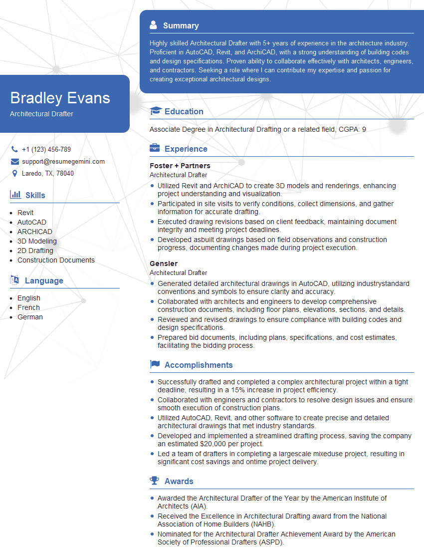
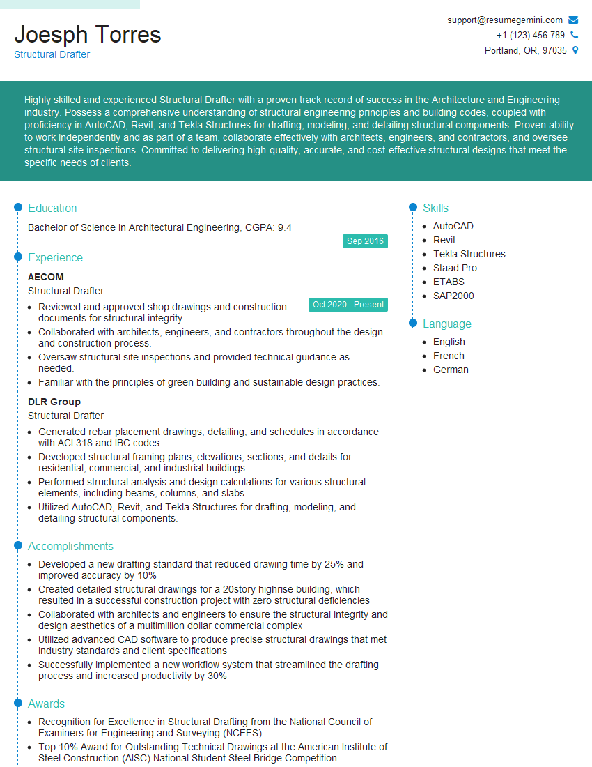
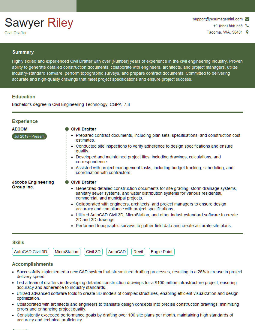
Mastering Technical Drawing and Specifications is crucial for a successful career in engineering and related fields. A strong grasp of these skills demonstrates your ability to communicate complex design ideas clearly and effectively, a highly valued asset in any technical role. To maximize your job prospects, it’s essential to create an ATS-friendly resume that highlights your expertise. We strongly recommend using ResumeGemini to build a professional and impactful resume that showcases your skills and experience effectively. ResumeGemini provides examples of resumes tailored specifically to Technical Drawing and Specifications professionals to help you get started. Take the next step and craft a resume that truly reflects your capabilities!
Explore more articles
Users Rating of Our Blogs
Share Your Experience
We value your feedback! Please rate our content and share your thoughts (optional).
What Readers Say About Our Blog
Hello,
We found issues with your domain’s email setup that may be sending your messages to spam or blocking them completely. InboxShield Mini shows you how to fix it in minutes — no tech skills required.
Scan your domain now for details: https://inboxshield-mini.com/
— Adam @ InboxShield Mini
Reply STOP to unsubscribe
Hi, are you owner of interviewgemini.com? What if I told you I could help you find extra time in your schedule, reconnect with leads you didn’t even realize you missed, and bring in more “I want to work with you” conversations, without increasing your ad spend or hiring a full-time employee?
All with a flexible, budget-friendly service that could easily pay for itself. Sounds good?
Would it be nice to jump on a quick 10-minute call so I can show you exactly how we make this work?
Best,
Hapei
Marketing Director
Hey, I know you’re the owner of interviewgemini.com. I’ll be quick.
Fundraising for your business is tough and time-consuming. We make it easier by guaranteeing two private investor meetings each month, for six months. No demos, no pitch events – just direct introductions to active investors matched to your startup.
If youR17;re raising, this could help you build real momentum. Want me to send more info?
Hi, I represent an SEO company that specialises in getting you AI citations and higher rankings on Google. I’d like to offer you a 100% free SEO audit for your website. Would you be interested?
Hi, I represent an SEO company that specialises in getting you AI citations and higher rankings on Google. I’d like to offer you a 100% free SEO audit for your website. Would you be interested?
good
