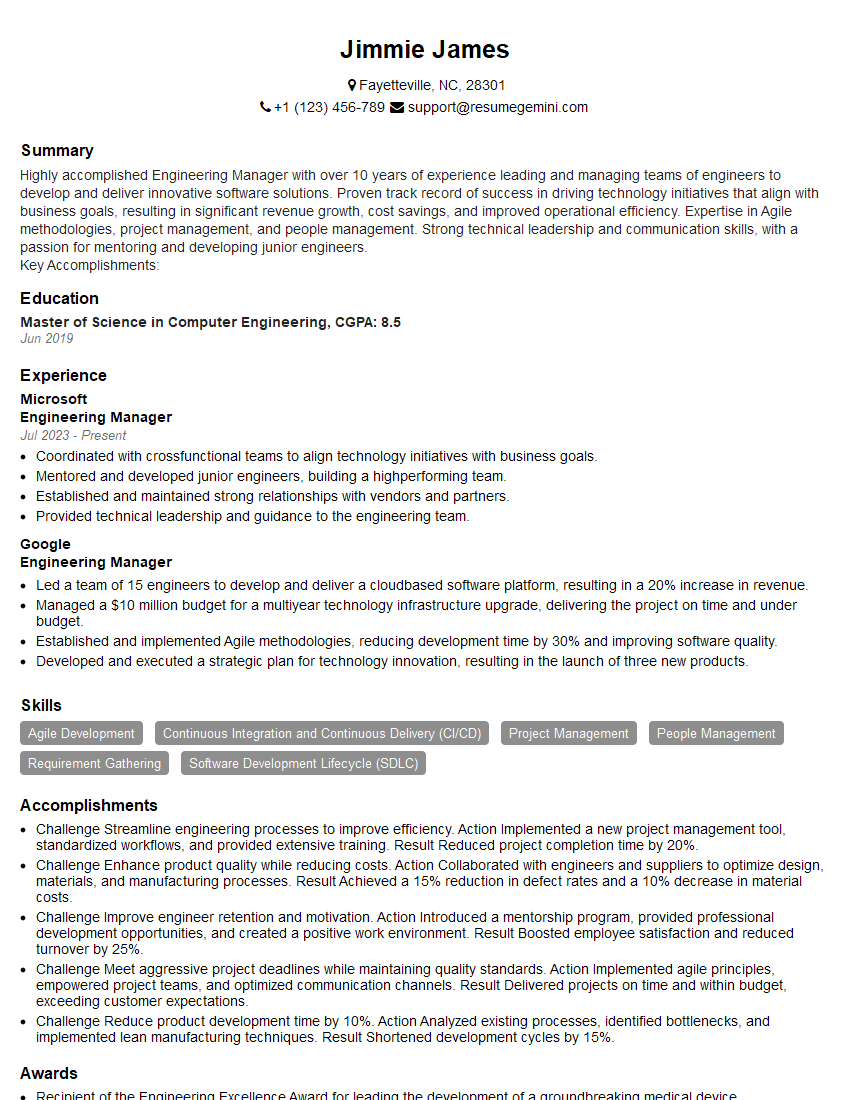
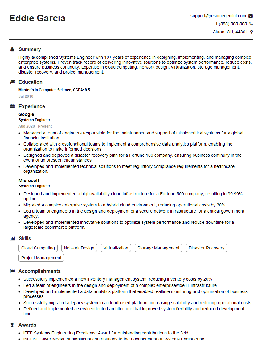
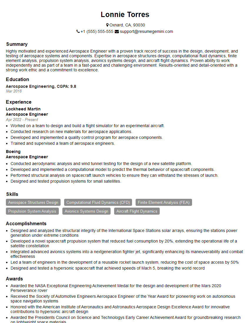
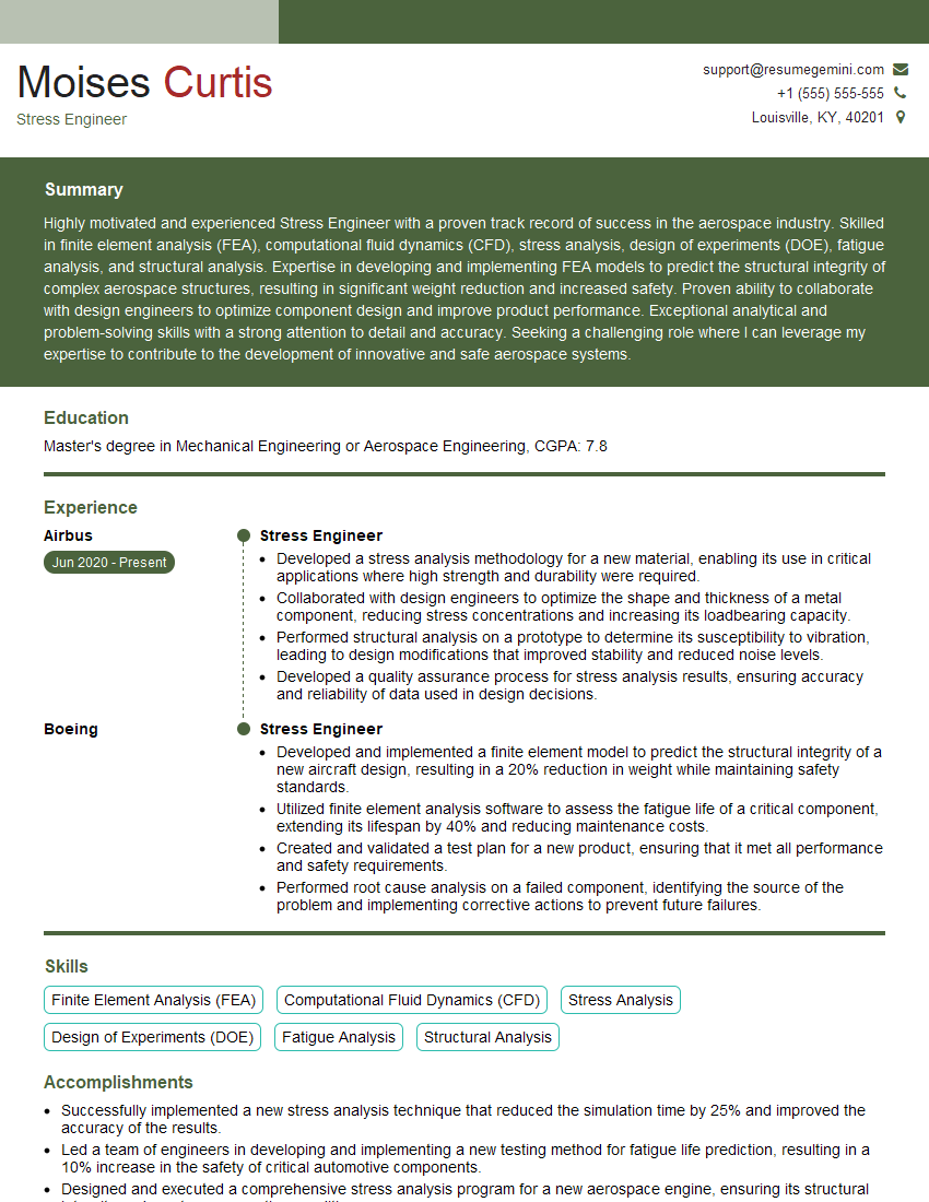
Are you ready to stand out in your next interview? Understanding and preparing for Design of Mechanical Systems interview questions is a game-changer. In this blog, we’ve compiled key questions and expert advice to help you showcase your skills with confidence and precision. Let’s get started on your journey to acing the interview.
Questions Asked in Design of Mechanical Systems Interview
Q 1. Explain the design process you typically follow.
My design process is iterative and follows a structured approach, broadly adhering to a modified version of the V-model. It begins with a thorough requirements definition phase, where I collaborate closely with stakeholders to understand the functional and non-functional needs of the system. This involves detailed discussions, creating functional specifications, and identifying key performance indicators (KPIs).
Next comes the conceptual design phase, where I generate multiple design concepts, sketching and brainstorming potential solutions. These are evaluated against the requirements using criteria like cost, manufacturability, and performance. This stage often utilizes quick, hand-drawn sketches and simple calculations to eliminate infeasible options early. The chosen concept then proceeds to the detailed design phase. Here, I utilize CAD software to create detailed 3D models and 2D drawings, incorporating detailed dimensions, tolerances, and material specifications. This is accompanied by rigorous analysis, including tolerance analysis, stress analysis (often FEA), and manufacturability studies.
The prototype and testing phase involves creating physical prototypes (or virtual ones using simulation) and rigorously testing them to validate the design against the requirements and KPIs. Any discrepancies are then addressed in an iterative manner, returning to earlier phases as needed. Finally, the manufacturing and deployment phase involves working with manufacturers to ensure the design is produced according to specifications and to oversee the implementation of the final product. Throughout the entire process, detailed documentation is maintained and regular progress reports are issued to stakeholders.
Q 2. Describe your experience with CAD software (e.g., SolidWorks, AutoCAD).
I have extensive experience with several CAD software packages, most notably SolidWorks and AutoCAD. In SolidWorks, I’m proficient in creating complex 3D models, performing simulations, generating detailed drawings, and managing design data effectively. I use SolidWorks’ simulation capabilities extensively for stress analysis and motion studies. My SolidWorks skills extend to advanced techniques like surface modeling, parametric design, and design automation. AutoCAD, on the other hand, is primarily used for creating 2D drawings, particularly for manufacturing documentation, detailed assembly drawings, and generating fabrication instructions. I find both programs crucial, with SolidWorks focusing on the 3D design and simulation aspects, and AutoCAD for the more detailed, precise 2D documentation often required for manufacturing processes.
For example, in a recent project involving the design of a robotic arm, I used SolidWorks to model the kinematic linkages, perform motion simulations to ensure smooth operation and avoid collisions, and then generate detailed assembly drawings. AutoCAD was then used to create precise manufacturing drawings for the individual components, ensuring accurate dimensions and tolerances for the CNC machining process.
Q 3. How do you perform tolerance analysis in your designs?
Tolerance analysis is a critical aspect of mechanical design, ensuring that components fit and function as intended despite manufacturing variations. I typically employ a combination of techniques, beginning with a clear understanding of the permissible variation in each dimension. This involves referring to manufacturing capabilities and considering the impact of each tolerance on overall system performance. I use statistical methods, often employing Monte Carlo simulations, to determine the probability of assembly issues arising from tolerance stack-up.
For example, if designing a cylindrical shaft fitting into a hole, I’d meticulously define the tolerances on the shaft diameter and hole diameter. Using statistical methods, I’d model the probability distributions for these dimensions, taking into account the manufacturing process’ capabilities and then simulate multiple assemblies. The simulation would reveal the probability of interference (too tight) or excessive clearance (too loose), allowing me to optimize tolerances for optimal assembly while minimizing manufacturing costs. Geometric Dimensioning and Tolerancing (GD&T) standards are rigorously applied to ensure clear communication of tolerance requirements on drawings, thus avoiding ambiguity during manufacturing.
Q 4. What are your preferred methods for stress analysis and FEA?
My preferred methods for stress analysis and Finite Element Analysis (FEA) involve utilizing commercially available software packages like ANSYS and Abaqus. These offer powerful tools for simulating complex stress distributions under various loading conditions. For simpler designs, I may use hand calculations using classical mechanics principles, particularly when quick estimations are sufficient. For complex geometries or loading conditions, FEA is indispensable. The choice between ANSYS and Abaqus depends on the specific requirements of the analysis; ANSYS is generally easier to use for many standard analyses, whereas Abaqus is preferred for more advanced simulations requiring highly customized material models or sophisticated contact definitions.
For instance, when designing a pressure vessel, I would use FEA to simulate the stress distribution under internal pressure, ensuring the vessel’s design can withstand the expected load without failure. The FEA would inform the selection of appropriate materials, wall thicknesses, and reinforcement strategies.
Q 5. How do you handle design changes and revisions during a project?
Design changes and revisions are an inherent part of the engineering design process. I manage them effectively through a robust change management system that includes version control within my CAD software and a clearly defined change request process. Each change is documented, analyzed for its impact on the overall design, and approved by relevant stakeholders before implementation. Impact assessments are crucial to ensure that modifications don’t introduce unintended consequences in other parts of the system. For example, a seemingly minor change to a component’s dimension might have unforeseen implications on its interaction with other components. The change management system ensures these impacts are identified and addressed proactively.
In a recent project, a late-stage change request required modifying the mounting interface of a sub-assembly. This involved a thorough impact analysis to ensure the change didn’t affect the overall system stability or functionality. Using version control within SolidWorks, we tracked all changes, allowing for easy rollback if needed, and documented the rationale for each modification. This rigorous approach maintained design integrity while ensuring we met the client’s evolving needs.
Q 6. Explain your experience with different manufacturing processes.
I have experience with a range of manufacturing processes, including CNC machining (milling and turning), 3D printing (SLA, FDM, SLS), casting (sand casting, investment casting), injection molding, and sheet metal fabrication. My understanding extends beyond simply knowing the processes; I also understand the design considerations specific to each process. This is critical for designing manufacturable products that meet cost, quality, and lead-time requirements. For example, designing for injection molding requires understanding draft angles, parting lines, and material flow considerations to ensure successful mold filling. Similarly, CNC machining requires careful consideration of tool accessibility and part clamping to optimize machining efficiency and prevent damage.
In a previous project, we had to choose between CNC machining and injection molding for producing a plastic enclosure. By carefully analyzing factors like part complexity, production volume, and cost, we determined that injection molding was the most cost-effective and efficient approach for high-volume production. This involved designing the enclosure to be optimized for injection molding, including appropriate draft angles and rib structures for strength and stiffness.
Q 7. Describe a challenging design problem you solved and how you approached it.
One challenging design problem I encountered involved designing a compact, lightweight, and highly reliable mechanism for deploying a solar array on a small satellite. The challenge stemmed from the need to minimize weight, volume, and power consumption, while ensuring reliable operation in the harsh conditions of space. The initial design faced issues with jamming due to friction and wear, and there were limitations on the available actuation power. To address this, I used a multi-pronged approach.
Firstly, I conducted extensive simulations using FEA and kinematic analysis to identify the stress points and potential friction areas within the mechanism. This revealed the need for optimized geometry and material selection to minimize friction and wear. Next, I incorporated a novel lubrication system that utilized a low-outgassing lubricant specifically designed for space applications. Finally, we implemented a redundant deployment mechanism as a backup for increased reliability. This involved incorporating a secondary deployment system that could activate if the primary mechanism failed. The final design successfully passed all testing, demonstrating the required reliability and efficiency, achieving a significant reduction in weight and volume compared to the initial design. The experience highlighted the importance of iterative design, thorough analysis, and the incorporation of redundancy for mission-critical systems.
Q 8. How do you ensure the manufacturability of your designs?
Ensuring manufacturability is paramount in mechanical design. It’s not just about creating a functional design; it’s about creating one that can be efficiently and cost-effectively produced. I approach this through a multi-faceted strategy.
Early Collaboration with Manufacturing Experts: I involve manufacturing engineers early in the design process. This allows us to identify potential issues and incorporate manufacturing constraints proactively, rather than reacting to them later.
Design for Manufacturing (DFM) Principles: I rigorously apply DFM principles, considering factors like material selection, part geometry, assembly methods, and tooling requirements. For example, minimizing the number of parts, using standard components, and designing for ease of assembly significantly reduces manufacturing costs and complexity.
Tolerance Analysis: A thorough tolerance analysis is crucial. This involves defining acceptable variations in dimensions and ensuring they are achievable through the chosen manufacturing processes. Overly tight tolerances can make manufacturing difficult and expensive, while overly loose tolerances might compromise functionality.
Process Capability Studies: Whenever feasible, I involve process capability studies to verify that the chosen manufacturing processes can consistently produce parts within the specified tolerances. This helps avoid costly rework or scrap.
Material Selection: Material selection plays a crucial role. Choosing materials readily available and easily machinable or formable directly influences manufacturability and cost.
For example, in a project designing a robotic arm, early collaboration with a CNC machining specialist helped us optimize the part geometries to minimize machining time and material waste, leading to a 15% cost reduction.
Q 9. What is your experience with material selection for different applications?
Material selection is a critical aspect of mechanical design, heavily dependent on the specific application’s requirements. My experience encompasses a wide range of materials and applications.
Strength and Stiffness: For structural components needing high strength and stiffness, I’ve used materials like steel alloys (e.g., high-strength low-alloy steel, stainless steel), titanium alloys, and carbon fiber composites. The choice depends on factors like weight constraints, environmental conditions, and cost.
Durability and Corrosion Resistance: In applications requiring high durability and corrosion resistance, I’ve specified materials like stainless steel, aluminum alloys (with protective coatings), and polymers with UV resistance. For instance, choosing marine-grade stainless steel for a marine application prevents corrosion.
Lightweight Applications: For applications where weight is a critical factor, such as aerospace or automotive components, I’ve utilized lightweight materials like aluminum alloys, magnesium alloys, and carbon fiber composites. These offer a good strength-to-weight ratio.
Biocompatibility: When designing medical devices, I’ve focused on biocompatible materials like titanium, certain polymers, and specific grades of stainless steel to ensure safety and prevent adverse reactions.
I utilize material selection databases and software to access material properties and compare various options based on cost, availability, and performance criteria. This ensures an informed decision leading to optimal material selection for every application.
Q 10. How do you manage project timelines and budgets?
Managing project timelines and budgets requires a structured approach and meticulous planning. I utilize several techniques:
Work Breakdown Structure (WBS): I break down the project into smaller, manageable tasks, creating a WBS to clearly define dependencies and milestones. This provides a granular view for effective time and resource allocation.
Critical Path Method (CPM): I use CPM to identify the critical path – the sequence of tasks that determine the shortest possible project duration. This highlights the tasks requiring the most attention to avoid delays.
Gantt Charts: Gantt charts visually represent the project schedule, showing the duration and dependencies of tasks. Regular updates to the Gantt chart help track progress and identify potential schedule slips.
Budget Allocation: I develop a detailed budget that allocates resources to individual tasks. Regular monitoring ensures spending stays within allocated limits.
Risk Management: Identifying potential risks and developing mitigation plans is crucial. This proactive approach helps prevent cost overruns and schedule delays.
Regular Communication: Frequent communication with the project team and stakeholders is essential for transparency and issue resolution. Any deviations from the plan are promptly addressed through change management procedures.
For instance, on a recent project with a tight deadline, utilizing the CPM helped us identify and prioritize critical tasks, allowing us to complete the project on time and within budget despite unforeseen challenges.
Q 11. Explain your understanding of GD&T (Geometric Dimensioning and Tolerancing).
Geometric Dimensioning and Tolerancing (GD&T) is a symbolic language used to precisely define the dimensions and tolerances of parts and assemblies. It’s crucial for ensuring proper fit and function between components. My understanding encompasses:
Basic GD&T Symbols: I’m proficient in using symbols like straightness, flatness, circularity, cylindricity, parallelism, perpendicularity, angularity, position, concentricity, and runout to define geometric tolerances.
Datum References: I understand the importance of establishing datum references (A, B, C) to provide a stable and consistent basis for defining tolerances. This is key for ensuring proper assembly and part functionality.
Tolerance Zones: I can define and apply tolerance zones to specify the acceptable variations in geometric characteristics. The size and shape of tolerance zones vary depending on the application and required precision.
Feature Control Frames (FCFs): I use FCFs to comprehensively define tolerances, including the type of tolerance, zone size, and datum references. This is crucial for clarity in manufacturing specifications.
Material Condition Modifiers: I understand the use of material condition modifiers (e.g., MMC, LMC) to specify tolerances relative to the maximum or minimum material condition. This can affect the size of the tolerance zone.
GD&T’s rigorous approach minimizes ambiguity and ensures that manufactured parts meet the design specifications, leading to successful assemblies and improved product quality. Incorrect GD&T can lead to parts not fitting correctly and manufacturing failures.
Q 12. Describe your experience with design for manufacturing (DFM).
Design for Manufacturing (DFM) is an iterative process that considers manufacturing constraints early in the design stage. My experience with DFM involves a systematic approach:
Part Simplification: I aim to reduce the number of parts and simplify geometries to lower manufacturing costs and assembly time. This often involves integrating multiple parts into a single component.
Standard Parts and Components: I prioritize using commercially available, standard parts and components whenever possible. This avoids costly custom tooling and reduces lead times.
Material Selection for Manufacturing: I select materials that are readily available, easy to process (e.g., machining, casting, molding), and compatible with the chosen manufacturing processes. This minimizes manufacturing costs and ensures efficient production.
Tolerance Optimization: I meticulously define tolerances that are achievable with the chosen manufacturing processes while ensuring proper part function. Unrealistic tolerances can lead to significant rework and scrap.
Assembly Considerations: I design for ease of assembly, considering factors such as accessibility, fastener selection, and alignment features. This reduces assembly time and minimizes potential errors.
Process Capability Analysis: I often conduct process capability analyses to validate that the selected manufacturing processes can consistently meet the specified tolerances and quality requirements.
In one project involving a complex assembly, applying DFM principles led to a 20% reduction in manufacturing costs and a 30% reduction in assembly time by simplifying part geometries and using standardized components.
Q 13. How do you conduct design reviews and incorporate feedback?
Design reviews are an essential part of the design process, allowing for collaborative evaluation and improvement. My approach is structured and comprehensive:
Formal Review Process: I conduct formal design reviews at various stages of the design cycle, involving relevant stakeholders like engineers, manufacturing specialists, and potentially clients.
Checklist-Driven Reviews: I use checklists to ensure consistent evaluation of design aspects like functionality, manufacturability, safety, and cost. This keeps the review process objective and thorough.
Constructive Feedback: I encourage constructive feedback during design reviews, fostering a collaborative environment where all participants feel comfortable expressing their concerns and suggestions.
Action Item Tracking: All feedback and action items are documented and tracked meticulously. This ensures that identified issues are addressed and resolved efficiently.
Iterative Design Refinement: I integrate the feedback from design reviews to iterate and refine the design. This iterative approach ensures the final design meets all requirements and addresses potential issues.
For example, a design review of a new pump identified a potential vibration issue that was addressed by modifying the impeller design, preventing costly field failures.
Q 14. What are your experience with different types of mechanical systems?
My experience spans a variety of mechanical systems, including:
Robotics and Automation: I have designed robotic arms, end-effectors, and automated assembly systems. This involved designing mechanisms for precise movement, force control, and efficient operation.
Power Transmission Systems: I have experience designing gearboxes, belt drives, and chain drives for power transmission applications. This required expertise in selecting appropriate components and optimizing gear ratios for efficiency and durability.
Fluid Power Systems: My work has included designing hydraulic and pneumatic systems for various applications. This involved selecting appropriate actuators, valves, and sensors, as well as ensuring system safety and reliability.
Thermal Systems: I have designed heat exchangers, cooling systems, and thermal management solutions for electronic devices and machinery. This required knowledge of thermodynamics and heat transfer principles.
Precision Mechanisms: I have designed and analyzed precision mechanisms such as micro-positioning stages and high-precision actuators, requiring in-depth understanding of tolerance analysis and control systems.
These experiences have provided me with a strong foundation in mechanical design principles and the ability to adapt to different system types and challenges. I’m comfortable working across various disciplines to find optimal solutions.
Q 15. What is your experience with designing for specific industry standards (e.g., ASME, ISO)?
Throughout my career, I’ve consistently worked with industry standards like ASME (American Society of Mechanical Engineers) and ISO (International Organization for Standardization). Understanding these standards is crucial for ensuring designs meet safety, performance, and manufacturing requirements. For example, when designing pressure vessels, I meticulously adhere to ASME Section VIII, Division 1, which dictates the rules for design, fabrication, inspection, and testing. This includes calculations for wall thickness, weld joint design, and pressure testing procedures. Similarly, ISO 9001 principles have guided my work on quality management systems, ensuring consistent product quality and traceability throughout the design and manufacturing process. I’ve also worked on projects that needed to comply with specific industry standards relevant to the automotive and aerospace sectors, each with its own unique requirements and certifications.
Career Expert Tips:
- Ace those interviews! Prepare effectively by reviewing the Top 50 Most Common Interview Questions on ResumeGemini.
- Navigate your job search with confidence! Explore a wide range of Career Tips on ResumeGemini. Learn about common challenges and recommendations to overcome them.
- Craft the perfect resume! Master the Art of Resume Writing with ResumeGemini’s guide. Showcase your unique qualifications and achievements effectively.
- Don’t miss out on holiday savings! Build your dream resume with ResumeGemini’s ATS optimized templates.
Q 16. How do you ensure the safety and reliability of your designs?
Safety and reliability are paramount in my design process. I employ a multi-layered approach, starting with thorough risk assessment. This involves identifying potential failure modes and their consequences using techniques like Failure Modes and Effects Analysis (FMEA). Next, I incorporate robust design principles, including redundancy and fail-safe mechanisms, to mitigate risks. For example, in a critical system, I might include backup components to ensure continued operation in case of primary component failure. Furthermore, I utilize rigorous simulations and analysis (Finite Element Analysis –FEA, for instance) to verify design strength and performance under various loading conditions. Finally, rigorous testing—including prototype testing and life cycle testing—validates the design’s robustness and confirms its ability to meet or exceed safety standards.
Q 17. Describe your proficiency with simulation and analysis tools.
I’m highly proficient in various simulation and analysis tools. My expertise includes Finite Element Analysis (FEA) software like ANSYS and Abaqus, which I use to simulate stress, strain, and deformation under complex loading scenarios. I also use Computational Fluid Dynamics (CFD) software, such as Fluent, to analyze fluid flow and heat transfer in various systems. For example, I used ANSYS to analyze the stress distribution in a complex robotic arm design, optimizing its geometry to reduce weight while maintaining structural integrity. My proficiency also extends to multi-body dynamics simulation software such as Adams, which I’ve used to model and analyze the kinematics and dynamics of mechanical systems involving multiple moving parts, crucial for optimizing the design of mechanisms and robotics systems.
Q 18. Explain your understanding of fatigue and failure analysis.
Fatigue and failure analysis are crucial aspects of my design process. Fatigue failure occurs when a material repeatedly experiences stress below its yield strength, leading to crack initiation and propagation. I use S-N curves (Stress vs. Number of cycles to failure) and Miner’s rule to predict fatigue life. For instance, designing a component subject to cyclic loading, like a piston rod in an engine, requires careful consideration of material properties, stress concentrations, and surface finish to avoid fatigue failure. Failure analysis involves investigating why a component failed. I utilize tools like fractography (examining fracture surfaces), metallography (analyzing microstructure), and root cause analysis to identify the cause of failure and implement corrective actions to prevent recurrence. A case study involved analyzing a broken turbine blade; using fractography, we determined the failure originated from a microscopic inclusion, leading to design changes in material selection and processing.
Q 19. How familiar are you with different types of bearings and their applications?
I have extensive knowledge of various bearing types and their applications. My understanding encompasses ball bearings, roller bearings (cylindrical, tapered, spherical), journal bearings, and thrust bearings. The choice of bearing depends on factors like load type (radial, axial), speed, operating environment, and cost. For high-speed applications, I would likely select ball bearings for their low friction and high rotational speed capabilities. In contrast, roller bearings are preferred for heavy radial loads. For example, in a high-speed motor, I would specify precision ball bearings with low friction characteristics to minimize energy loss. For a heavy-duty conveyor system carrying large loads, however, I might opt for robust roller bearings capable of withstanding high radial stresses. My experience includes selecting and specifying bearings for diverse applications, ensuring optimal performance and long-term reliability.
Q 20. What is your understanding of thermodynamics and fluid mechanics?
Thermodynamics and fluid mechanics are fundamental to my design work. In thermodynamics, I apply principles of energy conservation, heat transfer, and work to optimize systems’ efficiency and performance. This includes analyzing heat exchangers, engines, and refrigeration cycles. For instance, in the design of an internal combustion engine, an understanding of thermodynamics is essential to optimize the combustion process for power output and efficiency while reducing emissions. In fluid mechanics, I analyze fluid flow, pressure drops, and heat transfer in systems involving liquids or gases. This is critical in designing hydraulic systems, piping networks, and cooling systems. For example, designing a cooling system for a high-power electronic device requires understanding fluid flow dynamics to ensure effective heat removal, preventing overheating and system failure. I often use computational tools to model and analyze these complex phenomena.
Q 21. Describe your experience with creating detailed technical drawings and specifications.
I possess significant experience in creating detailed technical drawings and specifications. I’m proficient in using CAD software such as SolidWorks and AutoCAD to generate 2D and 3D models, detailed assembly drawings, and manufacturing drawings. These drawings include dimensions, tolerances, material specifications, surface finishes, and other critical information necessary for manufacturing. Beyond geometry, I create comprehensive specifications that detail performance requirements, testing procedures, and quality control measures. For instance, I recently created a complete set of drawings and specifications for a custom-designed robotic end effector, including detailed assembly drawings showing the interaction of various components and comprehensive specifications outlining performance metrics like grip force and repeatability. Accuracy and clarity are essential in my drawing and specification creation to ensure successful manufacturing and assembly.
Q 22. Explain your approach to testing and validating designs.
My approach to testing and validating designs is multifaceted and iterative, focusing on a combination of analytical methods, simulations, and physical prototyping. It’s crucial to verify that the design meets all functional, performance, and safety requirements.
Initially, I employ Finite Element Analysis (FEA) and Computational Fluid Dynamics (CFD) simulations to predict the structural integrity, thermal behavior, and fluid flow characteristics of the design under various operating conditions. This allows for early identification and mitigation of potential issues. For example, in designing a high-speed centrifugal pump, FEA would help assess stress levels in the impeller, preventing fatigue failure. CFD would optimize the impeller shape for efficient fluid flow.
Following simulation, I create physical prototypes, starting with simpler, lower-fidelity models to test core functionalities and iterate on the design. This could involve 3D printing rapid prototypes for initial testing or building a functional prototype for more rigorous testing. For the pump example, we might build a scaled-down prototype to test flow rates and pressure. As the design matures, higher-fidelity prototypes will be made.
Finally, rigorous testing is conducted. This includes static testing (e.g., tensile strength testing of materials) and dynamic testing (e.g., fatigue and vibration testing) under simulated real-world conditions. Results are meticulously documented and compared to initial predictions. This iterative process ensures continuous refinement and validation of the design.
Q 23. How do you balance design innovation with cost-effectiveness?
Balancing design innovation with cost-effectiveness is a critical aspect of successful engineering. It’s not about sacrificing one for the other, but rather finding creative solutions that meet both objectives.
My approach involves a thorough understanding of the project constraints from the outset, including budget limitations, material costs, manufacturing processes, and time constraints. I then explore various design options, evaluating their technical feasibility, performance characteristics, and associated costs. This often involves using design optimization tools and techniques to identify optimal designs that minimize costs without compromising functionality or performance.
For instance, consider designing a robotic arm. Innovation might involve incorporating advanced sensors or actuators for improved precision and dexterity. However, to maintain cost-effectiveness, I might choose readily available and cost-effective materials, streamlining manufacturing processes, and using off-the-shelf components where appropriate. Careful material selection (using aluminum instead of titanium, for example) can dramatically reduce costs without significantly sacrificing strength. The trade-off is carefully considered and documented.
Value engineering is another vital tool: systematically analyzing every component to determine its value contribution and explore cost-reduction strategies without compromising performance.
Q 24. What is your experience with project management methodologies (e.g., Agile, Waterfall)?
I have extensive experience working with both Agile and Waterfall project management methodologies. The choice of methodology depends largely on the project’s nature, size, and complexity.
In projects with well-defined requirements and minimal anticipated changes, the Waterfall methodology is often suitable. This approach involves a sequential progression through stages – requirements, design, implementation, testing, deployment – ensuring a structured and well-documented process.
However, for projects characterized by evolving requirements, uncertainty, or the need for quick iterations and feedback, Agile methodology proves to be far more effective. Agile emphasizes iterative development, frequent feedback loops, and adaptability. I have extensive experience with Scrum and Kanban within the Agile framework. Scrum’s sprints and daily stand-ups facilitate effective communication and collaboration, allowing for rapid adjustments based on testing and feedback.
Regardless of the chosen methodology, I prioritize clear communication, meticulous documentation, and proactive risk management to ensure successful project completion.
Q 25. Describe your experience with working in a team environment.
I thrive in team environments and believe that collaborative efforts are essential to successful project delivery. Effective teamwork relies on clear communication, mutual respect, and a shared understanding of goals.
In past projects, I’ve actively participated in brainstorming sessions, contributing ideas, providing constructive feedback, and supporting team members. I’m adept at delegating tasks effectively, ensuring that each team member’s skills and expertise are utilized optimally. I believe in a collaborative design process where ideas are shared openly, allowing us to leverage the strengths of everyone on the team.
I’ve also played a role in mentoring junior engineers, providing guidance and support, and fostering a positive and productive work environment. Conflict resolution is key, and I aim to resolve disagreements constructively through open discussion and compromise.
Q 26. How do you stay up-to-date with the latest advancements in mechanical design?
Staying up-to-date with the latest advancements in mechanical design is a continuous process. I actively engage in several strategies to maintain my expertise.
I regularly subscribe to and read industry publications such as Machine Design and Mechanical Engineering. Attending conferences and workshops, such as those offered by ASME (American Society of Mechanical Engineers), provides opportunities to network with peers and learn about cutting-edge technologies and design trends.
Online resources, such as research papers on platforms like IEEE Xplore and ScienceDirect, and professional development courses on platforms like Coursera and edX, are invaluable tools for continuous learning. I actively participate in online forums and communities dedicated to mechanical engineering, exchanging knowledge and insights with other professionals.
Furthermore, I dedicate time to researching new materials, manufacturing processes, and design software. Staying current on these aspects is critical to producing innovative and efficient designs.
Q 27. How do you handle conflicting priorities or tight deadlines?
Handling conflicting priorities or tight deadlines requires a systematic and organized approach. My strategy involves prioritizing tasks based on their urgency and importance, using techniques like the Eisenhower Matrix (urgent/important).
Open communication with stakeholders is crucial to clarify expectations and identify potential compromises. I often work closely with project managers to create realistic schedules and identify potential bottlenecks.
When faced with tight deadlines, I effectively delegate tasks, leverage available resources, and work collaboratively with the team to ensure timely project completion. This may involve optimizing processes, streamlining workflows, and occasionally re-prioritizing tasks based on updated information. Proactive risk management helps mitigate unforeseen issues which might compromise deadlines.
Ultimately, the key is clear and consistent communication to manage expectations and work effectively under pressure.
Q 28. Explain your experience with design optimization techniques.
I have significant experience using design optimization techniques to enhance the performance and efficiency of mechanical systems. These techniques involve employing software and algorithms to systematically explore the design space and identify optimal solutions.
I’m proficient in using optimization algorithms such as genetic algorithms, gradient-based methods, and simulated annealing. These algorithms are used within commercial FEA and CAD software packages to search for the design parameters (dimensions, material properties, etc.) that minimize weight, maximize strength, or optimize other performance metrics subject to various constraints.
For example, in optimizing a gear system, I might use optimization software to determine the optimal gear tooth profile and module to minimize noise and wear, while simultaneously maintaining the required strength and efficiency. The software would iterate through thousands of design variations, subjecting each to FEA to assess stress levels and performance.
Topology optimization is another powerful technique that allows for the exploration of novel shapes and structures that are optimal for a given loading condition. This helps in creating lightweight but strong designs.
Key Topics to Learn for Design of Mechanical Systems Interview
- Kinematics and Dynamics: Understand the principles of motion and forces acting on mechanical systems. This includes analyzing velocities, accelerations, and forces in various mechanisms.
- Stress and Strain Analysis: Learn to apply fundamental stress-strain relationships to analyze components under various loading conditions. This is crucial for ensuring structural integrity.
- Material Selection: Master the properties of different engineering materials and their suitability for specific applications. Consider factors like strength, weight, cost, and manufacturability.
- Failure Theories: Understand different failure modes (fatigue, yielding, fracture) and be prepared to apply relevant theories to predict component lifespan and safety.
- Design for Manufacturing (DFM): Familiarize yourself with manufacturing processes and how design choices impact manufacturability, cost, and quality. This includes considerations for machining, casting, and other methods.
- Computer-Aided Design (CAD): Demonstrate proficiency in using CAD software for creating and analyzing mechanical designs. Be prepared to discuss your experience with specific software packages.
- Finite Element Analysis (FEA): Understand the principles of FEA and its application in analyzing complex mechanical systems. Discuss your experience with FEA software and interpreting results.
- Mechanical Vibrations: Grasp the fundamentals of vibration analysis, including natural frequencies, damping, and resonance. This is vital for designing systems that avoid unwanted vibrations.
- Fluid Mechanics (as applicable): If relevant to the specific role, demonstrate understanding of fluid flow, pressure, and forces within mechanical systems (e.g., pumps, turbines).
- Thermodynamics (as applicable): If the role involves thermal systems, review fundamental thermodynamic principles and their application in design.
Next Steps
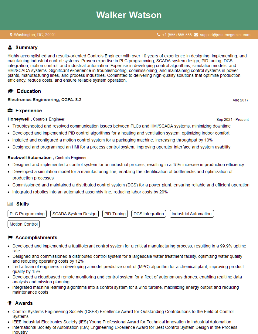
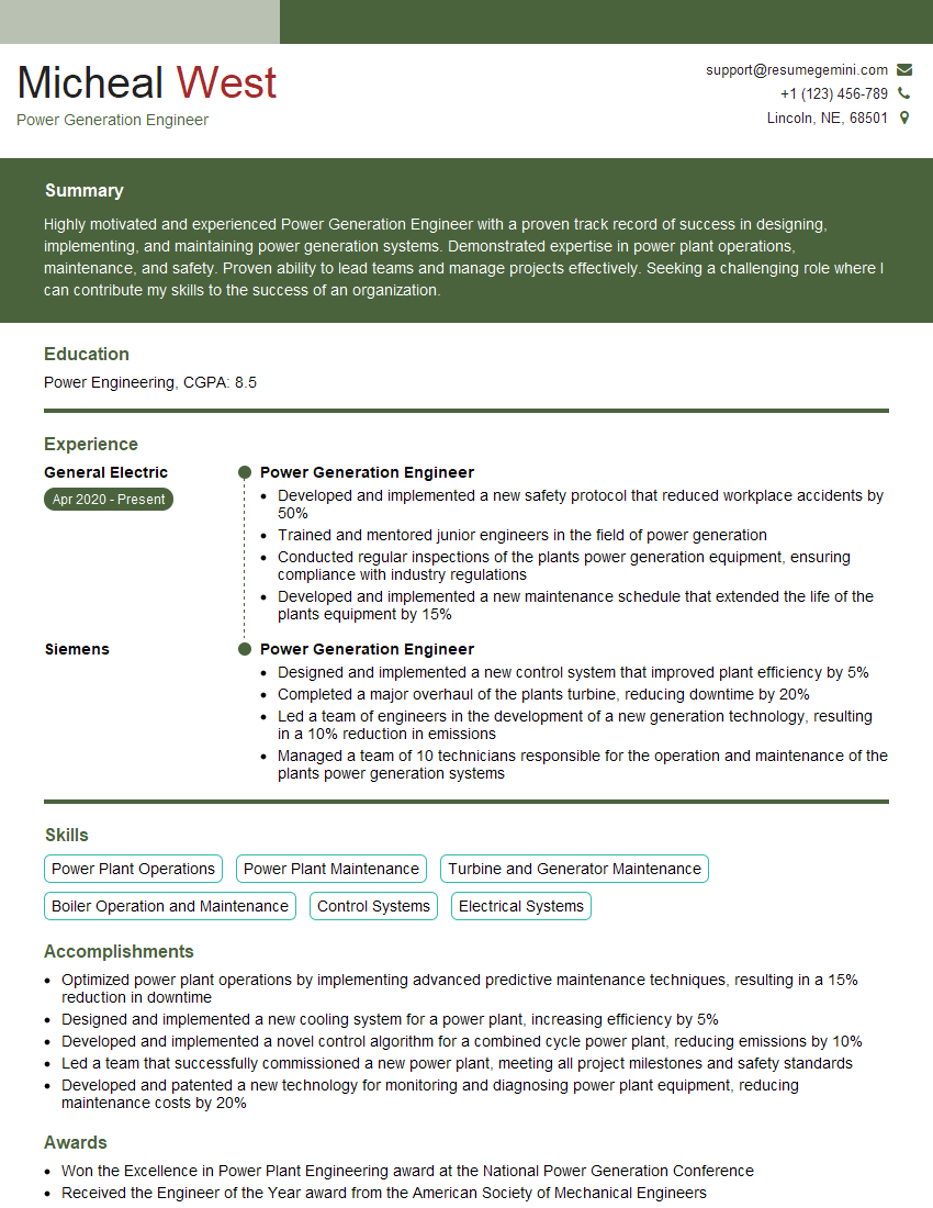
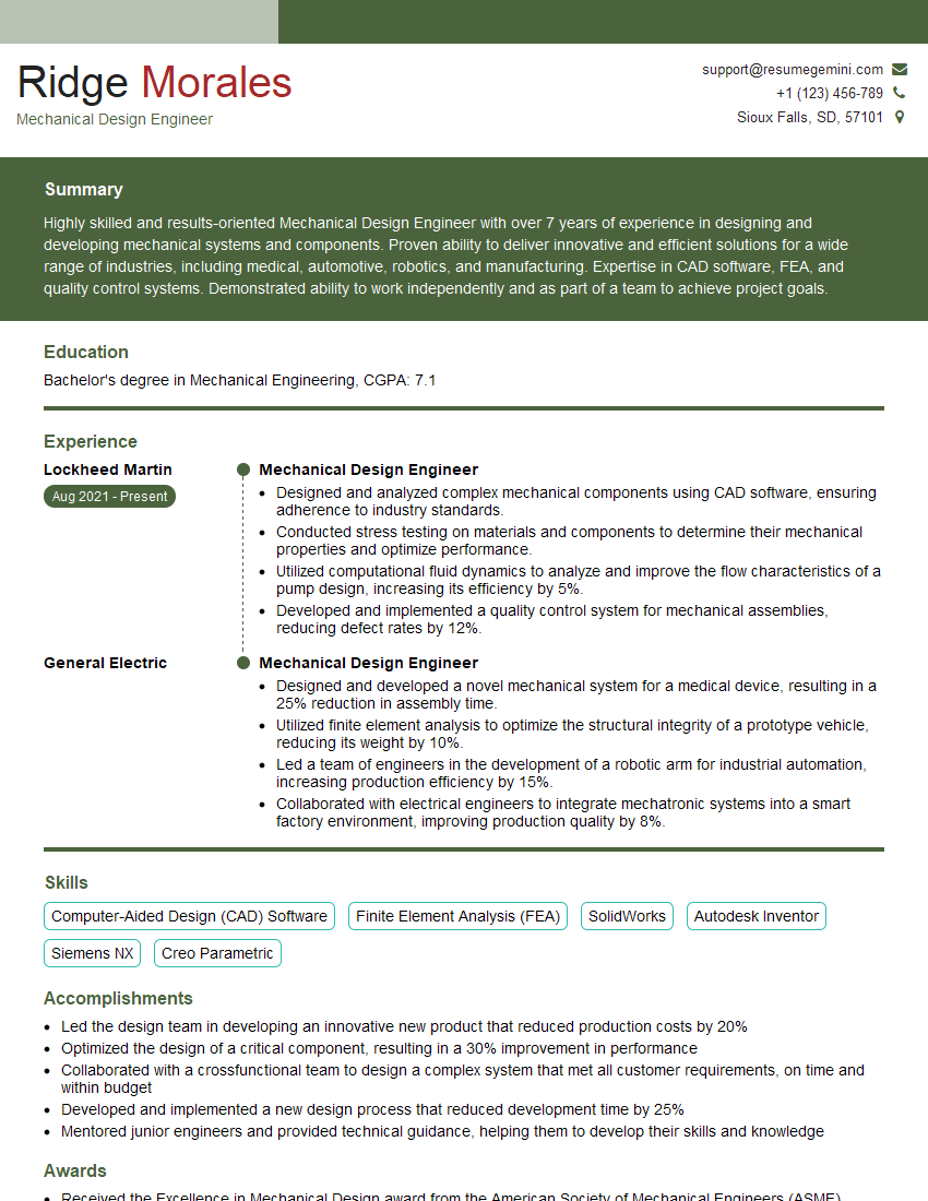
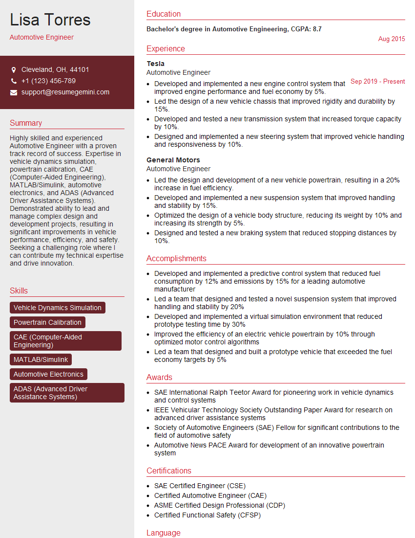
Mastering Design of Mechanical Systems is paramount for a successful and rewarding career. It opens doors to exciting opportunities in diverse fields, allowing you to contribute to innovative projects and technological advancements. To significantly boost your job prospects, it’s crucial to create an ATS-friendly resume that effectively highlights your skills and experience. ResumeGemini is a trusted resource that can help you build a professional and impactful resume. We offer examples of resumes tailored to Design of Mechanical Systems to guide you in showcasing your qualifications effectively. Take the next step towards your dream career – build your winning resume with ResumeGemini today!
Explore more articles
Users Rating of Our Blogs
Share Your Experience
We value your feedback! Please rate our content and share your thoughts (optional).
What Readers Say About Our Blog
Hello,
We found issues with your domain’s email setup that may be sending your messages to spam or blocking them completely. InboxShield Mini shows you how to fix it in minutes — no tech skills required.
Scan your domain now for details: https://inboxshield-mini.com/
— Adam @ InboxShield Mini
Reply STOP to unsubscribe
Hi, are you owner of interviewgemini.com? What if I told you I could help you find extra time in your schedule, reconnect with leads you didn’t even realize you missed, and bring in more “I want to work with you” conversations, without increasing your ad spend or hiring a full-time employee?
All with a flexible, budget-friendly service that could easily pay for itself. Sounds good?
Would it be nice to jump on a quick 10-minute call so I can show you exactly how we make this work?
Best,
Hapei
Marketing Director
Hey, I know you’re the owner of interviewgemini.com. I’ll be quick.
Fundraising for your business is tough and time-consuming. We make it easier by guaranteeing two private investor meetings each month, for six months. No demos, no pitch events – just direct introductions to active investors matched to your startup.
If youR17;re raising, this could help you build real momentum. Want me to send more info?
Hi, I represent an SEO company that specialises in getting you AI citations and higher rankings on Google. I’d like to offer you a 100% free SEO audit for your website. Would you be interested?
Hi, I represent an SEO company that specialises in getting you AI citations and higher rankings on Google. I’d like to offer you a 100% free SEO audit for your website. Would you be interested?
good
