Unlock your full potential by mastering the most common 2D and 3D Sketching interview questions. This blog offers a deep dive into the critical topics, ensuring you’re not only prepared to answer but to excel. With these insights, you’ll approach your interview with clarity and confidence.
Questions Asked in 2D and 3D Sketching Interview
Q 1. What are the key differences between 2D and 3D sketching?
The fundamental difference between 2D and 3D sketching lies in their dimensional representation. 2D sketching confines shapes to a single plane, depicting only length and width. Think of a blueprint – it shows the top, side, and front views of an object, but lacks depth. 3D sketching, however, adds depth, allowing for the representation of objects in three dimensions (length, width, and height), providing a much more realistic and complete representation. This allows for a far better understanding of the object’s form and spatial relationships.
Imagine trying to build a birdhouse from a 2D sketch. You’d have to infer the depth and angles from multiple views. A 3D sketch, on the other hand, provides a complete, visual representation, making construction much simpler and less prone to error.
Q 2. Explain your experience with various CAD software (e.g., AutoCAD, SolidWorks, Revit, SketchUp).
My experience with CAD software is extensive and spans several platforms. I’ve used AutoCAD extensively for 2D drafting, particularly for architectural and mechanical drawings. My proficiency includes creating detailed floor plans, sections, elevations and utilizing features like dimensioning, layers and plotting. SolidWorks is my go-to for 3D modeling, particularly for complex mechanical parts and assemblies. I’m adept at using its features for creating solid models, performing simulations and generating detailed manufacturing drawings. I’ve also used Revit for architectural and structural design, mastering its features for BIM (Building Information Modeling) workflows, including family creation and coordination of building systems. Finally, I’ve worked with SketchUp for quicker conceptual modeling and presentation-quality renders, leveraging its intuitive interface for rapid prototyping.
For example, in one project, I used SolidWorks to model a complex robotic arm, then exported the model to Revit for integration into a larger factory floor design. The combined experience allowed seamless transition between different stages of the project.
Q 3. Describe your workflow for creating a 3D model from a 2D sketch.
My workflow for creating a 3D model from a 2D sketch usually involves several steps. First, I carefully analyze the 2D sketch, paying close attention to dimensions, annotations, and any implied details. Then, I choose the appropriate 3D modeling software based on the complexity of the model and the desired level of detail. In most cases, I start by creating 2D sketches within the 3D software, directly mirroring or interpreting the original 2D drawing.
Next, I use extrusion, revolution, or other 3D modeling tools to add depth to these 2D sketches, transforming them into 3D shapes. For complex geometries, I might use a combination of techniques like lofting or sweeping. Finally, I meticulously refine the 3D model, ensuring all dimensions and details are accurate and consistent with the original 2D sketch. Frequent checks and comparisons with the 2D blueprint are key throughout this process. The 2D drawing acts as a road map while the 3D model brings that map to life.
Q 4. How do you handle complex geometries in 3D modeling?
Handling complex geometries in 3D modeling requires a methodical approach and a deep understanding of the software’s capabilities. I typically break down complex shapes into simpler, more manageable components. This involves identifying fundamental geometric primitives (cubes, cylinders, cones, etc.) that can be combined or modified to create the desired form. Features like Boolean operations (union, subtraction, intersection) are crucial for combining and modifying these simpler shapes.
For highly complex organic shapes, I might utilize techniques like surface modeling, creating a smooth surface from curves and points. Parametric modeling is also a powerful tool, allowing for modification of the model through changes to input parameters, making design iteration smoother. Consistent use of constraints and relations helps maintain accuracy and control during the modeling process. For instance, I once modeled a car chassis by separately modeling each component – body, engine, suspension – and assembling them as a final step.
Q 5. What are some common challenges you’ve faced in 2D/3D sketching, and how did you overcome them?
One common challenge is maintaining consistency in complex assemblies. This can be overcome through the use of constraints and parameters within the software and detailed planning before commencing the model. Another difficulty is working with imported data that is inconsistent or inaccurate. To tackle this, I carefully check the data for errors and make necessary corrections before using it in the model. Dealing with very high-polygon models can be a challenge with respect to software responsiveness. Solutions here include optimizing the model’s geometry by reducing polygon count where possible without losing essential detail.
In one instance, I encountered a significant data mismatch between a 2D architectural plan and a survey. By employing meticulous cross-checking and using the survey data as a base, I was able to identify and correct the discrepancies, producing a more accurate 3D model.
Q 6. How do you ensure accuracy and precision in your sketches?
Accuracy and precision are paramount. I employ several strategies. Firstly, I always work with precise dimensions, avoiding estimations whenever possible. I utilize the built-in constraint and dimensioning tools within the software to ensure that all elements are geometrically correct and precisely related. Secondly, I frequently check my work against the original specifications or reference models, using cross-checking methodologies to ensure consistency. Lastly, I regularly employ visual inspection and utilize tools such as section cuts to examine the internal structure of the 3D model. This enables me to identify errors and discrepancies early in the process.
For example, when modeling a microchip, even minor deviations in dimensions can have significant consequences. My methodical approach ensures accurate representation.
Q 7. Explain your understanding of orthographic and isometric projections.
Orthographic projections are a set of 2D views (typically top, front, and side) that represent a 3D object from perpendicular viewpoints. Imagine looking at an object straight from the top, the front, and the side – these are orthographic views. Each view shows only two dimensions of the object. These are invaluable for creating detailed technical drawings because they show all necessary measurements precisely.
Isometric projections, on the other hand, are a single 2D view that attempts to show all three dimensions of an object simultaneously. It’s a pictorial representation that doesn’t use true scale, but provides a good visual understanding of the object’s shape and spatial arrangement. Think of a hand-drawn perspective sketch – it’s similar in its intent to an isometric projection. Orthographic projections are used for precise measurements whereas isometric projections provide a more intuitive visual comprehension of the three-dimensional space.
Q 8. Describe your experience with different rendering techniques.
Rendering techniques are crucial for visualizing 2D and 3D models, transforming wireframes and polygons into realistic or stylized images. My experience spans various methods, each offering unique advantages.
Ray Tracing: This physically accurate method simulates light interaction with surfaces, producing photorealistic results. I’ve used it extensively for architectural visualizations, showcasing intricate details and realistic lighting effects. For instance, I once used ray tracing to depict a new product design, accurately simulating the reflection of light on its polished metallic surface.
Rasterization: A faster technique, rasterization focuses on converting 3D models into 2D images pixel by pixel. It’s ideal for real-time rendering in games or interactive design applications. I’ve used rasterization in game development projects to create dynamic and visually engaging environments.
Path Tracing: A more advanced version of ray tracing, path tracing accounts for indirect lighting (light bouncing off multiple surfaces), achieving even more realistic results. This is particularly useful for creating images with subtle lighting nuances and realistic material properties.
Scanline Rendering: This classic method renders a scene line by line, efficient for simpler scenes. While less common now, it’s a fundamental concept I understand well.
Non-Photorealistic Rendering (NPR): This involves stylistic techniques that prioritize artistic expression over photorealism, such as cel shading (producing cartoon-like effects) or painterly rendering. I’ve used NPR for concept art, creating unique visual styles that better communicate design ideas.
Q 9. How do you manage large and complex 3D models?
Managing large and complex 3D models requires a strategic approach focusing on organization, optimization, and efficient workflow. My strategies include:
Modular Design: Breaking down complex models into smaller, manageable components simplifies editing and rendering. This approach also aids in reuse of components in future projects.
Level of Detail (LOD): Using different levels of geometric detail depending on camera distance optimizes performance, especially in interactive environments or animations. For example, in a flight simulator, a detailed airport model only needs high resolution when the camera is close.
Proxy Geometry: Replacing high-poly models with low-poly representations during initial stages significantly speeds up the design process.
Data Management: Employing a well-organized file structure and utilizing version control systems (like Git) keeps the project manageable and allows for easy collaboration and tracking of changes.
Software Optimization: Leveraging the efficient features offered by 3D modeling software, including scene optimization tools and efficient rendering settings is crucial.
Q 10. What file formats are you familiar with for 2D and 3D models?
I am proficient in a wide range of 2D and 3D file formats, essential for seamless collaboration and data exchange.
2D:
.ai(Adobe Illustrator),.eps(Encapsulated PostScript),.pdf(Portable Document Format),.svg(Scalable Vector Graphics),.dwg(AutoCAD),.dxf(Drawing Exchange Format)3D:
.fbx(Autodesk FBX),.obj(Wavefront OBJ),.3ds(3D Studio),.max(3ds Max),.blend(Blender),.stl(Stereolithography),.dae(COLLADA),.skp(SketchUp)
Understanding the strengths and limitations of each format helps me choose the most appropriate one for the project’s specific needs.
Q 11. How do you incorporate feedback and revisions into your designs?
Incorporating feedback and revisions is an integral part of the design process. My approach involves:
Clear Communication: Ensuring a thorough understanding of the feedback provided, clarifying any ambiguities.
Organized Revisions: Maintaining a record of all changes made, preferably using version control, to easily revert or compare different versions.
Iterative Process: Implementing changes iteratively, testing the impact of each revision before moving on to the next. This ensures that the changes work well together and that the overall design is improved.
Visual Aids: Using annotated screenshots or videos to clearly communicate changes and their impact. A picture is worth a thousand words, especially in design.
Q 12. Explain your process for creating technical drawings.
Creating technical drawings involves a systematic process aimed at producing accurate and unambiguous representations of objects for manufacturing or construction purposes.
Gathering Information: I begin by thoroughly understanding the design requirements, including dimensions, materials, tolerances, and any relevant standards.
Sketching: Rough sketches are created to explore design options and refine the overall form.
Software Application: Using CAD software (AutoCAD, SolidWorks, etc.) to create precise technical drawings, including orthographic projections (front, top, side views), sections, and details. I’m adept at utilizing all relevant CAD tools and techniques to create accurate and professional-looking drawings.
Dimensioning and Tolerancing: Accurately dimensioning all critical elements and specifying tolerances to ensure manufacturability.
Annotation: Including all necessary information, such as material specifications, surface finishes, and manufacturing instructions.
Review and Revision: Thoroughly reviewing the completed drawing for errors and making necessary revisions before finalization.
Q 13. How do you ensure your sketches are dimensionally accurate?
Dimensional accuracy is paramount in technical drawings. I use a combination of techniques to ensure this:
Precise Measurement: I utilize precise measurement tools during the initial design phase, whether it is a physical object or a digital model. This is the foundation for accurate sketches.
CAD Software: Employing CAD software with its inherent constraint-based design features. Constraints enforce relationships between geometrical elements, automatically maintaining dimensional accuracy even with modifications.
Constraints and Relations: Actively use constraints and relations during CAD modeling to define precise relationships between features. For instance, I would constraint the diameter of a hole relative to the overall dimensions of the component. This prevents errors that can easily creep into manual dimensioning.
Verification and Checks: Conducting thorough checks to verify dimensions and tolerances against specifications, using built-in CAD software verification tools and manual calculations when needed. This is especially important when dealing with complex geometries.
Scale: Accurate scaling of drawings is crucial. My drawings clearly indicate the scale used, whether 1:1, 1:10, or other scaling factors.
Q 14. Describe your experience with different types of modeling (e.g., solid, surface, wireframe).
My experience encompasses various 3D modeling techniques, each suited to different design needs.
Solid Modeling: This creates a complete 3D representation of an object, defining its volume and mass. I use solid modeling for mechanical design, where precise dimensions and material properties are essential. Software like SolidWorks or Fusion 360 are often used for solid modeling projects.
Surface Modeling: This technique focuses on creating smooth surfaces, ideal for organic shapes or free-form designs. I’ve used surface modeling extensively in product design where aesthetic appeal is paramount, for example, designing the smooth curves of a sleek car body.
Wireframe Modeling: This creates a skeletal representation of an object using lines and curves. It’s useful for early-stage design exploration, rapidly prototyping ideas and defining the basic form before adding surface details.
Understanding the strengths and weaknesses of each modeling technique allows me to select the most appropriate method for the task at hand.
Q 15. What are the limitations of 2D sketching compared to 3D modeling?
2D sketching is fundamentally limited by its two-dimensional nature. While excellent for initial concepts and detailed drawings, it lacks the ability to represent depth, volume, and true spatial relationships. Think of it like drawing a house on a piece of paper – you can show the front and sides, but you can’t easily visualize how the rooms connect or what the interior looks like. 3D modeling, on the other hand, provides a complete, three-dimensional representation, enabling a much more comprehensive understanding of the design and allowing for realistic simulations and analyses. For example, in architectural design, a 2D floor plan only shows the layout, but a 3D model allows architects to visualize lighting, shadows, and even walk-throughs, crucial for design review and client presentations.
Specifically, 2D sketching lacks the ability to:
- Represent true spatial relationships and volumes.
- Easily simulate real-world conditions like lighting and shadows.
- Conduct interference checks or perform structural analyses.
- Create realistic renderings.
Therefore, while 2D sketching remains valuable for initial ideation and documentation, 3D modeling surpasses it in terms of design exploration, visualization, and analysis.
Career Expert Tips:
- Ace those interviews! Prepare effectively by reviewing the Top 50 Most Common Interview Questions on ResumeGemini.
- Navigate your job search with confidence! Explore a wide range of Career Tips on ResumeGemini. Learn about common challenges and recommendations to overcome them.
- Craft the perfect resume! Master the Art of Resume Writing with ResumeGemini’s guide. Showcase your unique qualifications and achievements effectively.
- Don’t miss out on holiday savings! Build your dream resume with ResumeGemini’s ATS optimized templates.
Q 16. How do you create realistic textures and materials in 3D models?
Creating realistic textures and materials in 3D models involves several key steps and techniques. The process often starts with selecting or creating the base material. Most 3D modeling software offers a library of pre-built materials, from simple plastics to highly detailed wood grains or fabrics. These materials are defined by their properties: color, reflectivity (specular), roughness, bumpiness (normal map), and transparency. Think of it like painting a picture, but instead of paint, you’re applying virtual materials to your 3D object.
For more advanced realism, you can create custom textures using image editing software like Photoshop. This involves creating or sourcing high-resolution images that represent the surface details of the material. These images can then be applied as diffuse maps (the base color), normal maps (defining surface bumps and indentations), specular maps (controlling reflections), and roughness maps (determining how rough or smooth the surface is).
For instance, creating a realistic wooden table involves finding a high-resolution image of wood grain as a diffuse map, a normal map to give the texture depth and a roughness map to make it appear slightly uneven. Applying these maps to the 3D model of the table will make it look significantly more realistic than a simple solid color. The combination of these texture maps, carefully adjusted settings, and appropriate lighting significantly impacts the final rendering.
Q 17. How familiar are you with using layers and groups in CAD software?
I am highly proficient in using layers and groups within various CAD software packages, including but not limited to SolidWorks, AutoCAD, and Fusion 360. Layers function as organizational tools, allowing me to separate and manage different aspects of a design independently. For example, I might create separate layers for the structural components, mechanical parts, and electrical systems in a complex machine. This makes editing and managing large designs much more efficient. It’s like organizing folders on a computer: each layer is a folder containing specific elements of the design.
Groups, on the other hand, allow me to combine multiple objects into a single, manageable unit. This is crucial for complex assemblies where you might want to move or manipulate an entire sub-assembly without affecting other parts of the model. Think of a car door: it is a group of many smaller parts (window, handle, frame), and if you group them you can move the whole assembly easily. Combined use of layers and groups allows for complex, highly organized projects which is especially important when working collaboratively on large projects. This significantly improves the workflow and reduces the risk of accidental modification.
Q 18. Explain your understanding of constraints and parameters in 3D modeling.
Constraints and parameters are fundamental to effective 3D modeling. They provide a structured approach to design, allowing for flexibility and accuracy. Constraints define relationships between geometric elements. They ensure that the model adheres to specific geometric rules, for example, ensuring that two surfaces are parallel, perpendicular, or tangential. Consider designing a simple rectangular box: constraining the sides to be equal in length ensures a perfect square. This helps avoid manual adjustments that can introduce errors and inconsistencies.
Parameters, on the other hand, allow you to define variables that control dimensions and properties of the model. This allows for easy modification and exploration of different design options. If I have a parameter defined for the length of a box, changing this one parameter automatically adjusts all related dimensions, ensuring consistency throughout the model. This enables rapid prototyping and design iterations. This is particularly useful when working with complex designs that involve many interacting parts where parameters ensure a single change doesn’t require manual adjustment in dozens of places.
The combined use of constraints and parameters enables parametric modeling, which is highly valuable for creating flexible and adaptable designs. Think of designing a family of products: using parameters to change dimensions and constraints to maintain design integrity allow for creating multiple variations with minimal effort.
Q 19. How do you troubleshoot issues in CAD software?
Troubleshooting in CAD software requires a systematic approach. My first step is always to identify the specific error or unexpected behavior. This often involves checking the software’s error logs, reviewing recent actions, and examining the model for potential issues. For instance, if a model is unexpectedly crashing, I would start by saving my work, closing unnecessary applications, and checking my system resources. If the crash persists, it might require investigating corrupt files, drivers, or even reinstalling the software.
If the issue is related to the geometry, I carefully review the constraints and parameters, checking for conflicts or errors. Incorrect constraints or inconsistent parameters can lead to unexpected behavior or errors in the model. If a model doesn’t assemble correctly, it often means a part is not properly constrained or has dimensions that are not compatible with the mating parts.
If the problem persists, I leverage online forums, help documentation, and even contact technical support. The community aspect is important – many common issues have been discussed before and solutions are often available online. My methodical approach, combined with the use of these resources, allows me to efficiently resolve most CAD issues.
Q 20. Describe your experience with using different types of cameras and lighting in 3D modeling.
My experience with cameras and lighting in 3D modeling is extensive. The type of camera used significantly impacts the final rendering, from perspective and field of view to focal length and depth of field. Understanding the principles of photography translates directly to 3D rendering. I am comfortable using various camera types—orthographic (for technical drawings), perspective (for realistic views), and even custom camera setups depending on the project’s needs. Creating a cinematic walkthrough of a building would use a perspective camera with adjusted settings for depth of field and field of view. An exploded diagram of a product would utilize an orthographic camera.
Lighting is equally critical. I’m experienced with various lighting techniques, including ambient, directional (sunlight), point (spotlights), and area lights (soft, diffuse illumination). Realistic rendering requires understanding light intensity, color temperature, shadows, and reflections. I use these lighting techniques to create specific moods and enhance the visual appeal of my models. For example, a warm, inviting kitchen scene would utilize warm-toned lights and soft shadows, while an industrial setting would likely incorporate harsher lighting and strong shadows to create a more austere atmosphere. The use of HDRI (High Dynamic Range Imaging) maps can drastically enhance realism by simulating real-world environments.
Q 21. How do you create and manage design documentation?
Creating and managing design documentation is crucial for effective communication and project management. My process involves leveraging a combination of 2D and 3D outputs, creating a comprehensive set of documents that clearly convey the design intent. This typically includes:
- 2D Drawings: Detailed technical drawings (orthographic projections, sections, and details) for manufacturing or construction purposes.
- 3D Models: The primary 3D model serves as the master file and is utilized for visualizations, animations, and simulations.
- Renderings: Photorealistic images and animations created from the 3D model for presentations and marketing materials.
- Specifications: Detailed technical specifications outlining the materials, dimensions, and tolerances of the design.
- Bill of Materials (BOM): A comprehensive list of all components, materials and parts needed for the design.
- Assembly Instructions: (if applicable) step by step instructions for the assembly of the product.
I utilize version control systems and cloud-based storage to manage these documents, ensuring easy access, collaboration, and revision tracking. A clear and well-organized file structure is crucial for efficient access and collaboration within a team. This organized approach ensures that all stakeholders have access to the latest and most accurate design information throughout the project lifecycle.
Q 22. What are your preferred techniques for creating effective technical illustrations?
Creating effective technical illustrations hinges on clarity, accuracy, and conveying information efficiently. My approach involves a multi-step process. First, I thoroughly understand the purpose of the illustration – is it for a manufacturing process, a patent application, or a user manual? This dictates the level of detail and the style required.
Next, I choose the appropriate software and techniques. For complex assemblies, I prefer 3D CAD software like SolidWorks or Inventor to generate detailed views, exploded diagrams, and animations. For simpler parts or illustrative purposes, I might use 2D software like Adobe Illustrator or AutoCAD to create clean, vector-based drawings.
I use various techniques to enhance understanding: orthographic projections (top, front, side views) provide precise dimensions and shapes; isometric or perspective views offer a more intuitive spatial understanding; and cross-sections reveal internal structures. I always use clear labeling, callouts, and annotations to highlight key features and dimensions.
Finally, I iterate and refine the illustrations based on feedback. A good illustration isn’t just accurate; it’s also easily understood by its intended audience. For instance, when creating illustrations for a user manual, I focus on simplicity and avoid unnecessary clutter.
Q 23. How do you stay up-to-date with the latest advancements in CAD technology?
Staying current in the rapidly evolving CAD landscape requires a multifaceted approach. I actively participate in online forums and communities dedicated to CAD software, such as those hosted by Autodesk, Dassault Systèmes (SolidWorks), and PTC (Creo). These platforms offer valuable insights into new features, updates, and best practices.
I regularly attend webinars and workshops conducted by industry experts and software vendors. These events not only provide information on new technologies but also offer opportunities for networking and learning from peers. I also subscribe to industry publications and journals focused on CAD and related fields, staying informed about the latest trends and advancements.
Furthermore, I actively seek out and experiment with new software and plugins. This hands-on approach ensures I stay comfortable with new functionalities and explore how they can be integrated into my workflow to improve efficiency and the quality of my designs. For example, I recently experimented with generative design tools to explore design optimization within certain constraints.
Q 24. Describe your experience with 3D printing.
My experience with 3D printing is extensive, encompassing both design for additive manufacturing (DfAM) and the actual printing process. I’ve used a variety of 3D printing technologies, including Fused Deposition Modeling (FDM), Stereolithography (SLA), and Selective Laser Sintering (SLS). I understand the strengths and limitations of each technology and select the appropriate one based on the project’s requirements—material properties, precision, and budget.
I’m proficient in preparing 3D models for printing, including mesh repair, support structure generation, and orientation optimization to minimize printing artifacts and maximize part quality. I’ve also worked extensively with different slicing software packages like Cura and Simplify3D to fine-tune print parameters for optimal results. For example, I once needed to print a complex, intricate part with very fine details. I used SLA technology, carefully oriented the model to minimize support structures, and adjusted the laser power and layer height to achieve the required level of detail.
Beyond technical proficiency, I understand the importance of post-processing techniques like cleaning, curing, and finishing to achieve a high-quality final product. This holistic approach ensures that the 3D printed part meets the project’s specifications.
Q 25. Explain your understanding of design for manufacturability (DFM).
Design for Manufacturability (DFM) is a critical aspect of my design process. It involves considering the manufacturing constraints and processes from the initial design phase to ensure the product is feasible, cost-effective, and can be produced efficiently. A fundamental aspect of DFM is understanding the limitations of different manufacturing processes.
For example, when designing for injection molding, I consider factors like draft angles (to facilitate mold removal), wall thicknesses (to avoid warping or sink marks), and undercuts (to minimize or eliminate them). Similarly, designing for CNC machining requires an understanding of toolpath limitations, material selection, and tolerances. For 3D printing, I consider factors such as overhangs, support structures, and build orientation.
I use DFM principles to proactively identify potential issues early in the design process, preventing costly redesigns and delays later on. I often collaborate with manufacturing engineers to get feedback and ensure the design is manufacturable. This iterative process allows for optimization and minimizes potential problems before production begins.
Q 26. How do you handle design revisions and updates?
Handling design revisions and updates effectively requires a systematic approach. I use version control systems like Git for all my 2D and 3D design projects, making it easy to track changes and revert to previous versions if needed. This is particularly important when collaborating with others.
Every revision is documented clearly, indicating the reason for the change, the date, and the person responsible. For 3D models, I maintain a clear naming convention for different versions, such as using version numbers (e.g., Model_v1, Model_v2) or dates (e.g., Model_20240308). I also make use of revision clouds in 2D drawings to highlight specific modifications.
Communication is key. I ensure that all stakeholders are informed about updates and revisions. This often involves email notifications, detailed change logs, and collaborative review sessions to ensure everyone is on the same page. This approach minimizes confusion and ensures that everyone is working with the latest version of the design.
Q 27. Explain your experience with collaboration tools for 2D/3D design projects.
Collaboration is crucial in modern design projects. My experience with collaboration tools for 2D/3D design projects includes platforms like Autodesk Fusion 360, SolidWorks PDM, and cloud-based storage services like Dropbox and Google Drive. These tools allow for efficient file sharing, real-time co-authoring, and version control.
I’m adept at using collaborative design platforms where multiple team members can concurrently work on a single project, offering feedback and making changes in real-time. This reduces the chance of errors due to miscommunication and speeds up the design process. For example, using Fusion 360’s collaborative features, we can seamlessly share design data and track each other’s progress. This makes coordination with clients and colleagues much smoother.
Beyond software, I effectively utilize communication tools like Slack and Microsoft Teams to discuss design decisions, provide feedback, and coordinate project timelines. This ensures a smooth and transparent workflow, fostering effective teamwork.
Q 28. How do you balance creativity with technical accuracy in your designs?
Balancing creativity and technical accuracy is a core aspect of successful design. It’s not a trade-off, but rather a harmonious integration of both elements. I start with a clear understanding of the design requirements, including functional specifications and constraints. This provides a strong technical foundation.
Within these constraints, I allow for creative exploration. I might brainstorm multiple design concepts, experimenting with form and aesthetics while keeping in mind the technical feasibility. For example, I might explore different geometries or surface treatments to enhance the visual appeal of a product while still adhering to manufacturing limitations.
Throughout the process, I use iterative design and feedback loops. I create prototypes (physical or digital) to test the design’s functionality and aesthetics. This ensures that the final design is both technically sound and visually appealing. This iterative approach allows me to refine both the creative and technical aspects simultaneously, leading to an optimal outcome.
Key Topics to Learn for 2D and 3D Sketching Interview
- Fundamentals of 2D Sketching: Understanding line weight, perspective, proportion, and basic shapes. Practice sketching common objects and scenes from observation.
- 2D Technical Drawing: Proficiency in orthographic projections, isometric drawings, and section views. Be prepared to discuss their applications in design communication.
- Fundamentals of 3D Sketching: Mastering spatial reasoning, form development, and understanding volume and mass. Practice sketching objects from various viewpoints.
- 3D Modeling Software Basics: Familiarity with industry-standard software (mentioning specific software like SketchUp, Blender, or AutoCAD without linking is acceptable) – even basic knowledge is beneficial. Understand the workflow and application of these tools.
- Material and Texture Representation: Develop your ability to depict different materials (wood, metal, plastic) and surface textures through sketching techniques.
- Human Figure & Proportions (if applicable to the role): If the role involves character design or product design incorporating human factors, demonstrate your understanding of human anatomy and proportions in your sketches.
- Problem-Solving & Design Thinking: Be ready to discuss how you approach sketching challenges, iterate on designs, and incorporate feedback. Show your problem-solving process.
- Communication & Presentation: Practice articulating your design choices and the thought process behind your sketches. A clear and concise explanation is key.
Next Steps
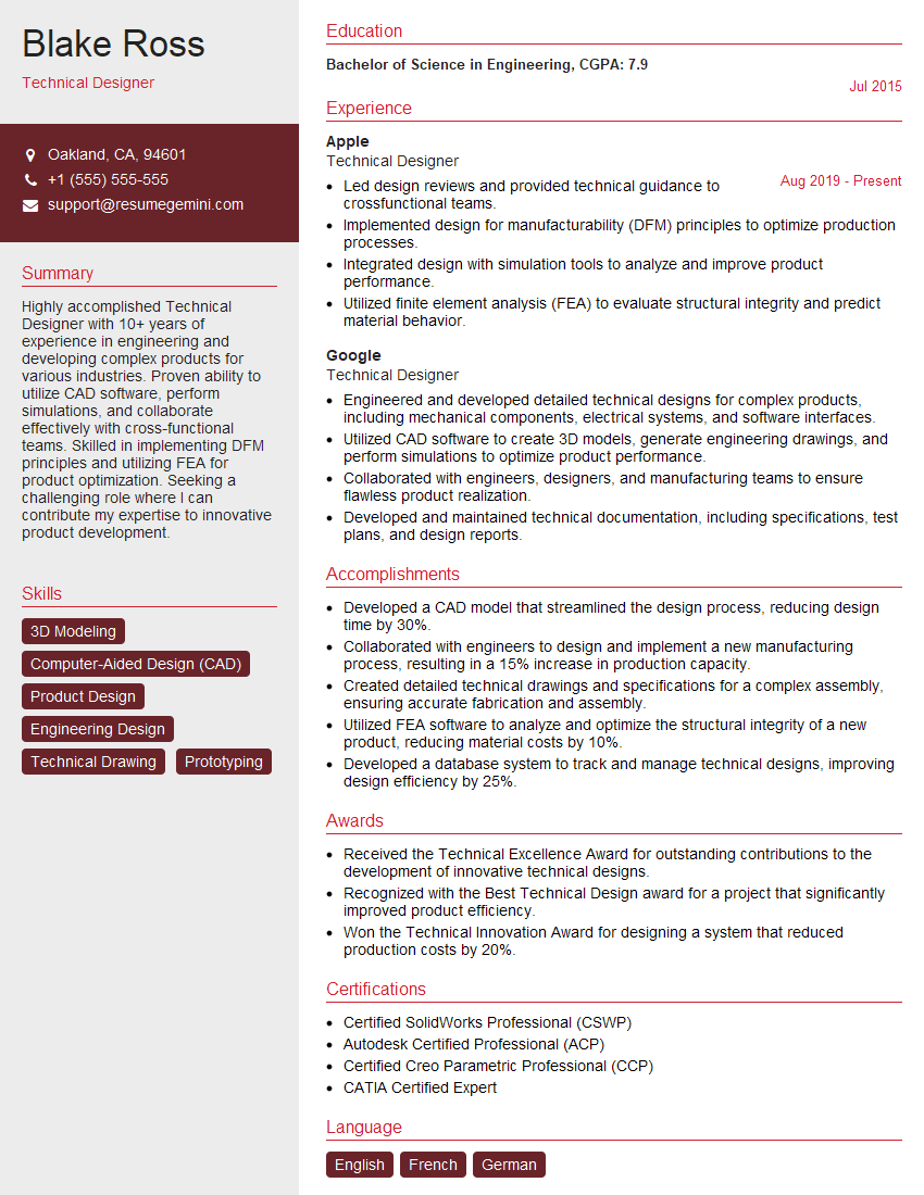
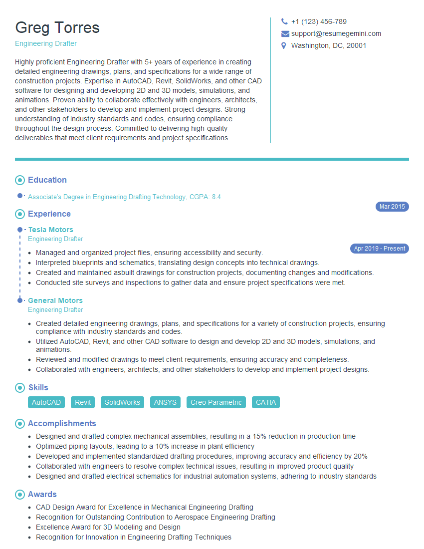
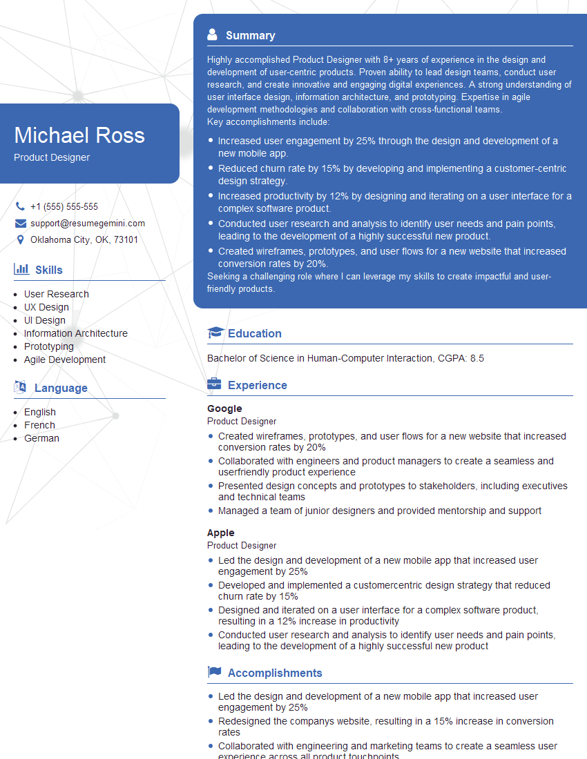
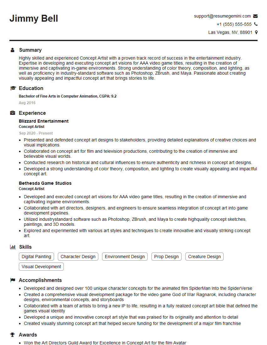
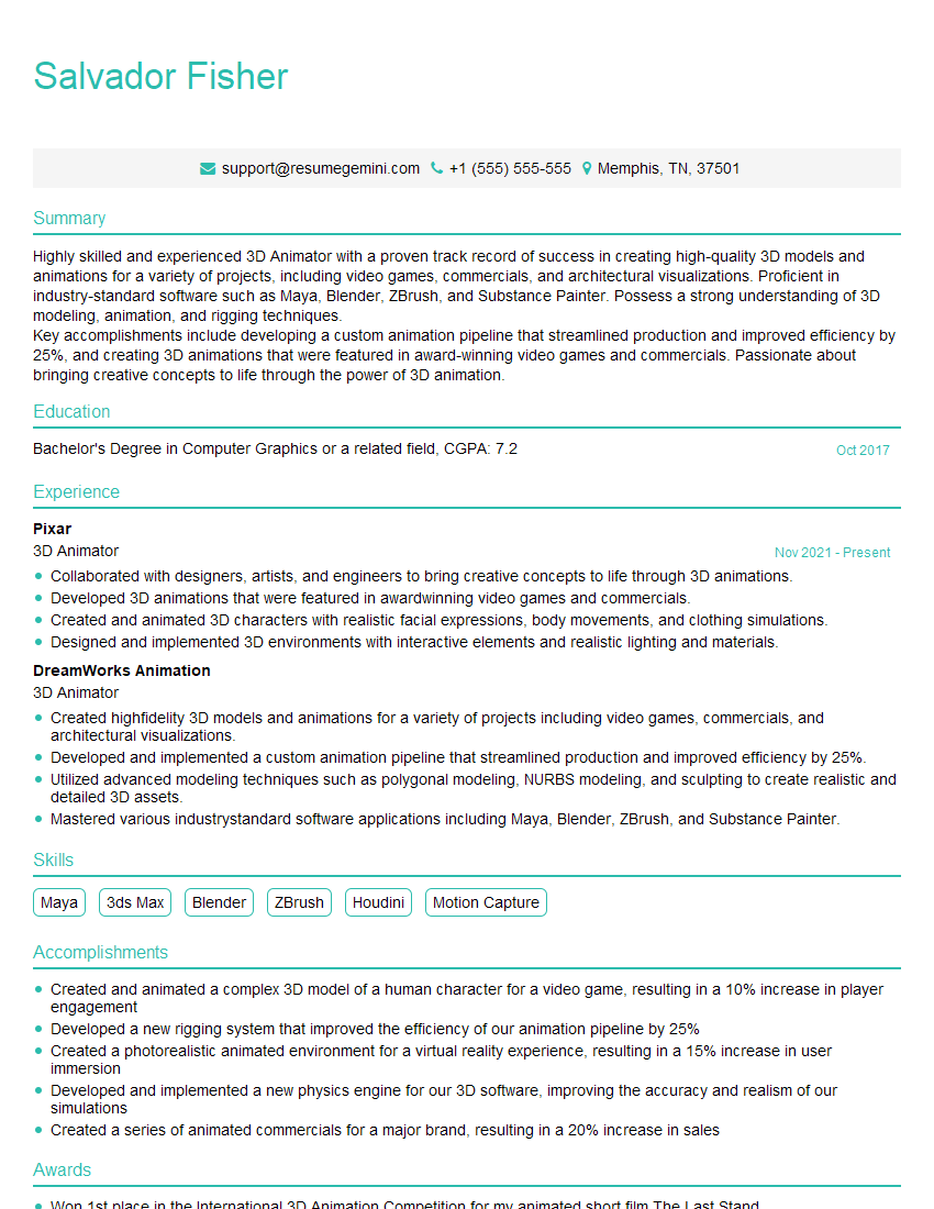
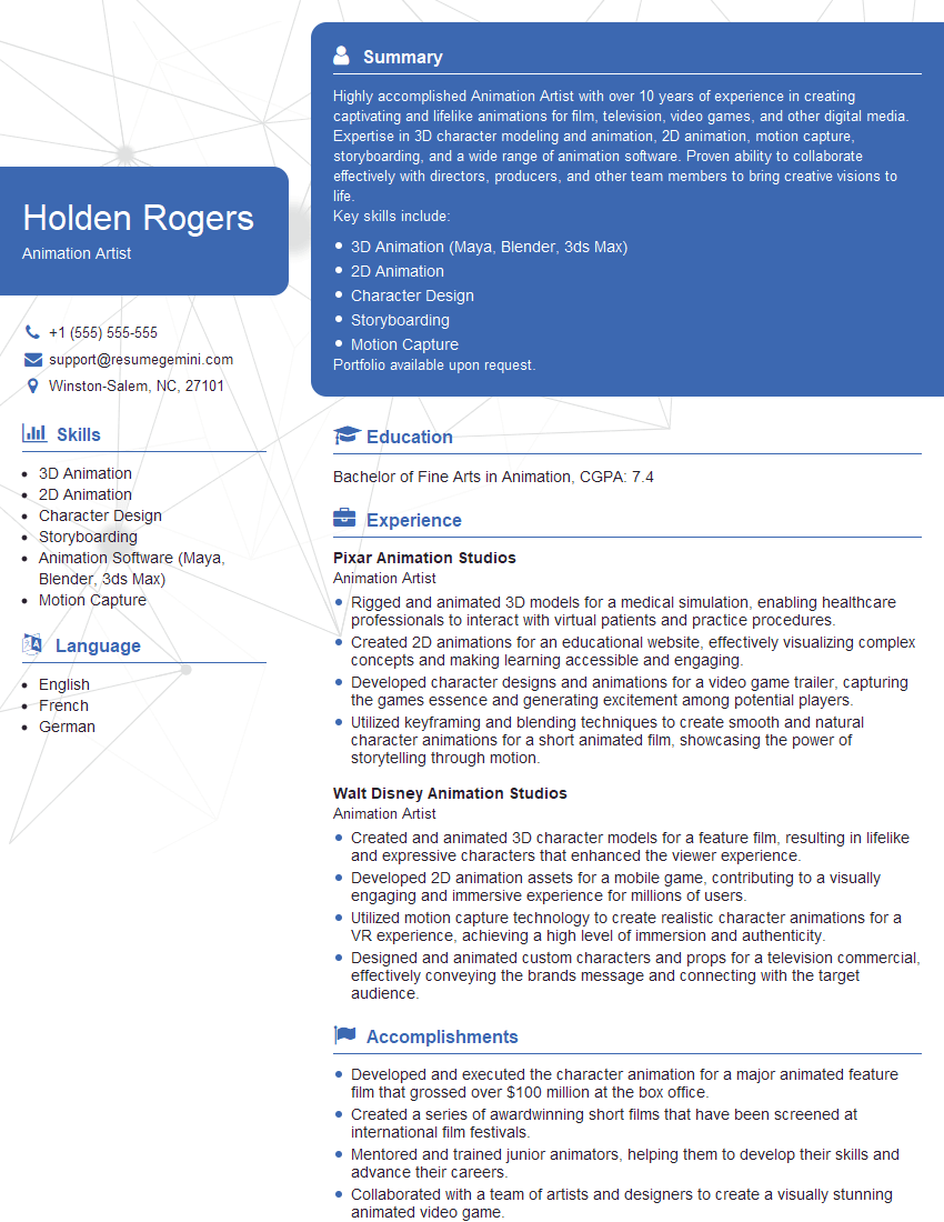
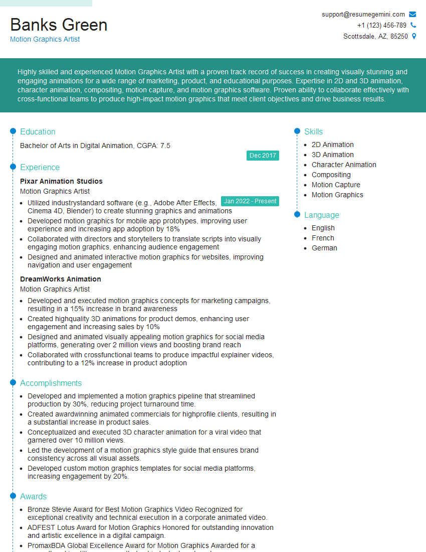
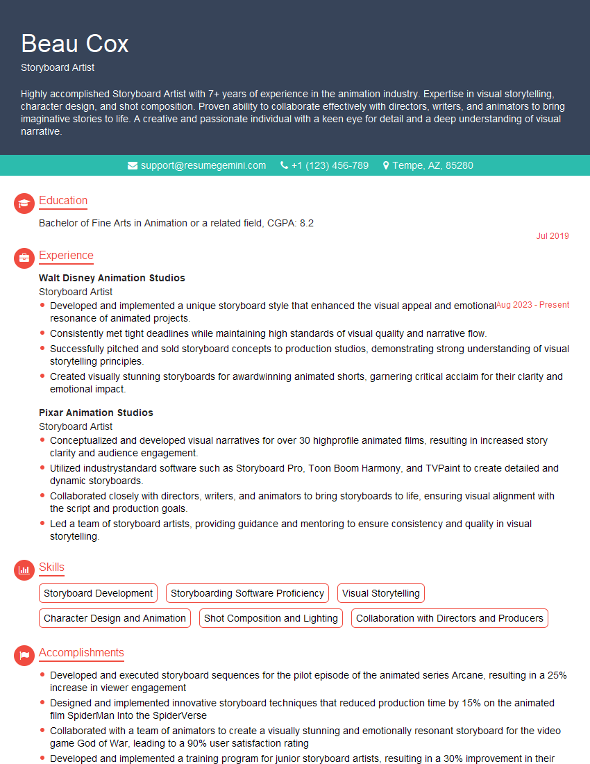
Mastering 2D and 3D sketching is crucial for a successful career in design, architecture, engineering, or related fields. Strong sketching skills demonstrate your spatial reasoning abilities, design thinking, and communication skills—highly valued attributes in many industries. To maximize your job prospects, crafting a compelling and ATS-friendly resume is essential. ResumeGemini is a trusted resource to help you build a professional resume that highlights your skills effectively. We offer examples of resumes tailored to 2D and 3D sketching professionals to help guide you.
Explore more articles
Users Rating of Our Blogs
Share Your Experience
We value your feedback! Please rate our content and share your thoughts (optional).

