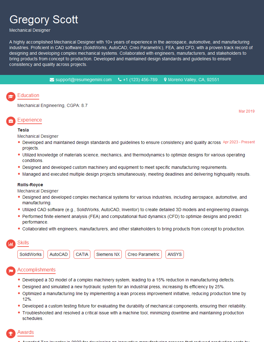
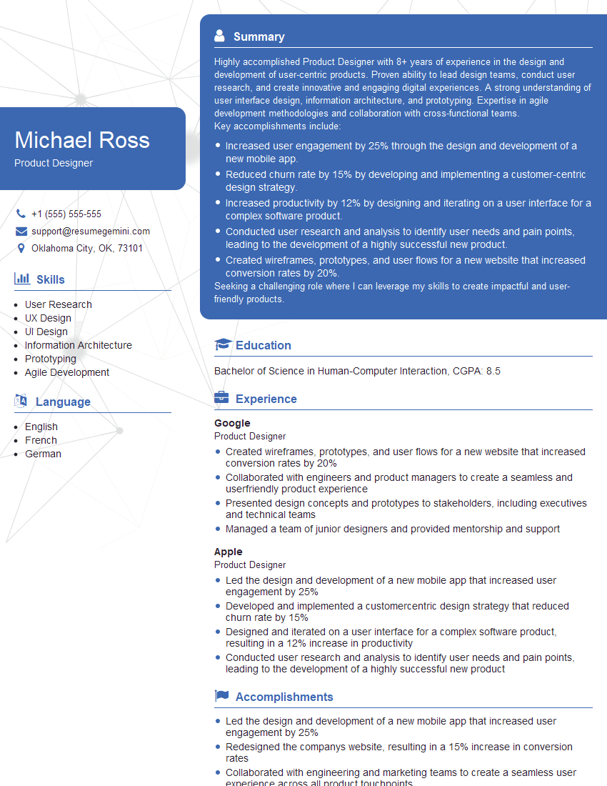
Unlock your full potential by mastering the most common 2D and 3D CAD Software Proficiency interview questions. This blog offers a deep dive into the critical topics, ensuring you’re not only prepared to answer but to excel. With these insights, you’ll approach your interview with clarity and confidence.
Questions Asked in 2D and 3D CAD Software Proficiency Interview
Q 1. Explain the difference between 2D and 3D CAD modeling.
The core difference between 2D and 3D CAD modeling lies in the dimensionality of the designs. 2D CAD software creates flat, two-dimensional drawings, like blueprints for a house or technical drawings for a machine part. Think of it like drawing on a piece of paper – you have length and width, but no depth. 3D CAD software, on the other hand, allows you to create three-dimensional models that represent objects in the real world, complete with length, width, and depth. This allows for a much more realistic and comprehensive representation of a design.
Imagine designing a simple chair. In 2D, you’d draw separate views – front, side, top – each showing only two dimensions. In 3D, you build a complete virtual model of the chair that you can rotate, view from any angle, and even perform simulations on. This leads to a much better understanding of the design’s form, functionality, and potential for manufacturing.
Q 2. Describe your experience with AutoCAD.
I have extensive experience with AutoCAD, spanning over eight years. My proficiency includes 2D drafting, utilizing commands like LINE, CIRCLE, ARC, and POLYLINE to create precise drawings. I’m also adept at creating detailed annotations, dimensioning, and utilizing layers and blocks for efficient organization and reusability. Furthermore, my experience extends to utilizing AutoCAD’s advanced features like 3D modeling with solids and surfaces, parametric constraints, and creating and managing external references (xrefs) for large projects. I’ve used AutoCAD extensively in projects ranging from architectural floor plans and site plans to mechanical part drawings and assembly diagrams, consistently delivering high-quality and accurate outputs.
For example, I once used AutoCAD to design a complex piping system for an industrial plant. By utilizing blocks and parametric constraints, I could easily modify the system’s layout and automatically update dimensions and related components. This significantly reduced the time required for revisions and ensured consistency throughout the design process.
Q 3. What are the advantages of using parametric modeling?
Parametric modeling is a powerful technique that defines design elements through parameters and relationships rather than just fixed geometry. This means that when you change one parameter, the entire model updates automatically, maintaining the defined relationships. This offers significant advantages:
- Design Flexibility: Easy modification without manual adjustments.
- Time Efficiency: Reduces the time spent on repetitive tasks and manual adjustments.
- Error Reduction: Minimizes the chance of inconsistencies arising from manual changes.
- Improved Design Exploration: Enables quick iterations and exploration of design alternatives.
- Better Collaboration: Facilitates easy design sharing and modification among teams.
For instance, imagine designing a gear. A parametric model allows you to specify the number of teeth, module, pressure angle, etc., as parameters. Changing the number of teeth instantly updates the gear’s overall size and geometry, ensuring all related dimensions remain consistent. This contrasts with non-parametric modeling where every change requires manual adjustments.
Q 4. How do you handle large CAD files efficiently?
Handling large CAD files efficiently requires a multi-faceted approach. Firstly, I always strive to use efficient modeling techniques to avoid unnecessary complexity. This includes using appropriate layers, blocks, and referencing external files wherever feasible. Secondly, I utilize the software’s optimization features, such as purging unused data and auditing the file to identify and resolve errors. I also regularly save incremental versions of my work, creating backups and avoiding overwriting previous versions. Lastly, utilizing high-performance computer hardware with ample RAM and a fast processor is critical for smooth performance with large files. For extremely large assemblies, I might consider techniques like model simplification or using smaller sub-assemblies, linked via external references.
In one instance, I worked on a project with a CAD file exceeding 2GB. By systematically purging unused data and employing external references to manage different aspects of the design, I managed to reduce the file size by over 50%, significantly improving performance and workflow.
Q 5. What are your preferred 3D modeling software packages?
My preferred 3D modeling software packages include SolidWorks, Fusion 360, and Rhino. SolidWorks excels in its robust features for creating complex mechanical assemblies and performing simulations, while Fusion 360’s cloud-based nature and integration with other Autodesk products makes it ideal for collaborative projects and rapid prototyping. Rhino, with its NURBS-based modeling, provides exceptional control and precision for organic shapes and freeform design.
The choice of software often depends on the specific project requirements. For a complex mechanical assembly, SolidWorks would be my go-to choice. For a rapid prototype or a project requiring cloud collaboration, Fusion 360 is ideal. And for organic shapes, I’d lean towards Rhino.
Q 6. Describe your experience with SolidWorks or similar software.
My experience with SolidWorks is extensive, encompassing feature-based modeling, assembly design, and simulation. I’m proficient in creating complex parts using features like extrudes, revolves, and sweeps, effectively managing configurations and design tables. I have significant experience in assembly design, utilizing mates and constraints to create realistic and functional assemblies, and have utilized SolidWorks Simulation extensively for stress analysis, motion studies, and finite element analysis (FEA).
For example, I used SolidWorks to design and simulate a robotic arm. By creating a detailed assembly with all necessary components and using simulation tools, I verified the functionality and structural integrity of the design before physical prototyping.
Q 7. How do you ensure accuracy and precision in your CAD work?
Ensuring accuracy and precision in CAD work is paramount. My approach involves a multi-step process. Firstly, I meticulously define all design parameters and constraints from the outset. I use precise measurements and tolerances throughout the design process, relying heavily on the software’s dimensioning tools. Regularly checking my work against design specifications and using verification tools are crucial. Lastly, I rigorously test and validate my designs, often through simulations or prototyping, to ensure they meet all performance requirements. Additionally, I adhere to strict naming conventions and organizational strategies within the software to avoid errors and ensure consistency.
For instance, when designing a precision instrument part, I would always use geometric dimensioning and tolerancing (GD&T) standards to specify the allowable variations in dimensions, ensuring that the manufactured part will meet the required specifications.
Q 8. Explain the process of creating technical drawings.
Creating technical drawings involves a systematic process that ensures clarity, accuracy, and adherence to industry standards. It begins with a clear understanding of the design’s purpose and specifications. This includes gathering information about dimensions, materials, tolerances, and any relevant annotations.
The process typically follows these steps:
- Conceptualization and Planning: Sketching initial ideas and defining the scope of the drawing.
- Software Selection: Choosing the appropriate CAD software (AutoCAD, SolidWorks, Inventor, etc.) based on project complexity and requirements.
- Drawing Creation: Utilizing CAD tools to create the 2D or 3D model, incorporating accurate dimensions, annotations (like notes, tolerances, and surface finishes), and appropriate views (orthographic projections, isometric views, section views).
- Dimensioning and Tolerancing: Applying precise dimensions and tolerances following established standards (e.g., ASME Y14.5).
- Annotation and Detailing: Adding necessary information, including material specifications, surface treatments, and manufacturing instructions.
- Review and Revision: Thoroughly checking for errors and inconsistencies before finalizing the drawing. This often involves peer review and collaboration.
- Output and Distribution: Generating the drawing in the desired format (PDF, DWG, DXF) for printing, sharing, or manufacturing purposes.
For example, designing a simple bracket might involve creating orthographic views (front, top, side), adding dimensions to each view, specifying the material (e.g., steel), and indicating the required surface finish. More complex projects, like a car engine, would involve hundreds of detailed drawings and assemblies.
Q 9. How do you manage revisions and version control in CAD projects?
Managing revisions and version control is crucial in CAD projects to maintain accuracy, track changes, and avoid confusion. This is typically achieved through the software’s built-in revision control features or by integrating with a dedicated version control system (like Git).
Common strategies include:
- Revision Numbers/Designators: Assigning unique revision numbers (e.g., Rev. A, Rev. B) to each iteration of the drawing, clearly indicating the changes made in each revision.
- Revision Tables: Creating a table within the drawing that documents each revision, including the date, author, and description of changes.
- Version Control Systems: Using a dedicated system like Git to manage different versions of the CAD file, enabling rollback to previous versions if necessary and facilitating collaborative work.
- Cloud-Based Storage: Utilizing cloud-based storage solutions (e.g., Autodesk A360, Dropbox) to centralize project files and enable easy access for team members.
- Check-in/Check-out Systems: Implementing a system where only one person can modify the file at a time, preventing conflicts and ensuring data integrity.
Imagine a team working on a complex machine. Version control ensures everyone works with the most up-to-date drawing, preventing costly errors from outdated information.
Q 10. What are some common CAD file formats and their applications?
Several common CAD file formats exist, each serving different purposes. The choice depends on the software used, intended application, and data exchange requirements.
- DWG (Drawing): Autodesk’s native format, widely used for 2D and 3D CAD data. It’s highly versatile and supports complex design information.
- DXF (Drawing Exchange Format): A more open, non-proprietary format facilitating data exchange between different CAD software packages. It’s simpler than DWG but might lose some information during conversion.
- STEP (Standard for the Exchange of Product model data): A neutral, industry-standard format for exchanging 3D CAD models. It ensures data integrity and compatibility across various software platforms.
- IGES (Initial Graphics Exchange Specification): Similar to STEP, IGES is a neutral format for exchanging 3D CAD models, though it’s becoming less prevalent compared to STEP.
- STL (Stereolithography): Commonly used for 3D printing. It represents the model as a mesh of triangles, suitable for rapid prototyping and manufacturing.
- PDF (Portable Document Format): A widely used format for distributing and sharing final drawings, offering great compatibility across platforms but losing the editing capabilities of the original CAD file.
For instance, a client might request drawings in PDF for review, while the engineering team uses DWG for design modifications. A manufacturing facility could receive data in STEP for production planning.
Q 11. Describe your experience with CAD rendering techniques.
CAD rendering techniques transform wireframe models into visually appealing and realistic images, aiding in visualization, communication, and marketing. My experience encompasses various rendering methods:
- Ray Tracing: Simulates the way light interacts with objects, creating highly realistic images with accurate reflections and shadows. It’s computationally intensive but yields superior results.
- Rasterization: A faster method that renders images pixel by pixel, suitable for real-time visualization and interactive manipulation. While less realistic than ray tracing, it’s efficient for animations and interactive simulations.
- Path Tracing: A more advanced form of ray tracing that considers light bouncing multiple times, leading to even more realistic results.
- Global Illumination: Accounts for indirect lighting, enhancing realism by simulating light bouncing off surfaces.
- Photorealistic Rendering: Aims to create images indistinguishable from photographs, often involving advanced techniques like subsurface scattering and physically based rendering (PBR).
In a project involving a new product design, I used ray tracing to generate high-quality images for marketing brochures. For interactive presentations, I opted for rasterization to ensure smooth and lag-free animations.
Q 12. How do you create and modify 3D models in your preferred software?
My preferred 3D CAD software is SolidWorks, though I am proficient in other packages like Autodesk Inventor. Creating and modifying 3D models in SolidWorks involves a combination of features and techniques:
- Extrusion: Creating 3D shapes by extending a 2D profile along a path.
- Revolve: Generating shapes by rotating a 2D profile around an axis.
- Sweep: Creating 3D shapes by sweeping a profile along a path.
- Loft: Forming complex shapes by interpolating between multiple cross-sections.
- Boolean Operations: Combining or subtracting 3D shapes (union, subtraction, intersection).
- Feature-Based Modeling: Building models by adding or modifying features (extrusions, cuts, holes, etc.), making it easy to change the design iteratively.
- Parametric Modeling: Defining relationships between design elements, so changing one parameter automatically updates related parts. This is vital for design optimization and iterative changes.
For example, designing a complex part like a gear would involve using extrusion to create the gear teeth and then using revolve to create the overall cylindrical shape. Boolean operations can be used to create complex features by subtracting one shape from another.
Q 13. How do you manage layers and blocks effectively in CAD?
Effective layer and block management is essential for organizing complex CAD drawings and promoting efficiency. Layers allow for separating different aspects of the design (e.g., structural elements, electrical components, annotations), while blocks enable creating reusable components.
- Layer Organization: Using a logical naming convention (e.g., layer names indicating their purpose) and color-coding layers for easy identification.
- Layer Visibility Control: Turning layers on or off to focus on specific aspects of the design without cluttering the workspace.
- Layer Locking: Preventing accidental modification of certain layers.
- Block Creation: Creating blocks of frequently used components (e.g., standard bolts, screws, symbols) to avoid repetitive drawing and ensuring consistency.
- Block Attributes: Defining attributes within blocks (e.g., part number, material) to easily manage and update information associated with the block instance.
- Block Libraries: Building and maintaining libraries of reusable blocks for future projects, enhancing efficiency and standardization.
In a large-scale project like a building blueprint, layers would be used to separate architectural elements, structural elements, MEP (mechanical, electrical, plumbing), and landscaping. Reusable blocks, like doors and windows, would simplify the design process and ensure consistent representation.
Q 14. Explain your experience with creating assemblies and parts in 3D CAD.
Creating assemblies and parts in 3D CAD is fundamental to designing complex products. SolidWorks, for instance, provides tools for efficient assembly and part management:
- Part Modeling: Creating individual components (parts) with precise geometry and features.
- Assembly Creation: Combining individual parts to form an assembly, defining constraints and relationships between parts.
- Constraints: Defining how parts interact within an assembly (e.g., fixed, mate, concentric). These constraints ensure proper assembly and prevent unintended movement.
- Assembly Features: Adding features to the assembly, such as weldments, patterns, or other assembly-level elements.
- Exploded Views: Creating visually appealing exploded views for documentation and presentation.
- Motion Simulation: Simulating the movement and interaction of parts within an assembly to verify functionality.
- Component Management: Utilizing SolidWorks’ component management tools to effectively organize and manage large assemblies with numerous parts.
For example, designing a bicycle involves creating individual parts like the frame, wheels, handlebars, and then assembling them in SolidWorks, defining constraints to ensure they connect properly and move as expected. Motion simulation could be used to analyze the movement of the chain and pedals.
Q 15. How do you troubleshoot and resolve common CAD issues?
Troubleshooting CAD issues is a crucial skill. My approach involves a systematic process starting with identifying the issue’s nature. This often involves checking the software’s error logs, examining the model’s history, and confirming the integrity of the files.
- Software-Related Issues: These can range from simple glitches to corrupted files. I’ll start by restarting the software, checking for updates, and ensuring sufficient system resources (RAM, disk space). If the issue persists, a software reinstall might be necessary.
- Model-Related Issues: Problems like unexpected geometry or rendering errors frequently stem from flawed modeling practices. I meticulously review the model’s construction history, paying close attention to potentially problematic commands or operations. Sometimes, a simple undo or redo can solve the problem. In more complex cases, I might need to rebuild sections of the model.
- Hardware-Related Issues: Sufficient RAM, a powerful graphics card, and a fast processor are vital for smooth CAD performance. Slowdowns or crashes can point to hardware limitations. I’d check system specs and consider upgrading if necessary.
- File Corruption: This is a serious issue that can require recovery tools. I’m proficient in using recovery utilities and backups to restore corrupted files. Preventive measures, like regular saving and version control, are critical.
For example, I once encountered a rendering error in a complex assembly. By meticulously reviewing the model’s history and isolating specific components, I identified a faulty constraint that was causing the problem. Removing and reapplying the constraint fixed the rendering error.
Career Expert Tips:
- Ace those interviews! Prepare effectively by reviewing the Top 50 Most Common Interview Questions on ResumeGemini.
- Navigate your job search with confidence! Explore a wide range of Career Tips on ResumeGemini. Learn about common challenges and recommendations to overcome them.
- Craft the perfect resume! Master the Art of Resume Writing with ResumeGemini’s guide. Showcase your unique qualifications and achievements effectively.
- Don’t miss out on holiday savings! Build your dream resume with ResumeGemini’s ATS optimized templates.
Q 16. Describe your experience using CAD for design and manufacturing applications.
I have extensive experience using CAD software in both design and manufacturing. In a previous role, I utilized SolidWorks to design a new line of injection-molded plastic components for a medical device. This involved creating 3D models, generating 2D drawings for manufacturing, and performing tolerance analysis to ensure manufacturability.
For a different project, I used Autodesk Inventor to design a complex assembly for an industrial robot arm. This involved creating detailed assemblies, simulations for movement analysis, and the generation of detailed manufacturing documentation. My experience spans various industries including automotive, medical devices, and consumer products. I’m comfortable working with both parametric and direct modeling techniques and am adept at optimizing designs for manufacturing efficiency.
I’ve also used CAD software for creating architectural designs, including floor plans and building elevations, demonstrating my adaptability across different domains. The key here is understanding the specific requirements and constraints of each application to create effective and efficient designs.
Q 17. How familiar are you with CAM software and its integration with CAD?
I possess significant familiarity with CAM (Computer-Aided Manufacturing) software and its seamless integration with CAD. My experience primarily involves using Mastercam and Fusion 360. I understand the importance of creating CAD models that are optimized for manufacturing processes. This includes consideration of factors such as toolpath generation, material selection, and machining tolerances.
The integration between CAD and CAM is crucial for efficient manufacturing. The CAD model provides the geometrical information needed by the CAM software to generate the toolpaths for CNC machining. I understand the importance of proper model preparation, including creating solid models, defining manufacturing features, and ensuring that the model is free of errors before importing it into CAM software. I’m proficient in generating various types of toolpaths, including milling, turning, and drilling operations. Understanding the limitations and capabilities of different machining processes allows me to create efficient and effective manufacturing plans.
For example, in a previous project, I used SolidWorks to design a part, then imported it into Mastercam to generate toolpaths for a 5-axis milling machine. This process involved selecting appropriate cutting tools, optimizing cutting parameters, and simulating the machining process to identify and resolve potential collisions before actual machining.
Q 18. Describe your experience with creating detailed engineering drawings.
Creating detailed engineering drawings is a cornerstone of my CAD expertise. I follow established standards (such as ANSI or ISO) to ensure clarity, precision, and consistency. My drawings include all necessary views, sections, details, dimensions, tolerances, and material specifications.
I understand the importance of creating clear and unambiguous annotations, using appropriate callouts, and generating detailed parts lists. I’m proficient in using various drafting tools and techniques to create professional-looking drawings that are easily understood by manufacturers and other stakeholders. This includes creating dimensioned drawings, creating detailed assembly drawings, and creating fabrication drawings.
For instance, in one project, I created a comprehensive set of drawings for a complex mechanical assembly. These included individual part drawings, assembly drawings showing the relationships between components, and detailed exploded views to aid in assembly. The drawings were reviewed and approved by manufacturing engineers, ensuring that the design was manufacturable and met all required specifications.
Q 19. What are the differences between wireframe, surface, and solid modeling?
The three primary modeling techniques in CAD – wireframe, surface, and solid modeling – represent different levels of geometric complexity and detail. Each has specific applications and limitations:
- Wireframe Modeling: This is the simplest form, representing the object using only lines and curves defining its edges. It’s useful for initial sketching and conceptual design but lacks information about the object’s surface or volume. Think of a simple line drawing of a cube – you see the edges, but not the faces or the interior.
- Surface Modeling: This technique builds upon wireframes by defining surfaces. It’s suitable for creating complex shapes with smooth curves and aesthetics but doesn’t inherently define the object’s volume. It’s commonly used in automotive and product design for creating visually appealing shapes.
- Solid Modeling: This is the most comprehensive approach, defining the object’s complete geometry, including its volume and material properties. It’s crucial for engineering design as it allows for accurate mass property calculations, finite element analysis (FEA), and manufacturing process planning. Think of a digital replica – it has the volume, surface, and every physical characteristic.
Choosing the right modeling technique depends heavily on the application. For example, wireframe modeling might suffice for a preliminary design review, while solid modeling is essential for detailed engineering design and manufacturing.
Q 20. How do you create and apply constraints in parametric modeling?
Parametric modeling is a powerful technique that allows for creating and manipulating designs based on parameters and constraints. Constraints define relationships between geometric elements (points, lines, surfaces), ensuring that the model remains consistent and predictable as parameters are changed.
Creating constraints typically involves selecting geometric entities and applying relationships, such as:
- Geometric Constraints: These define spatial relationships such as parallelism, perpendicularity, tangency, concentricity, and coincidence.
- Dimensional Constraints: These specify distances, angles, and radii between elements.
- Mathematical Constraints: These define complex relationships using equations or formulas.
For example, to create a rectangular part, I’d start by defining two points. Then, I’d apply constraints to define the length and width, perhaps by specifying distances between points or enforcing perpendicularity between lines. Applying a constraint such as ‘parallel’ ensures lines remain parallel regardless of changes to other dimensions. Changing one parameter, say the length, would automatically update other dimensions to maintain the defined relationships. This makes design modification much easier and ensures consistency.
Q 21. How do you use CAD to collaborate with other team members?
Collaboration is essential in modern engineering. I utilize various methods to effectively share CAD models and designs with team members:
- Cloud-Based Collaboration Platforms: I use platforms like Autodesk A360, SharePoint, or similar services to store and share CAD files, allowing multiple users to access and work on the same project simultaneously. Version control is essential here to track changes and avoid conflicts.
- Data Management Systems (PDMS): For large-scale projects, a PDM system is crucial for managing versions, revisions, and metadata associated with each design file.
- Design Reviews and Markups: I actively participate in design reviews, both in-person and remotely. I utilize markup tools within the CAD software or external tools to annotate and comment on designs, fostering effective feedback and collaboration. This ensures a shared understanding of the design intent.
- Standard File Formats: Sharing models using standard formats (STEP, IGES, etc.) ensures compatibility between different CAD software packages used by various team members.
For instance, on a recent project, our team used a cloud-based platform to share CAD models, allowing engineers in different locations to access and modify the design simultaneously. Using version control ensured everyone had access to the latest updates while allowing them to work independently without overriding each other’s changes. This streamlined the design process significantly.
Q 22. Describe your experience with CAD standards and best practices.
CAD standards and best practices are crucial for ensuring design consistency, interoperability, and manufacturability. My experience encompasses adhering to industry standards like ISO, ASME Y14.5 (for GD&T), and company-specific standards. This includes proper file naming conventions, layer management, and utilizing templates to maintain a structured workflow.
For example, I consistently employ a layered approach in my designs, separating geometry by function (e.g., mechanical parts, electrical components). This improves organization, making revisions and collaboration smoother. I also strictly follow the chosen unit system (e.g., millimeters) throughout the project to prevent errors. Furthermore, I utilize design reviews and version control to track changes and ensure compliance with company and industry best practices.
- File Naming: Project Name_Part Name_Revision Number (e.g., Engine_Piston_RevA.sldprt)
- Layer Management: Logical grouping of design elements for easier selection and modification.
- Templates: Pre-configured files containing standard settings, layers, and views to streamline new project setup.
Q 23. How do you perform geometric dimensioning and tolerancing (GD&T)?
Geometric Dimensioning and Tolerancing (GD&T) is essential for communicating precise manufacturing requirements. I use CAD software to define dimensions, tolerances, and geometric controls directly on the model. This involves using symbols and annotations that specify allowable variations in size, form, orientation, location, and runout.
For instance, I’d utilize a position tolerance symbol to define the allowable deviation of a hole’s center from its nominal location. Similarly, I’d employ a circularity tolerance to specify the maximum allowable deviation of a cylindrical feature from perfect roundness. The software then helps visualize these tolerances, flagging potential issues during design. It’s critical to understand the impact of tolerances on assembly and functionality – a seemingly small tolerance can have significant consequences if not managed correctly. I’ve personally used this to troubleshoot design issues in the past and ensure optimal fit and function. I’m proficient with both the ASME Y14.5 and ISO standards.
Example: A position tolerance of ±0.1mm would be represented in the CAD model with a symbol indicating the position and the tolerance value.Q 24. How do you use CAD software to analyze the performance of a design?
CAD software offers several tools for design analysis. I leverage these to evaluate various aspects of a design before manufacturing. Finite Element Analysis (FEA) is frequently used to simulate stress, strain, and displacement under various loading conditions. I’ve used this to optimize structural components, ensuring they can withstand expected forces without failure.
Computational Fluid Dynamics (CFD) can analyze fluid flow characteristics in designs. This is particularly useful in designing systems involving liquids or gases, like ventilation systems or automotive cooling systems. Furthermore, many CAD packages incorporate simulation tools for kinematics and dynamics, enabling the analysis of moving parts and assemblies. This ensures proper functionality and avoids potential interference issues.
For example, I once used FEA to optimize the design of a robotic arm, identifying stress concentration areas and modifying the geometry to improve strength and durability without adding unnecessary weight. The results directly influenced the final design, improving both performance and cost-effectiveness.
Q 25. What are some common design considerations for manufacturability?
Manufacturability is a key consideration throughout the design process. This involves understanding how a design will be made and optimizing it for efficient and cost-effective production.
- Material Selection: Choosing appropriate materials that are readily available, cost-effective, and suitable for the intended application and manufacturing process (e.g., injection molding, casting, machining).
- Simplification of Geometry: Avoiding complex shapes and features that are difficult or expensive to manufacture. For instance, replacing undercuts with draft angles.
- Tolerance Analysis: Defining realistic tolerances to balance precision with manufacturing feasibility and cost. Overly tight tolerances can drive up production costs.
- Assembly Considerations: Designing parts for easy assembly, minimizing the number of components, and ensuring proper clearances.
- Standard Parts: Using commercially available standard parts (e.g., fasteners, bearings) whenever possible to reduce costs and lead times.
Ignoring manufacturability can lead to delays, increased costs, and even design failure. For instance, a design with intricate undercuts might require costly specialized tooling or be altogether impossible to manufacture using conventional methods. Therefore, careful consideration from the initial design stages is paramount.
Q 26. Describe your experience in creating animations or simulations using CAD.
I’ve created animations and simulations using CAD software to convey design concepts, demonstrate functionality, and detect potential design flaws. Software packages such as SolidWorks and Autodesk Inventor offer built-in animation and simulation capabilities.
For example, I’ve used animation to show the movement of a robotic arm in an assembly line, highlighting its reach and dexterity. Simulations have helped analyze stress levels on engine components during operation, providing valuable data for design improvements. Animations and simulations are powerful tools for client presentations, as they provide a visual and engaging understanding of how a design operates and interacts.
Specific applications included creating walkthrough animations of complex assemblies to demonstrate functionality to clients and utilizing simulation to evaluate the efficiency of a gear system, detecting areas of potential stress or wear and tear.
Q 27. How do you manage your CAD projects, from initial concept to final output?
Managing CAD projects effectively involves a structured approach. It begins with a thorough understanding of project requirements and specifications. This is followed by creating a detailed design plan outlining milestones and deliverables.
I typically utilize version control systems (like Vault or PDM Link) to manage project files and track revisions. This ensures that everyone is working with the most up-to-date version of the design and prevents accidental overwriting. Regular design reviews and communication with team members are essential to address any challenges or ambiguities.
The process concludes with generating detailed manufacturing drawings and documentation, ready for production or fabrication. Throughout the entire lifecycle, meticulous attention to detail, adherence to standards, and proactive problem-solving are crucial for project success. For instance, I employ a phased approach – concept sketching, preliminary 3D modeling, detailed design, simulation, and finally, documentation and manufacturing drawings – to ensure a clear progression and effective management.
Q 28. Explain your experience with reverse engineering using CAD software.
Reverse engineering involves recreating a 3D CAD model from an existing physical object. This often begins with creating a point cloud using 3D scanning technology. The point cloud data is then imported into CAD software and processed to create a surface model.
I’ve used various techniques to achieve this, including feature recognition to identify geometric features within the scanned data and manual modeling to refine the geometry for accuracy. This process requires a keen eye for detail and a strong understanding of CAD software capabilities. Once a complete model is created, it can be analyzed, modified, or used to create new designs.
For example, I once reverse engineered a vintage car part that was no longer available commercially. By scanning the original part, generating a 3D model, and performing analysis, I was able to manufacture a high-quality replacement. This process saves significant time and costs compared to starting from scratch.
Key Topics to Learn for 2D and 3D CAD Software Proficiency Interview
- 2D CAD Fundamentals: Understanding drawing principles, layers, dimensions, constraints, and annotation techniques. Practical application: Creating detailed technical drawings from sketches or specifications.
- 3D CAD Modeling Techniques: Mastering various modeling methods (extrusions, revolutions, sweeps) and understanding the differences between solid, surface, and wireframe modeling. Practical application: Designing complex parts or assemblies for manufacturing.
- Software-Specific Features: Familiarize yourself with the specific features and functionalities of the CAD software you’re proficient in (e.g., Autodesk AutoCAD, SolidWorks, Inventor). Practical application: Demonstrating efficient workflow and advanced tool usage.
- Design for Manufacturing (DFM): Understanding manufacturing processes and their implications on design decisions. Practical application: Creating designs that are manufacturable and cost-effective.
- Data Management and Collaboration: Knowledge of file formats, data sharing, and version control within a CAD environment. Practical application: Working effectively on team projects and managing large datasets.
- Blueprint Reading and Interpretation: Ability to accurately read and interpret technical drawings and specifications. Practical application: Understanding existing designs and making modifications.
- Problem-Solving and Troubleshooting: Demonstrate the ability to diagnose and solve common CAD-related issues. Practical application: Effectively managing unexpected errors during design projects.
- Advanced Techniques (depending on experience): Parametric modeling, simulations (FEA, CFD), rendering and visualization, CAM integration.
Next Steps
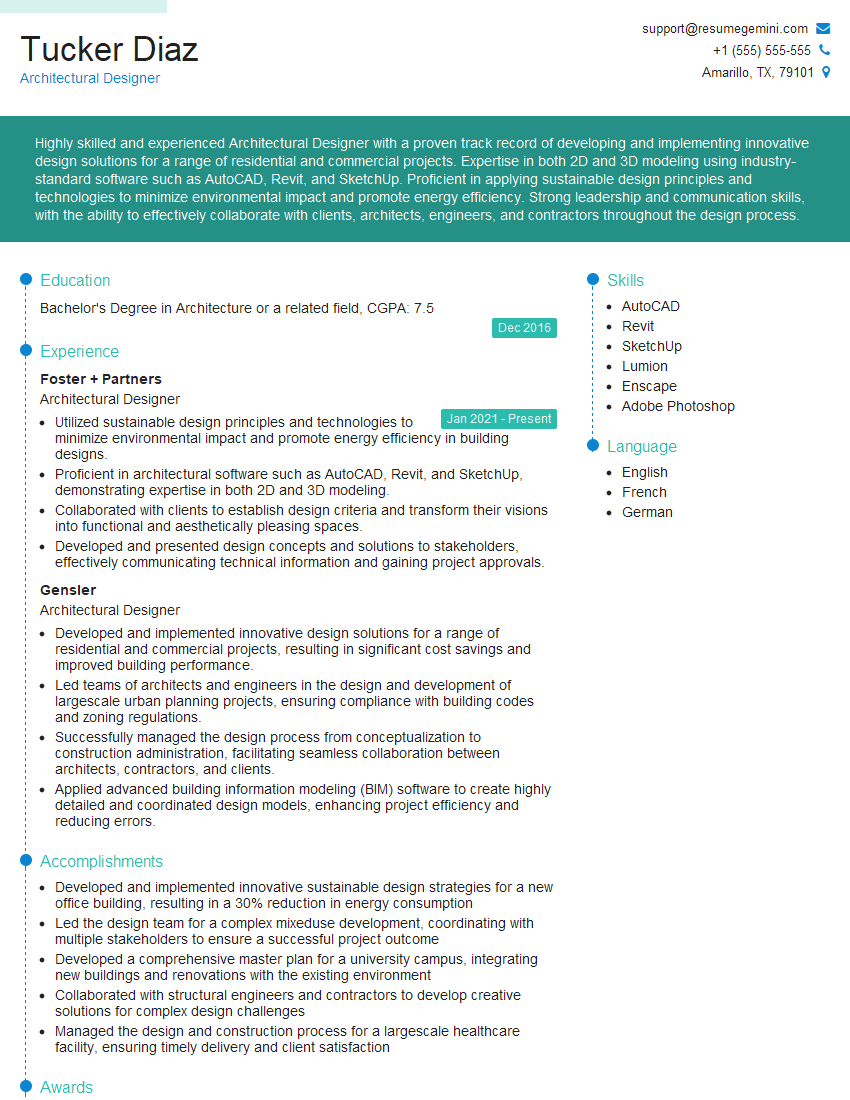
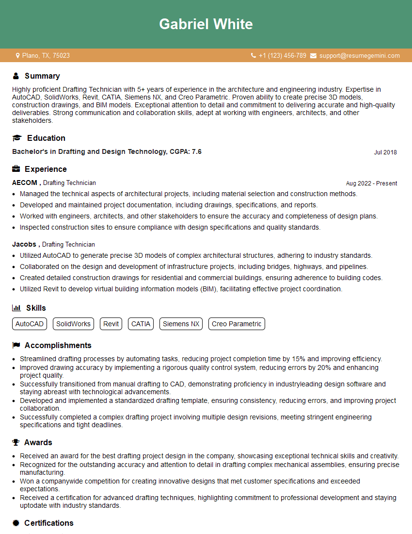
Mastering 2D and 3D CAD software proficiency is crucial for career advancement in engineering, design, and manufacturing. A strong command of these skills opens doors to exciting opportunities and higher earning potential. To significantly boost your job prospects, create an ATS-friendly resume that highlights your skills and experience effectively. ResumeGemini is a trusted resource that can help you build a professional and impactful resume. We provide examples of resumes tailored to 2D and 3D CAD Software Proficiency to guide you in crafting your own compelling application. Invest time in building a strong resume – it’s your first impression on potential employers.
Explore more articles
Users Rating of Our Blogs
Share Your Experience
We value your feedback! Please rate our content and share your thoughts (optional).
What Readers Say About Our Blog
Hello,
We found issues with your domain’s email setup that may be sending your messages to spam or blocking them completely. InboxShield Mini shows you how to fix it in minutes — no tech skills required.
Scan your domain now for details: https://inboxshield-mini.com/
— Adam @ InboxShield Mini
Reply STOP to unsubscribe
Hi, are you owner of interviewgemini.com? What if I told you I could help you find extra time in your schedule, reconnect with leads you didn’t even realize you missed, and bring in more “I want to work with you” conversations, without increasing your ad spend or hiring a full-time employee?
All with a flexible, budget-friendly service that could easily pay for itself. Sounds good?
Would it be nice to jump on a quick 10-minute call so I can show you exactly how we make this work?
Best,
Hapei
Marketing Director
Hey, I know you’re the owner of interviewgemini.com. I’ll be quick.
Fundraising for your business is tough and time-consuming. We make it easier by guaranteeing two private investor meetings each month, for six months. No demos, no pitch events – just direct introductions to active investors matched to your startup.
If youR17;re raising, this could help you build real momentum. Want me to send more info?
Hi, I represent an SEO company that specialises in getting you AI citations and higher rankings on Google. I’d like to offer you a 100% free SEO audit for your website. Would you be interested?
Hi, I represent an SEO company that specialises in getting you AI citations and higher rankings on Google. I’d like to offer you a 100% free SEO audit for your website. Would you be interested?
good

