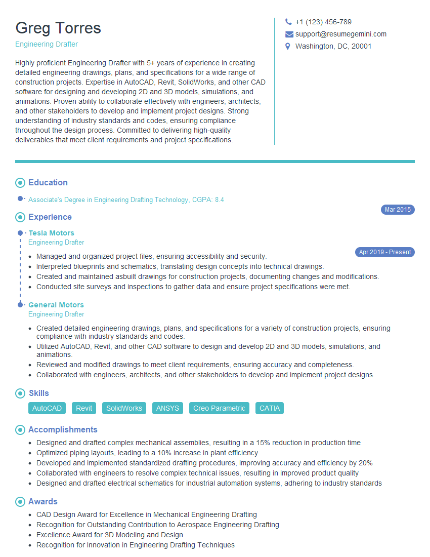
Preparation is the key to success in any interview. In this post, we’ll explore crucial Engineering Drawing Creation interview questions and equip you with strategies to craft impactful answers. Whether you’re a beginner or a pro, these tips will elevate your preparation.
Questions Asked in Engineering Drawing Creation Interview
Q 1. Explain the difference between orthographic and isometric projections.
Orthographic and isometric projections are two fundamental methods for representing three-dimensional objects in two dimensions on a drawing. They differ significantly in their perspective and application.
Orthographic projection uses multiple views (typically top, front, and side) to show the object as if looking directly at each face. Imagine taking pictures of a box from directly above, in front, and from the side. Each picture would only show two dimensions of the box. This method is excellent for precise measurements and detailed representation but can be challenging to visualize the overall 3D shape.
Isometric projection, on the other hand, attempts to represent all three dimensions in a single view. Imagine looking at a corner of the box slightly from above, where all three axes (height, width, and depth) are visible at angles. This gives a more immediate visual understanding of the object’s shape, but precise measurements require careful calculations. Lines are not drawn to true length, and angles are not drawn to their true values.
In short: Orthographic projections are accurate and precise but lack visual immediacy; isometric projections provide a quick visual comprehension but sacrifice precise measurements.
- Orthographic: Ideal for detailed manufacturing drawings, where accuracy is paramount.
- Isometric: Often used for conceptual designs, presentations, and quick visual representations.
Q 2. Describe your experience with different CAD software (e.g., AutoCAD, SolidWorks, Revit).
Throughout my career, I’ve extensively used several CAD software packages, each suited for different tasks and project needs. My proficiency spans from 2D drafting to complex 3D modeling and assembly design.
- AutoCAD: I’ve used AutoCAD extensively for 2D drafting, creating detailed shop drawings, plans, and specifications. Its command-line interface allows for precise control and customization, which is crucial for intricate detail work. I’ve used it extensively in structural and mechanical engineering projects. For example, I once used AutoCAD to create highly detailed drawings for a custom steel staircase, ensuring all measurements and connections were accurate for fabrication.
- SolidWorks: SolidWorks is my go-to for 3D modeling and design. Its intuitive interface and powerful tools have allowed me to create complex assemblies, perform simulations, and generate detailed manufacturing documentation. A project where SolidWorks proved invaluable was designing a new clamping mechanism for an automated assembly line. I leveraged its simulation capabilities to optimize the design for strength and efficiency before manufacturing.
- Revit: My experience with Revit primarily focuses on building information modeling (BIM). I’ve used it for creating detailed architectural and structural models, coordinating with other disciplines, and generating accurate quantity takeoffs. For instance, I recently used Revit to model a complete residential building, including MEP systems, allowing stakeholders to view and interact with the 3D model during the design process.
Q 3. How do you ensure accuracy and precision in your drawings?
Accuracy and precision are paramount in engineering drawings; errors can lead to costly mistakes during manufacturing or construction. I employ several strategies to ensure these qualities.
- Using Precise Input Methods: I avoid freehand sketching whenever possible, relying on precise input methods provided by CAD software, such as coordinate entry and geometric constraints. This ensures that dimensions are exactly as specified.
- Regular Checks and Verification: I regularly cross-check dimensions, tolerances, and geometric relationships using the software’s built-in tools and calculations. Additionally, I often use independent verification methods, such as checking against physical models or comparing to established standards.
- Geometric Dimensioning and Tolerancing (GD&T): I utilize GD&T symbols and standards to clearly communicate allowable variations in dimensions and form. This clarifies acceptable manufacturing deviations and prevents misunderstandings.
- Version Control: Proper version control is vital. I use revision control systems to maintain a history of drawing revisions, facilitating easy tracking and comparison of changes and preventing loss of crucial data.
Q 4. What are the standard drawing scales you commonly use?
The choice of drawing scale depends heavily on the project’s size and complexity. I commonly use scales based on industry standards and project requirements. Some frequently used scales include:
- 1:1 (Full Scale): Used for smaller, detailed components where accuracy is critical.
- 1:2, 1:5, 1:10: Frequently used for architectural and mechanical drawings.
- 1:20, 1:50, 1:100: Common for larger projects like site plans and civil engineering drawings.
- Custom Scales: Sometimes, custom scales are necessary to best fit the drawing to the paper size and detail required. For example, a highly detailed circuit board might use a much larger scale (such as 10:1 or even greater) to show the fine components.
It is crucial that the scale is clearly indicated on the drawing to avoid confusion and errors.
Q 5. Explain the importance of dimensioning and tolerancing in engineering drawings.
Dimensioning and tolerancing are crucial aspects of engineering drawings. They communicate the precise sizes and acceptable variations of components to manufacturers.
Dimensioning specifies the exact sizes and locations of features on a part. It uses various lines and symbols (e.g., dimension lines, extension lines, leader lines) to clearly indicate measurements. Inaccurate dimensioning can lead to parts not fitting together correctly.
Tolerancing defines the allowable variations in dimensions. Tolerances account for manufacturing limitations and ensure that parts are within acceptable ranges. Without tolerances, achieving a perfect dimension is often impossible and unrealistic. GD&T (Geometric Dimensioning and Tolerancing) is frequently used to provide even more precise control over form, orientation, location, and runout.
Example: A shaft with a diameter dimensioned as 25 ± 0.1 mm indicates that any shaft between 24.9 mm and 25.1 mm is acceptable. If this tolerance is not included, the manufacturer might produce a shaft with a significantly different diameter rendering the part unusable.
Q 6. How do you handle revisions and updates to existing drawings?
Managing revisions and updates is critical for maintaining accurate and up-to-date documentation. I follow a systematic approach to ensure all changes are properly tracked and communicated.
- Revision Control System: I always employ a revision control system (e.g., within the CAD software or a dedicated version control system like Git). This allows me to track all modifications and revert to previous versions if necessary.
- Revision Clouds and Numbers: I use revision clouds to clearly highlight areas that have been modified. Each revision is assigned a unique number or letter and documented in a revision table, detailing the date, author, and description of the changes.
- Clear Communication: All changes are communicated to stakeholders, ensuring everyone is working from the most up-to-date drawings.
- Controlled Distribution: Access to the drawings is controlled to prevent unauthorized modifications and ensure data integrity.
This structured approach minimizes the risk of errors due to outdated drawings and ensures project consistency.
Q 7. Describe your experience with creating detailed assembly drawings.
Creating detailed assembly drawings is a complex process that requires careful planning and execution. My experience involves various aspects of assembly drawing creation, from initial concept sketches to final detailed documentation.
- Component Modeling: I begin by creating individual 3D models of each component within the assembly using software like SolidWorks. This allows for accurate representation of parts and simplifies assembly design.
- Assembly Modeling: Once the individual components are complete, I assemble them in the CAD software, ensuring proper fit and functionality. This helps identify interference and design issues early in the process.
- Exploded Views: Creating exploded views is essential for showcasing the assembly’s structure and the relationship between different parts. This helps in understanding the assembly sequence and maintenance.
- Bill of Materials (BOM): I generate a detailed BOM, including part numbers, descriptions, quantities, and other relevant information for each component within the assembly.
- Detail Views: When necessary, I generate detailed views of critical components, highlighting intricate features or assembly details that require specific attention.
The final assembly drawing clearly communicates the assembly process, component relationships, and specifications to the manufacturers and assemblers, minimizing ambiguity and errors.
Q 8. How do you manage layers and blocks in your CAD software?
Effective layer and block management is crucial for creating organized and manageable engineering drawings. Think of layers as transparent sheets stacked on top of each other, each containing specific drawing elements. Blocks are reusable components, like a standard bolt or a specific valve, that can be inserted multiple times without redrawing.
In my CAD software (let’s assume AutoCAD for this example), I utilize layers extensively to separate different aspects of the design. For instance, I might have separate layers for:
Architecture: Walls, doors, windowsStructure: Beams, columns, foundationsMEP (Mechanical, Electrical, Plumbing): Pipes, conduits, ductworkAnnotations: Dimensions, text, notes
This layered approach allows me to easily turn layers on or off, change their properties (line weight, color), and isolate specific elements for editing or printing. For example, if I need to focus solely on the plumbing system, I can simply turn off all other layers.
Blocks are equally important for efficiency. I create blocks for frequently used components, standardizing their representation and ensuring consistency across the project. When I need to add a specific valve, I simply insert the pre-made block instead of drawing it from scratch. This saves time, reduces errors, and ensures uniformity throughout the drawing.
Furthermore, I employ a naming convention for both layers and blocks to maintain a clear and logical organizational structure, making it easy for myself and others to understand the drawing’s composition.
Q 9. What are your preferred methods for creating sections and details?
Creating clear and informative sections and details is critical for conveying design intent. Sections reveal the internal structure of an object, while details enlarge critical areas for precise specification. My approach prioritizes clarity and adherence to relevant standards.
For sections, I utilize the section tools built into my CAD software. I carefully select the cutting plane, ensuring it clearly illustrates the desired features. I use appropriate hatching to differentiate materials, and I always label the section view clearly. For example, a section view of a building would clearly show the layers of materials – foundation, walls, roofing, etc., and their respective thicknesses.
Details are similarly created, focusing on critical features. I often use enlarged views to highlight specific connections or tolerances. For example, a detail view might show a weld joint with specific dimensions and tolerances clearly indicated to ensure proper fabrication. I meticulously annotate details with dimensions and notes to eliminate any ambiguity.
I also pay close attention to the presentation of sections and details, maintaining a consistent scale and employing clear, concise labeling. This enhances the readability and overall effectiveness of the drawings.
Q 10. Explain your understanding of geometric dimensioning and tolerancing (GD&T).
Geometric Dimensioning and Tolerancing (GD&T) is a symbolic language used to precisely define the size, form, orientation, location, and runout of features on a part. It goes beyond simple dimensional notations by specifying acceptable variations, minimizing ambiguity and improving manufacturing efficiency. Think of it as a precise roadmap for manufacturing a part.
My understanding encompasses the use of various GD&T symbols, including:
- Size: Basic size and tolerances (e.g., diameter, length)
- Form: Straightness, flatness, circularity, cylindricity
- Orientation: Parallelism, perpendicularity, angularity
- Location: Position, concentricity, symmetry
- Runout: Circular runout, total runout
I understand the importance of applying GD&T correctly to ensure that parts are manufactured to the required specifications. Incorrect application can lead to costly rework or even part failure. I often use GD&T tables within my drawings to summarize the tolerances and specifications for each feature of a component, ensuring all relevant information is centralized and clearly presented.
For example, specifying the position of a hole using GD&T ensures the hole is located within a specific tolerance zone, irrespective of the hole’s diameter, guaranteeing proper assembly even with slight variations in manufacturing.
Q 11. How do you ensure drawings are compliant with relevant standards (e.g., ANSI, ISO)?
Adherence to relevant standards (like ANSI and ISO) is non-negotiable in engineering drawing creation. These standards ensure clarity, consistency, and interoperability across different teams and organizations.
To ensure compliance, I meticulously follow the specified guidelines for:
- Drawing formats: Size, orientation, and sheet layout according to the applicable standard.
- Line weights and styles: Consistent use of line weights to represent different elements of the drawing.
- Dimensioning and tolerancing: Applying GD&T according to the specified standard (ANSI Y14.5 or ISO 1101 for example).
- Title blocks and revision tables: Including all necessary information in the title block, adhering to the format specified in the standard.
- Material specifications: Clearly indicating the material of each component according to standard material designations.
I regularly consult the applicable standard documents to ensure my drawings meet all the requirements. I utilize templates that are already configured to meet those standards, saving time and reducing the risk of errors.
In a project where both ANSI and ISO standards are involved, I clearly specify which standard applies to each section of the drawing to avoid confusion.
Q 12. Describe your experience with creating and using drawing templates.
Drawing templates are indispensable for creating consistent, high-quality drawings. They act as pre-configured frameworks that contain all the necessary settings and elements, like title blocks, border lines, and layer setups, already in place. This saves significant time and effort and ensures uniformity across multiple drawings.
My experience involves creating templates that conform to the specific standards and requirements of our projects. I customize them with company logos, standard layer setups, and pre-defined text styles. For example, I might create separate templates for different types of drawings: one for architectural drawings, another for structural drawings, and so on.
When using a template, I ensure all necessary information is updated, such as project name, revision number, and date. I carefully manage the layers within the template, ensuring they are appropriately named and organized to avoid confusion. This template-driven approach not only enhances efficiency but also contributes significantly to the consistent quality of our drawings.
Q 13. How do you create and manage bill of materials (BOMs)?
Bill of Materials (BOMs) are crucial for specifying all the components required for a project. My approach integrates BOM creation directly within my CAD software, using its built-in features or add-ons to link components in the drawing to the BOM. This ensures that the BOM is always up-to-date and reflects any changes made to the design.
I typically structure my BOMs to include columns for:
Part Number: A unique identifier for each componentDescription: A clear and concise description of the componentQuantity: The number of each component requiredMaterial: The material from which the component is madeManufacturer: The manufacturer of the component (if applicable)Weight: Weight of the component (if necessary)
I use a consistent format and naming convention for part numbers to maintain a clear and organized BOM. This structured approach simplifies material procurement and ensures that all the necessary components are readily available during the manufacturing process. The use of automated linking between components in my CAD drawing and the BOM minimizes the risk of manual data entry errors. Any change in the CAD model automatically updates the BOM – a significant advantage for complex projects.
Q 14. How do you handle conflicting design requirements?
Conflicting design requirements are an inevitable challenge in engineering. My approach to resolving them involves a structured and collaborative process:
- Identify the conflict: Clearly define the conflicting requirements, noting their source and impact.
- Prioritize the requirements: Determine the relative importance of each requirement based on project goals and constraints.
- Explore potential solutions: Brainstorm different approaches to reconcile the conflicting requirements. This could involve design compromises, the use of alternative materials or technologies, or re-evaluating the original requirements.
- Evaluate solutions: Assess the feasibility and trade-offs of each solution, considering factors such as cost, time, and performance.
- Document the decision: Record the chosen solution and its rationale, ensuring that all stakeholders are informed and agree on the resolution.
- Implement and verify: Integrate the chosen solution into the design and verify its effectiveness.
For example, a conflict might arise between minimizing weight and maximizing strength in a structural component. This requires a careful evaluation of different materials and design approaches, potentially involving finite element analysis (FEA) to determine the optimal solution. Open communication and collaboration are crucial throughout the entire process, involving all relevant stakeholders to ensure buy-in and a smooth resolution.
Q 15. What are your strategies for troubleshooting CAD software issues?
Troubleshooting CAD software issues is a crucial skill for any engineering drafter. My strategy involves a systematic approach, starting with the simplest solutions and progressing to more complex ones. First, I’ll check for obvious things like a frozen application, requiring a simple restart. If that doesn’t work, I’ll look at the file itself – is it corrupted? I might try opening it in a different CAD program or a different version of the same software. Sometimes, it’s a problem with the hardware; is my computer running low on RAM or storage space? Is my graphics card working correctly? For more persistent issues, I’ll consult the software’s help documentation, search online forums for solutions related to the specific error message, or reach out to the software’s technical support team.
For instance, I once encountered a situation where a complex assembly wouldn’t render correctly in AutoCAD. After ruling out hardware issues, I discovered a hidden constraint in the model that was causing the conflict. Removing the constraint resolved the problem. This highlights the importance of understanding the underlying structure of your model.
Career Expert Tips:
- Ace those interviews! Prepare effectively by reviewing the Top 50 Most Common Interview Questions on ResumeGemini.
- Navigate your job search with confidence! Explore a wide range of Career Tips on ResumeGemini. Learn about common challenges and recommendations to overcome them.
- Craft the perfect resume! Master the Art of Resume Writing with ResumeGemini’s guide. Showcase your unique qualifications and achievements effectively.
- Don’t miss out on holiday savings! Build your dream resume with ResumeGemini’s ATS optimized templates.
Q 16. Explain your experience working with different drawing formats (e.g., DWG, DXF, PDF).
I have extensive experience working with various drawing formats, including DWG (AutoCAD’s native format), DXF (a more universal, text-based format suitable for exchanging data between different CAD software), and PDF (a widely used format for sharing and archiving drawings). Understanding the nuances of each format is critical. DWG files, for example, retain all the original CAD data, including layers, blocks, and attributes, offering the most flexibility. DXF files are good for compatibility but might lose some formatting details. PDF files are ideal for sharing and viewing but are not editable unless specifically created as editable PDFs.
In practice, I often start projects in DWG, then export to DXF if collaborating with someone using different software. I’ll export to PDF to create a final deliverable for clients or for archival purposes. For instance, on a recent project involving multiple subcontractors, I used DXF files to ensure everyone could access and edit the drawings in their preferred CAD program without data loss.
Q 17. How do you collaborate with other engineers and designers?
Collaboration is key in engineering design. I utilize several methods to work effectively with other engineers and designers. We frequently use cloud-based platforms that allow us to share and edit drawings simultaneously, providing real-time feedback. Version control software helps us manage multiple revisions and prevents conflicts. Regular meetings, both in person and virtual, are important for discussing design changes, addressing challenges, and ensuring everyone is on the same page. Effective communication through email and instant messaging is also vital.
For example, during the design of a large industrial facility, we used a cloud-based platform to share models and drawings. Team members could access and annotate designs in real time. This facilitated quick review cycles and ensured that everyone was informed about design changes.
Q 18. Describe your experience with creating 3D models and their subsequent 2D drawings.
Creating 3D models and deriving 2D drawings is a standard part of my workflow. I’m proficient in using various 3D modeling software packages to create realistic representations of components and assemblies. After creating a 3D model, I utilize the software’s built-in tools to generate 2D orthographic projections, isometric views, and detailed sections. This process ensures that the 2D drawings accurately reflect the 3D design, eliminating any inconsistencies or ambiguity.
In one project, I modeled a complex robotic arm in SolidWorks. The 3D model allowed us to visualize assembly, check for interference, and perform kinematic analysis. From this 3D model, I generated detailed 2D drawings for manufacturing and assembly, ensuring precision and clarity.
Q 19. How do you ensure drawings are clear, concise, and easy to understand?
Creating clear, concise, and understandable drawings is paramount. I follow established drafting standards and best practices, ensuring that all dimensions, tolerances, and annotations are clearly labeled and easily accessible. I use consistent line weights, fonts, and drawing styles to maintain uniformity and visual appeal. Furthermore, I organize the drawings logically, using layers and views effectively to avoid clutter and improve readability. I also add clear titles, revision blocks, and a comprehensive parts list, creating an easily navigable document.
For instance, instead of cluttering a drawing with numerous dimensions, I utilize reference dimensions to reduce visual noise and improve clarity. I use callouts and detailed views to highlight critical features, providing a more focused and comprehensible illustration.
Q 20. What are the different types of line weights and their uses?
Line weights in engineering drawings are crucial for conveying information about the different parts of a design. They represent the thickness of lines and are measured in millimeters or points. Different line weights are assigned to different elements in the drawing to enhance clarity and differentiate between objects. Common uses include:
- Thick lines: Typically used for visible outlines of objects.
- Medium lines: Used for hidden lines, center lines, and section lines.
- Thin lines: Used for dimension lines, extension lines, and leader lines.
- Dashed lines: Used for hidden edges or center lines.
- Dotted lines: Used for phantom lines or parts which are not directly shown.
Proper line weight selection improves the overall readability and understanding of the drawing, preventing confusion and errors during fabrication or construction. For example, using a thick line for visible contours ensures these features are prominent, making manufacturing and assembly easier.
Q 21. Describe your experience with creating and interpreting electrical schematics.
I have experience creating and interpreting electrical schematics, which are diagrams that show the electrical connections in a circuit or system. My experience encompasses understanding various symbols and conventions, creating clear and accurate schematics that comply with relevant standards, and interpreting existing schematics to understand the functionality of electrical systems. I use specialized software like AutoCAD Electrical for creating and managing complex electrical schematics. The ability to generate reports and BOMs (Bill of Materials) from schematics is an essential part of my skill set.
In one project, I was tasked with creating a schematic for a complex control system. I meticulously organized the components, ensuring consistent wiring diagrams and correct symbol usage. The final schematic, compliant with industry standards, allowed electricians to easily understand the system’s wiring and facilitate trouble-free installation and maintenance.
Q 22. How familiar are you with BIM (Building Information Modeling) workflows?
BIM (Building Information Modeling) workflows are incredibly familiar to me. I’ve worked extensively with various BIM software packages, including Revit, ArchiCAD, and Autodesk Navisworks. My experience encompasses the entire BIM lifecycle, from conceptual design and design development to construction documentation and facility management. I understand the importance of collaborative workflows and data management within a BIM environment. For example, in a recent project involving a large-scale hospital complex, I utilized Revit to coordinate MEP (Mechanical, Electrical, and Plumbing) systems with architectural elements, ensuring clash detection and efficient space planning. This involved leveraging BIM’s capabilities for data visualization, analysis, and collaboration among various disciplines.
I’m proficient in using BIM software to create and manage detailed 3D models, produce accurate 2D drawings, and generate schedules and quantities for materials. I also understand how BIM facilitates better communication and coordination amongst project stakeholders, leading to a more streamlined and efficient construction process. Beyond individual software skills, my expertise extends to implementing BIM standards and best practices to ensure data integrity and project success.
Q 23. How do you handle large and complex drawings efficiently?
Managing large and complex drawings efficiently requires a systematic approach. I employ several strategies. First, I utilize efficient CAD software features like xrefs (external references) and layer management to organize drawing components. Think of it like organizing a large filing cabinet: each drawer (layer) contains specific information, and xrefs allow me to link related files without duplicating data. This makes editing and updating far easier and reduces file sizes.
Second, I leverage the power of parametric modeling. This means creating components that can be easily modified and updated by changing parameters rather than manually adjusting every individual element. Imagine designing a staircase: changing the rise and run automatically updates the whole structure, rather than redrawing each step. This speeds up design revisions and minimizes errors. Finally, I rely on efficient data management techniques. This includes using cloud-based storage, version control systems, and clearly organized file structures. This prevents data loss and simplifies collaboration with team members.
Q 24. What are your experience with creating detailed fabrication drawings?
Creating detailed fabrication drawings is a core part of my expertise. I’ve produced drawings for various construction projects, including structural steel, precast concrete, and MEP systems. This involved understanding manufacturing processes and creating drawings with precise dimensions, tolerances, and fabrication notes. For example, I’ve produced shop drawings for steel fabricators, clearly detailing weld types, bolt specifications, and cut lists. I ensure drawings include sufficient detail for efficient manufacturing, including annotations for material specifications, finishes, and any other requirements for fabrication and construction.
My experience also includes working closely with fabricators to address any questions or discrepancies during the fabrication process. This collaborative approach is crucial to ensuring the final product aligns perfectly with the design intent. I regularly use CAD software’s features for annotations, dimensioning, and detailing, ensuring accuracy and clarity of manufacturing instructions.
Q 25. Explain your understanding of different projection methods (e.g., first-angle, third-angle).
Projection methods are fundamental in engineering drawing. First-angle projection and third-angle projection are two common methods used to represent three-dimensional objects on a two-dimensional plane. The key difference lies in how the object’s views are arranged. In first-angle projection, the views are arranged as if the viewer is looking at the object from outside, with the front view at the bottom and other views placed according to their relative positions. The view arrangement is somewhat counter-intuitive for many.
In third-angle projection, the views are arranged as if the viewer is looking at the object from inside, with the front view placed at the top and other views positioned accordingly. This method is more commonly used in the United States and many other countries because it better represents how one would physically see the object. Understanding these methods is essential to accurately interpreting and creating engineering drawings and to ensure there is no ambiguity when working collaboratively on design projects.
Q 26. How do you ensure your drawings are readily manufacturable?
Ensuring drawings are manufacturable requires careful consideration of several factors. First, precise dimensioning and tolerancing are paramount. Dimensions must be clear, unambiguous, and meet industry standards. Tolerances define acceptable variations from the specified dimensions and are essential to prevent issues during fabrication. I always adhere to relevant standards like ISO or ASME to maintain accuracy and consistency.
Second, material specifications must be clearly stated. This includes specifying material types, grades, and finishes. Third, the drawing should include clear instructions for fabrication, including welding details, machining requirements, and assembly procedures. Lastly, I regularly consult with fabricators and manufacturers throughout the design process. This collaborative approach ensures the drawings are practical and manufacturable from the outset and avoids costly rework later in the process.
Q 27. Describe your process for checking drawings for errors before release.
My drawing checking process is rigorous and multi-layered. It begins with a self-check, where I review the drawings meticulously for dimensional accuracy, completeness of information, and compliance with relevant standards. Then, a peer review is conducted. A colleague examines the drawings independently, offering a fresh perspective and identifying potential errors I might have overlooked. This is like having a second set of eyes to catch mistakes.
Finally, before release, a formal check against specifications and client requirements is performed. This ensures the drawings meet all project criteria. We use checklists to ensure thoroughness and consistency. This systematic process is crucial to prevent errors that could lead to delays, rework, and potentially safety hazards on site.
Q 28. Explain your experience with creating and utilizing custom CAD libraries.
I have significant experience creating and utilizing custom CAD libraries. These libraries are essentially collections of reusable components, such as standardized parts, symbols, and details. This saves considerable time and effort by eliminating the need to repeatedly draw the same elements. For example, I’ve created libraries of standard building components like doors, windows, and structural sections, which are parameterized to allow for easy customization. Imagine having a library of pre-designed furniture: you can drag and drop pieces rather than modeling every chair from scratch.
Developing custom libraries requires a well-defined system and naming convention. This ensures easy retrieval and organization of components. Maintaining and updating these libraries is critical to keep them current and consistent with project standards. This organized approach significantly streamlines workflow and ensures design consistency across multiple projects. We regularly review and update these libraries, adding new components as necessary, to maintain efficiency.
Key Topics to Learn for Engineering Drawing Creation Interview
- Orthographic Projection: Understanding first-angle and third-angle projections, creating multi-view drawings, and interpreting sectional views. Practical application: Accurately representing complex 3D objects in 2D for manufacturing.
- Dimensioning and Tolerancing: Mastering geometric dimensioning and tolerancing (GD&T) symbols and their application to ensure precise manufacturing. Practical application: Communicating design intent and acceptable variations to manufacturing teams.
- Isometric and Perspective Drawings: Creating 3D representations for visualization and communication. Practical application: Quickly conveying the overall design and spatial relationships of components.
- CAD Software Proficiency: Demonstrating expertise in industry-standard CAD software (AutoCAD, SolidWorks, etc.) including 2D drafting and 3D modeling. Practical application: Efficiently creating and modifying engineering drawings.
- Drawing Standards and Conventions: Adherence to relevant industry standards (e.g., ANSI, ISO) for clarity and consistency in drawings. Practical application: Creating professional, universally understood drawings.
- Blueprint Reading and Interpretation: Understanding and interpreting existing engineering drawings effectively. Practical application: Collaborating effectively with other engineers and technicians.
- Material Selection and Specifications: Knowledge of common engineering materials and their representation on drawings. Practical application: Ensuring manufacturability and specifying appropriate materials for the design.
- Technical Communication and Documentation: Clearly communicating design intent through detailed annotations and notes. Practical application: Avoiding misinterpretations and improving collaboration.
Next Steps
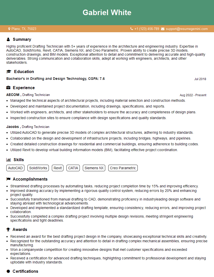
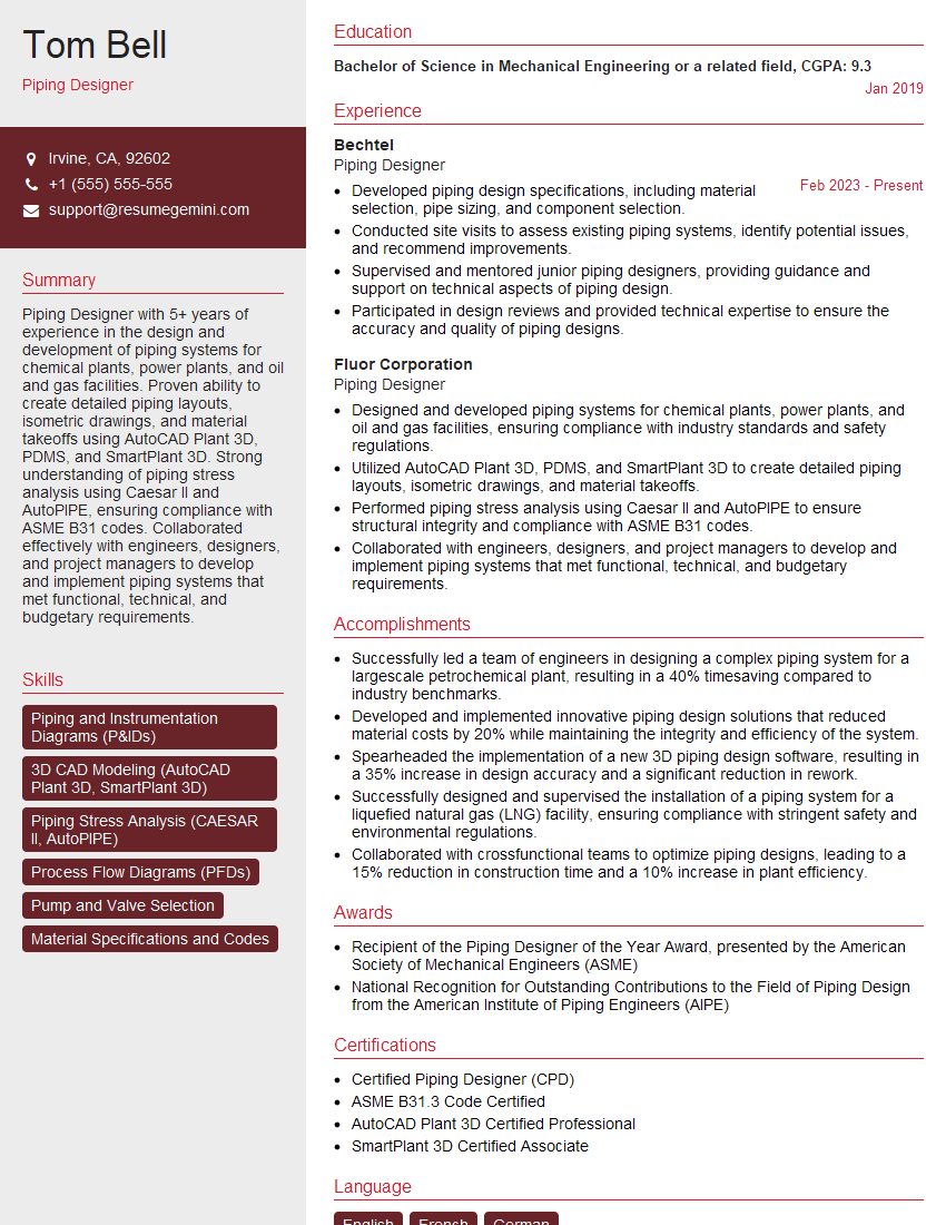
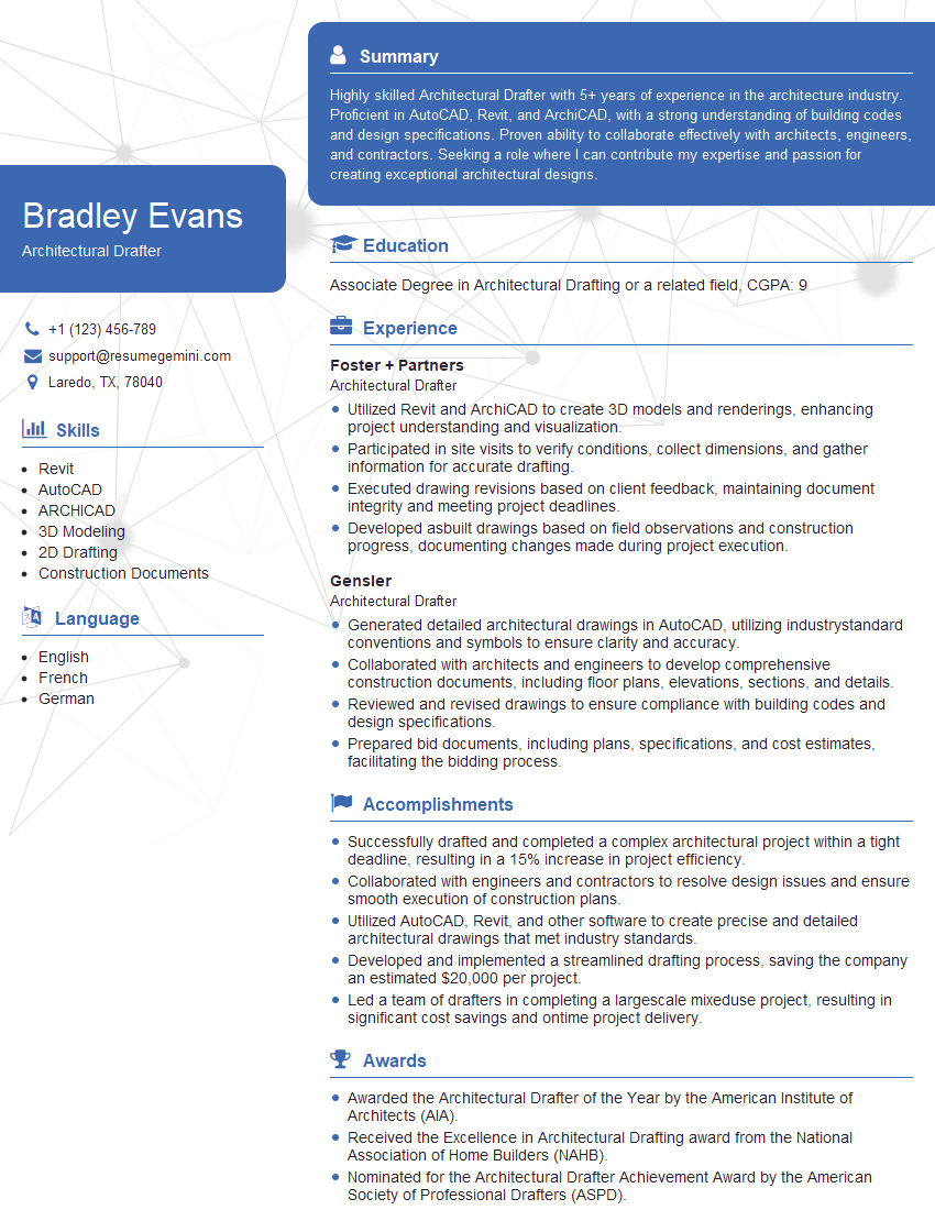
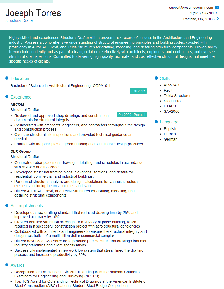
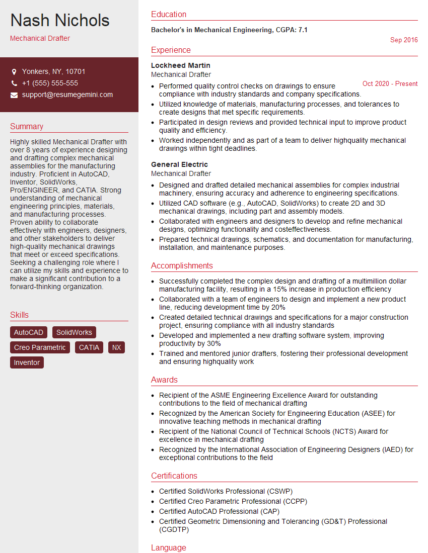
Mastering Engineering Drawing Creation is crucial for a successful career in engineering, opening doors to diverse and challenging roles. A strong understanding of these concepts will significantly improve your interview performance and showcase your capabilities. To maximize your job prospects, focus on building an ATS-friendly resume that highlights your skills and experience effectively. ResumeGemini is a trusted resource to help you create a professional and impactful resume. We provide examples of resumes tailored to Engineering Drawing Creation to guide you in showcasing your expertise. Invest time in crafting a compelling resume – it’s your first impression on potential employers.
Explore more articles
Users Rating of Our Blogs
Share Your Experience
We value your feedback! Please rate our content and share your thoughts (optional).
What Readers Say About Our Blog
Hello,
We found issues with your domain’s email setup that may be sending your messages to spam or blocking them completely. InboxShield Mini shows you how to fix it in minutes — no tech skills required.
Scan your domain now for details: https://inboxshield-mini.com/
— Adam @ InboxShield Mini
Reply STOP to unsubscribe
Hi, are you owner of interviewgemini.com? What if I told you I could help you find extra time in your schedule, reconnect with leads you didn’t even realize you missed, and bring in more “I want to work with you” conversations, without increasing your ad spend or hiring a full-time employee?
All with a flexible, budget-friendly service that could easily pay for itself. Sounds good?
Would it be nice to jump on a quick 10-minute call so I can show you exactly how we make this work?
Best,
Hapei
Marketing Director
Hey, I know you’re the owner of interviewgemini.com. I’ll be quick.
Fundraising for your business is tough and time-consuming. We make it easier by guaranteeing two private investor meetings each month, for six months. No demos, no pitch events – just direct introductions to active investors matched to your startup.
If youR17;re raising, this could help you build real momentum. Want me to send more info?
Hi, I represent an SEO company that specialises in getting you AI citations and higher rankings on Google. I’d like to offer you a 100% free SEO audit for your website. Would you be interested?
Hi, I represent an SEO company that specialises in getting you AI citations and higher rankings on Google. I’d like to offer you a 100% free SEO audit for your website. Would you be interested?
good
