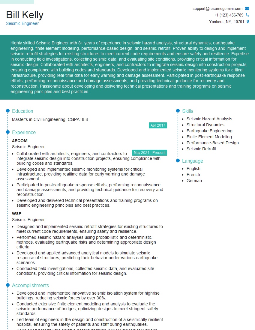
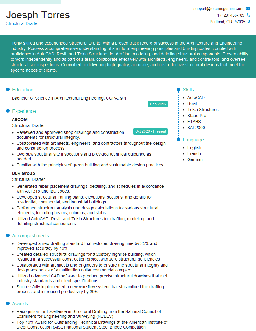
Preparation is the key to success in any interview. In this post, we’ll explore crucial Structural Analysis and Engineering interview questions and equip you with strategies to craft impactful answers. Whether you’re a beginner or a pro, these tips will elevate your preparation.
Questions Asked in Structural Analysis and Engineering Interview
Q 1. Explain the difference between static and dynamic analysis.
Static analysis assumes that loads applied to a structure are constant and unchanging over time. Think of a building supporting its own weight and the weight of furniture – the loads are relatively static. In contrast, dynamic analysis considers loads that vary with time, such as wind gusts, earthquakes, or the impact of a vehicle. This variation introduces inertia and acceleration effects, making the analysis significantly more complex.
Imagine a bridge: static analysis would determine if it can support its own weight and the weight of vehicles at rest. Dynamic analysis would additionally assess its response to a passing truck (a sudden load), or the vibrations induced by strong winds.
The key difference lies in the consideration of time-dependent effects. Static analysis is simpler and computationally less intensive, while dynamic analysis requires more sophisticated techniques and modelling to account for the time-varying nature of the loads and the structure’s response.
Q 2. Describe different types of structural loads and their effects.
Structural loads can be broadly categorized into:
- Dead Loads: These are permanent loads acting on a structure, such as the self-weight of structural elements (beams, columns, slabs), finishes, and fixtures. Think of the weight of the concrete in a building.
- Live Loads: These are temporary or movable loads, including occupancy loads (people, furniture), vehicular traffic, snow, and equipment. The weight of people in an office building would be a live load.
- Wind Loads: Caused by wind pressure and suction, these loads are highly variable and depend on wind speed, building shape, and height. They can cause significant stresses and even uplift on tall structures.
- Earthquake Loads: These inertial forces are generated during seismic events and can be highly destructive. The impact is a function of ground motion intensity and building characteristics.
- Environmental Loads: These include snow loads (weight of accumulated snow), rain loads (hydrostatic pressure on retaining walls), and temperature changes (leading to thermal stresses).
- Impact Loads: These are sudden, dynamic forces resulting from collisions or explosions, causing high stress concentrations.
The effects of these loads depend on their magnitude, duration, and point of application. They lead to stresses, strains, deflections, and potentially structural failure if they exceed the structure’s capacity.
Q 3. What are the key assumptions made in linear elastic analysis?
Linear elastic analysis rests on several key assumptions:
- Linearity: The relationship between stress and strain is linear, meaning that stress is directly proportional to strain (Hooke’s Law applies). This means that doubling the load doubles the deflection.
- Elasticity: The material returns to its original shape once the load is removed. No permanent deformation occurs.
- Small Deformations: Deflections are small compared to the overall dimensions of the structure. This allows for simplification in calculations, as we don’t need to account for geometric non-linearities.
- Homogeneity: The material properties are uniform throughout the structure. The material is the same everywhere.
- Isotropy: The material has the same properties in all directions. The material behaves identically regardless of the direction of the force applied.
These assumptions simplify the analysis considerably, but it’s crucial to remember that they might not hold in all real-world situations. For instance, a structure experiencing large deflections or made of non-linear materials (like concrete under high compression) would require non-linear analysis.
Q 4. How do you determine the buckling load of a column?
The buckling load of a column, the critical load at which it loses stability and buckles, can be determined using Euler’s formula for slender columns:
Pcr = (π²EI) / (KL)²
Where:
Pcris the critical buckling load.Eis the modulus of elasticity of the column material.Iis the area moment of inertia of the column cross-section (about the axis of bending).Lis the effective length of the column.Kis the effective length factor, accounting for end conditions (e.g., pinned-pinned, fixed-fixed, fixed-free).Kvaries between 0.5 and 2.
The effective length accounts for how the column’s ends are supported; a column fixed at both ends is stiffer than one pinned at both ends. Different end conditions significantly alter the buckling load. To determine the buckling load, you need the material properties (E), the geometry of the column (I, L), and appropriate boundary conditions to find K.
Q 5. Explain the concept of moment of inertia and its significance in structural analysis.
The moment of inertia (also called the second moment of area) is a geometrical property that describes a cross-section’s resistance to bending. It represents how the area of a cross-section is distributed relative to its neutral axis. A larger moment of inertia means greater resistance to bending. Imagine trying to bend a wooden plank versus a metal I-beam. The I-beam, with its much larger moment of inertia, is far more resistant to bending.
In structural analysis, the moment of inertia is crucial in calculating:
- Bending stresses and deflections: A larger moment of inertia results in lower bending stresses and smaller deflections for a given bending moment.
- Column buckling: As seen in Euler’s formula, the moment of inertia is directly related to the buckling load of a column.
- Torsional stiffness: The polar moment of inertia, a related concept, is crucial in assessing a member’s resistance to torsion.
In essence, the moment of inertia is a key indicator of a structural member’s strength and stiffness in resisting bending loads.
Q 6. What are the different methods for analyzing indeterminate structures?
Indeterminate structures have more reactions than equations of equilibrium, meaning static equilibrium alone isn’t enough to determine the internal forces and reactions. We need additional methods:
- Force Method (Flexibility Method): This method introduces redundant forces, solving for them using compatibility equations (ensuring displacements are consistent with the support conditions). It’s useful for small numbers of redundants.
- Displacement Method (Stiffness Method): This method solves for displacements at key points using the structure’s stiffness matrix, then relates these displacements to internal forces. This method is computationally efficient for large and complex structures and forms the basis of Finite Element Analysis.
- Slope-Deflection Method: A displacement method often used for continuous beams and frames, relating joint moments and rotations.
- Moment Distribution Method: An iterative method for analyzing indeterminate structures by distributing moments between members based on their stiffness. It provides an intuitive understanding of load distribution.
The choice of method depends on the complexity of the structure and the tools available. FEA software typically employs the displacement method due to its computational efficiency for large-scale problems.
Q 7. Describe your experience with Finite Element Analysis (FEA) software.
I have extensive experience using various FEA software packages, including ANSYS, ABAQUS, and Autodesk Robot Structural Analysis. My work has ranged from simple linear static analyses of beams and frames to complex non-linear dynamic simulations involving large-scale structures.
For example, in one project, I used ANSYS to model and analyze the seismic response of a multi-story building. This involved creating a detailed 3D finite element model, defining material properties, applying seismic loads according to relevant codes, and analyzing the resulting stresses, displacements, and mode shapes. I used the results to optimize the structural design for improved seismic resilience.
In another project, I used ABAQUS for non-linear analysis of a welded joint under fatigue loading. This required careful mesh generation around the weld, material modeling considering plasticity, and the application of cyclic loading to determine the fatigue life of the joint.
My FEA skills encompass model creation, mesh generation, material modeling, load application, solution processing, and result interpretation. I am adept at selecting appropriate analysis types and interpreting results to inform design decisions. I also have experience using various pre- and post-processing tools to enhance workflow efficiency. I am proficient in validating FEA results against analytical solutions or experimental data where applicable.
Q 8. How do you account for seismic loads in structural design?
Accounting for seismic loads in structural design is crucial for ensuring the safety and longevity of structures in earthquake-prone regions. We use a response spectrum analysis or time-history analysis to determine the forces imposed by the earthquake on the structure. This involves considering several factors:
- Seismic Zone: The geographical location determines the design ground motion parameters.
- Soil Type: The soil’s properties influence how seismic waves propagate, impacting the structural response.
- Building Occupancy: The intended use of the building dictates the allowable level of damage and the importance factor.
- Structural System: Different structural systems (e.g., moment frames, braced frames) have varying capacities to resist seismic forces.
The analysis typically uses response spectra to define the maximum acceleration, velocity, and displacement that the structure might experience. These values are then used to calculate equivalent static loads or dynamic loads for design. For example, in a response spectrum analysis, we’d input the building’s characteristics (mass, stiffness) and the ground motion spectrum into structural analysis software. The output provides the forces and moments acting on the structural elements, allowing engineers to design members capable of withstanding these loads.
In practice, this often involves designing for ductility – the structure’s ability to deform significantly without failure – using detailing techniques like special moment connections and ensuring adequate reinforcement in critical regions to dissipate energy during an earthquake.
Q 9. What are the different types of structural steel sections and their applications?
Structural steel sections come in a variety of shapes, each with its unique properties and applications. Common types include:
- Wide-Flange (W) Sections: These are the workhorses of steel construction, efficient in bending and shear, used extensively in beams and columns of buildings and bridges. Think of the I-beam shape – strong and versatile.
- American Standard (S) Sections: Similar to W-sections but with a smaller flange width to depth ratio, suitable for situations with less bending moment.
- Hollow Structural Sections (HSS): These are tubular sections, offering high strength-to-weight ratios and good torsional rigidity. They are excellent for applications requiring high stiffness and resistance to buckling, like tubular columns or bracing members.
- Channels (C): C-shaped sections are typically used as beams or as components in built-up sections, providing good bending strength in one direction.
- Angles (L): Used for bracing, connections, and as part of built-up sections, offering strength in two directions.
- Tees (WT): Similar to wide-flange sections but with only one flange, used often as beams.
The choice of section depends on factors such as load capacity, span length, cost, and architectural considerations. For instance, in a high-rise building, W-sections might be preferred for primary beams and columns due to their high load-bearing capacity, while HSS sections could be used for bracing to provide lateral stability.
Q 10. Explain the concept of shear center and its importance.
The shear center is the point through which a shear force must act to produce bending without torsion. Imagine trying to push a thin, flat piece of metal: if you push it off-center, it will twist. The shear center represents that center point. For a symmetrical section (like a wide-flange beam), the shear center coincides with the centroid (geometric center). However, for sections with asymmetry, like channels or angles, the shear center is offset from the centroid.
Its importance lies in avoiding undesirable torsional effects. If a shear force acts through the shear center, only bending will occur. But if it’s applied away from the shear center, it’ll induce both bending and twisting, potentially leading to increased stresses and structural failure. For example, a channel section used as a beam will experience torsion if the load is not applied directly through the shear center, even if the load is small. This torsion must be accounted for during design.
Accurately locating the shear center is crucial for accurate load analysis, and software tools and engineering handbooks are frequently used for this purpose. For more complex cross-sections, it might be calculated using advanced methods or through finite element analysis.
Q 11. How do you design for wind loads?
Designing for wind loads involves determining the forces exerted by wind on a structure and ensuring the structure can withstand them. This requires understanding wind speed, pressure distribution, and the shape and size of the structure. The process typically involves:
- Determining Wind Speed: We consult meteorological data and building codes to establish the design wind speed for the specific location.
- Wind Pressure Calculation: Using wind speed and the building’s shape, we calculate the wind pressure using aerodynamic principles and equations outlined in building codes. We consider effects such as wind direction, height above ground, and building shape, including effects from surrounding structures.
- Force Determination: We convert the calculated wind pressures into forces acting on different parts of the building – walls, roofs, etc. The size and configuration of the structure significantly influence how wind pressures are calculated and ultimately distributed.
- Structural Design: The forces calculated determine the size and type of structural elements required to resist the wind loads. This often involves the selection of appropriate bracing systems, ensuring adequate stiffness, and designing elements (beams, columns, connections) to resist the lateral forces.
Real-world application involves using specialized software to model wind loads on complex building shapes, ensuring that buildings are designed to withstand strong winds without excessive deflection or damage. For instance, tall buildings need detailed analysis to account for wind vortex shedding, while low-rise buildings might require simpler calculations focusing on static wind loads.
Q 12. What are the different types of foundation systems and their suitability?
Foundation systems are crucial for transferring structural loads safely to the underlying soil. Several types exist, each suitable for specific conditions:
- Shallow Foundations: These include footings (individual or combined), strip footings, and rafts (mats). They are suitable for structures with moderate loads and stable soils with sufficient bearing capacity. For example, a small house might use individual spread footings, while a long wall could employ a strip footing.
- Deep Foundations: These are used when shallow foundations are unsuitable due to weak soil or deep loads. Types include piles (driven, bored, or cast-in-place), piers, and caissons. For example, a high-rise building or a bridge pier might necessitate deep foundations.
- Pile Foundations: These are used when the soil has low bearing capacity. Piles transfer the load to stronger soil strata deeper down. They can be made of steel, concrete, or timber. Their selection depends on various factors such as soil conditions and load requirements.
- Mat Foundations: These are used for large, heavy structures where the loads are distributed over a large area. They’re cost-effective when soil conditions are poor and many columns are present. Think of a large warehouse or industrial plant.
Selecting the appropriate foundation requires geotechnical investigation to determine soil properties, load capacity, and groundwater conditions. This investigation guides the design of a foundation system that is both safe and economical.
Q 13. Describe your experience with reinforced concrete design.
I have extensive experience in reinforced concrete design, encompassing all stages from conceptual design to detailed drawings and specifications. My experience includes working on a wide range of projects, including residential, commercial, and industrial structures. I’m proficient in using analysis software such as ETABS and SAP2000 to model concrete structures and calculate reinforcement requirements.
My work involves designing reinforced concrete beams, columns, slabs, footings, and retaining walls, paying close attention to detailing to ensure structural integrity and durability. I’m familiar with various design codes (e.g., ACI 318) and understand the importance of considering factors such as material properties, load combinations, crack control, and durability. I regularly utilize design aids and calculation software to streamline the design process, whilst also employing manual calculations to confirm software outputs and verify accuracy.
A recent example involved designing a multi-story parking garage, where I had to carefully consider the structural design to account for heavy loads and potential shrinkage and creep. This required detailed analysis and design of the column and beam sections and the use of advanced techniques to account for the complex load paths.
Q 14. Explain the concept of deflection and its limitations.
Deflection refers to the displacement or deformation of a structural element under load. It’s essential to limit deflection to ensure the structure remains functional and aesthetically pleasing. Excessive deflection can lead to cracking, damage, and even structural failure.
Deflection limits are set by building codes and depend on factors such as the type of structure, material properties, and intended use. For example, excessive deflection in a floor slab can cause cracking of finishes and discomfort for occupants, while deflection in a beam might affect its ability to support secondary elements. For instance, excessive deflection in a beam supporting a brick wall could crack the masonry.
Limiting deflection often involves adjusting the structural element’s size or using stiffer materials. Excessive deflection can also indicate potential design issues, such as inadequate member sizes or improper support conditions. It’s important to consider both serviceability (limiting deflection) and strength (preventing failure) when designing a structure. The acceptable deflection limits are usually a fraction of the span length, with more stringent limits for elements supporting sensitive finishes or equipment.
Q 15. How do you account for creep and shrinkage in concrete design?
Creep and shrinkage are time-dependent deformations in concrete. Creep refers to the continued deformation under sustained load, while shrinkage is the reduction in volume due to moisture loss. We account for these effects in design to prevent excessive deflections and cracking.
How we account for them:
- Using design codes: Codes like ACI 318 provide methods to estimate creep and shrinkage based on factors like concrete mix proportions, environmental conditions (temperature and humidity), and member size. These codes often provide reduction factors applied to calculated stresses or deflections.
- Finite Element Analysis (FEA): For complex structures or situations where code provisions are insufficient, FEA is employed. Time-dependent material models are incorporated into the analysis to simulate the creep and shrinkage effects accurately. This allows for prediction of long-term deflections and stress redistribution.
- Adjusting design parameters: Based on the predicted creep and shrinkage, we may need to increase member sizes, adjust reinforcement details, or introduce prestressing to counteract the anticipated deformations. For example, in a long-span beam, we might increase the depth to minimize deflection due to creep.
Example: In a high-rise building, neglecting creep and shrinkage could lead to significant long-term deflections exceeding allowable limits, causing problems with building functionality and aesthetics. Accurate prediction and compensation for these effects are critical.
Career Expert Tips:
- Ace those interviews! Prepare effectively by reviewing the Top 50 Most Common Interview Questions on ResumeGemini.
- Navigate your job search with confidence! Explore a wide range of Career Tips on ResumeGemini. Learn about common challenges and recommendations to overcome them.
- Craft the perfect resume! Master the Art of Resume Writing with ResumeGemini’s guide. Showcase your unique qualifications and achievements effectively.
- Don’t miss out on holiday savings! Build your dream resume with ResumeGemini’s ATS optimized templates.
Q 16. What are the different failure modes of structural members?
Structural members can fail in various ways, broadly categorized as:
- Flexural Failure: This occurs when a member bends excessively under load, leading to cracking and eventual collapse. Think of a simply supported beam failing due to excessive bending moment.
- Shear Failure: This happens when the internal shear stresses exceed the material’s shear strength, often resulting in sudden and catastrophic failure. Examples include web crippling in beams and shear failure in columns.
- Torsional Failure: This occurs when a member is subjected to twisting moments beyond its torsional capacity. Shaft or bridge members are particularly susceptible to this type of failure.
- Buckling Failure: Slender members under compressive loads can buckle, losing stability before reaching their ultimate compressive strength. Columns and slender struts are prone to buckling.
- Compression Failure: This involves crushing or yielding of the material under compressive stresses. Short, stout columns are more susceptible to this type of failure.
- Bond Failure: In reinforced concrete, this failure occurs when the bond between the concrete and the reinforcement breaks down, leading to slippage of the reinforcement and loss of strength.
Understanding these failure modes is crucial for proper design to ensure sufficient safety margins and prevent premature failures.
Q 17. What are your experiences with different building codes (e.g., IBC, ASCE)?
I have extensive experience working with various building codes, including the International Building Code (IBC) and ASCE standards. My work frequently involves navigating the specific requirements of these codes depending on the project location and structural system. I’m familiar with the load combinations, material specifications, and design procedures detailed in these documents.
For example, when designing a structure in a seismic zone, I meticulously apply the seismic design provisions of the IBC or relevant ASCE standards to ensure the structure can withstand earthquake loads. Similarly, I utilize relevant provisions for wind loads and other environmental factors. My experience covers both the application of these codes for design and the associated review and analysis of existing structures.
Q 18. Explain your approach to solving a complex structural problem.
My approach to solving complex structural problems is systematic and iterative. It involves:
- Problem Definition: Thoroughly understanding the project goals, constraints (geotechnical, budgetary, aesthetic), and the specific structural challenges. This often involves site visits and discussions with architects, clients and other stakeholders.
- Conceptual Design: Exploring different structural systems and preliminary design concepts to identify the most efficient and feasible solution. This includes preliminary calculations and sketches to compare various options.
- Detailed Analysis: Performing detailed structural analysis using appropriate methods (FEA, hand calculations, etc.) to assess the structural behavior under various load conditions. This involves selecting appropriate software and validating results against code requirements.
- Design Optimization: Iteratively refining the design to meet all requirements while optimizing for cost, material usage, and constructability. This often involves exploring different configurations and materials.
- Documentation and Review: Preparing comprehensive design drawings, calculations, and reports. This ensures clarity and facilitates effective communication and review by peers and clients.
Throughout the process, I emphasize collaboration, communication, and continuous learning. Complex problems often require a multidisciplinary approach, and I am comfortable working with specialists in geotechnical engineering, MEP engineering, and construction management.
Q 19. How do you handle uncertainties and variations in material properties?
Uncertainties in material properties are inherent in structural engineering. We address these uncertainties through various techniques:
- Material Testing: Before construction, we often specify material testing to verify the actual properties against design assumptions. This could include concrete cylinder testing for compressive strength and steel coupon testing for yield strength.
- Partial Safety Factors: Building codes incorporate partial safety factors to account for the uncertainties in material properties and loads. These factors increase the design loads and reduce the material strengths, providing a safety margin.
- Probabilistic Methods: For critical structures, we might employ probabilistic methods such as Monte Carlo simulations. This involves creating a statistical model of the uncertainties and running multiple simulations to estimate the probability of failure.
- Sensitivity Analysis: We perform sensitivity analysis to determine which parameters have the largest impact on the structural response. This helps prioritize areas requiring more careful attention and potentially more detailed investigation.
For example, when designing a bridge, I might use higher strength factors to compensate for potential variations in concrete strength. The goal is to provide reliable and safe structures by accounting for the inherent variability of materials.
Q 20. Describe your experience with structural detailing and drawing review.
I have extensive experience in structural detailing and drawing review. This is critical for ensuring the structural design is accurately translated into constructible plans. My responsibilities include:
- Creating detailed drawings: Producing clear and accurate drawings showing reinforcement details, connection designs, dimensions, and material specifications. This includes utilizing CAD software proficiently.
- Checking drawings for errors: Thoroughly reviewing drawings to identify potential clashes, inconsistencies, and omissions. This involves a detailed check against design calculations and code requirements.
- Ensuring constructability: Considering the practical aspects of construction during detailing. This includes ensuring that the design is feasible and cost-effective to build. I’ll consult with construction professionals if needed to make sure the details are feasible.
- Maintaining standards: Adhering to company standards and best practices for drafting and detailing to produce high-quality, professional documents.
Example: I once identified a clash between the HVAC system and a structural beam during drawing review, preventing potential construction delays and extra costs.
Q 21. Explain the concept of stress concentration and its mitigation.
Stress concentration occurs when stress increases locally around geometric discontinuities like holes, notches, or sharp corners in a structural member. This localized stress can be significantly higher than the nominal stress, increasing the likelihood of failure. Imagine pulling on a piece of paper with a small hole in it—the paper is much more likely to tear at the hole.
Mitigation strategies include:
- Fillet radii: Adding smooth transitions (fillets) at corners and intersections reduces stress concentration by distributing stress over a larger area.
- Hole reinforcement: For holes in members, reinforcing the hole region with larger material thickness or additional reinforcement can help.
- Stress relieving features: Incorporating features such as chamfers or using a more gradual transition can lessen the stress concentration.
- Finite Element Analysis (FEA): FEA can accurately model stress concentration and help identify areas needing improved design. We can then optimize the geometry or add reinforcement to manage the high stress region.
- Material Selection: Selecting materials with higher ductility and toughness can improve the structure’s resistance to failure even with stress concentration.
Example: In a pressure vessel, stress concentration around welds is carefully considered, and appropriate design techniques are used to minimize the risk of failure at these locations.
Q 22. What are your experiences using various analysis software (e.g., SAP2000, ETABS, ABAQUS)?
My experience with structural analysis software is extensive, encompassing a range of programs tailored to different project needs. I’m proficient in SAP2000, a powerful tool ideal for analyzing complex building structures, from high-rise buildings to bridges. I utilize its advanced features for linear and nonlinear analysis, including seismic and wind load simulations. ETABS shares similar capabilities, excelling in the efficient modeling of multi-story structures. I’ve used it extensively for projects requiring detailed analysis of building frames and shear walls. Finally, ABAQUS provides a much more versatile finite element analysis (FEA) platform, allowing for highly detailed simulations of complex material behavior and non-linear effects. I’ve used ABAQUS for specialized projects requiring detailed stress analysis of components, including fatigue analysis and fracture mechanics studies. For example, in one project, I leveraged ABAQUS’s capabilities to model the complex stress distribution in a welded joint under cyclic loading.
- SAP2000: Used for the analysis of a 20-story steel-framed building, incorporating dynamic analysis for seismic loading.
- ETABS: Employed for the design of a reinforced concrete parking structure, focusing on shear wall design and detailing.
- ABAQUS: Utilized in a research project to model the failure mechanism of a composite material under extreme loading conditions.
Q 23. Describe a time you had to troubleshoot a structural analysis problem.
During the analysis of a large-span timber roof structure, I encountered unexpected results. The initial analysis predicted significantly higher bending moments than anticipated. Troubleshooting involved a systematic approach:
- Review of the Model: I meticulously checked the model geometry, ensuring the correct dimensions and boundary conditions were applied. This revealed a minor error in the support conditions.
- Material Properties: I verified the accuracy of the timber material properties used in the analysis. Consulting relevant design codes and material data sheets resolved a minor discrepancy in the modulus of elasticity.
- Mesh Refinement: To ensure accuracy in high stress regions, I refined the finite element mesh around the critical areas. This highlighted a localized stress concentration.
- Load Case Review: I reevaluated the applied load cases, paying particular attention to the distribution and magnitude of the snow load. This process revealed an oversight in the snow load calculation.
By systematically investigating each aspect of the model and analysis, I identified and corrected the errors, leading to a more accurate and realistic prediction of the structural behavior. The corrected analysis showed significantly reduced bending moments, alleviating design concerns.
Q 24. How do you ensure the accuracy and reliability of your structural analysis?
Ensuring the accuracy and reliability of structural analysis is paramount. My approach involves a multi-faceted strategy:
- Independent Verification: I always perform independent checks of the analysis results. This often involves using different software packages or employing hand calculations for simpler aspects of the structure. This acts as a second layer of validation.
- Peer Review: Collaborating with colleagues for peer review helps identify potential oversights or errors. A fresh perspective can catch subtleties that I may have missed.
- Code Compliance: Adherence to relevant building codes and standards is crucial. I ensure the analysis methods and design assumptions comply with the prevailing regulations.
- Sensitivity Studies: I perform sensitivity studies by varying input parameters (e.g., material properties, loads) to assess their impact on the analysis results. This helps gauge the uncertainty associated with the analysis.
- Model Validation: Where possible, I compare the analytical results with experimental data from field measurements or laboratory testing. This provides a critical validation of the analysis model.
This rigorous approach significantly reduces the risk of errors and promotes confidence in the accuracy of the structural analysis.
Q 25. Explain the concept of fatigue and its implications in structural design.
Fatigue refers to the progressive and localized structural damage that occurs when a material is subjected to cyclic loading. Imagine repeatedly bending a paperclip back and forth – eventually, it will break, even though the force applied in each cycle might be far less than what’s required to break it in a single application. This is fatigue failure.
In structural design, fatigue is a major consideration, especially for structures subjected to repeated loading cycles, like bridges, aircraft, and offshore platforms. Fatigue can lead to unexpected and catastrophic failures if not properly accounted for. The design process involves analyzing the expected number of load cycles and the stress range experienced during each cycle. Design codes provide fatigue design guidelines and allowable stress limits to ensure the structure has a sufficient fatigue life.
For example, in bridge design, fatigue analysis is critical for the welded joints in the structure, as these are prone to fatigue crack initiation and propagation due to fluctuating live loads (vehicles).
Q 26. How familiar are you with different types of connections (e.g., bolted, welded)?
My familiarity with different types of structural connections is comprehensive. I have experience designing and analyzing various connection types, including:
- Bolted Connections: I’m proficient in designing bolted connections, considering factors like bolt diameter, spacing, edge distance, and shear and tension capacity. I also understand the importance of proper detailing to prevent bolt loosening and failure.
- Welded Connections: I have expertise in designing welded connections, selecting appropriate weld types (e.g., fillet welds, butt welds), sizes, and detailing to ensure sufficient strength and durability. I also account for potential weld defects and their impact on strength.
- Riveted Connections: While less common in modern construction, I possess knowledge of riveted connections, understanding the design criteria and limitations of this connection type.
The choice of connection type depends on factors like the structural material, load conditions, fabrication constraints, and cost-effectiveness. For example, in steel structures, bolted connections are often preferred due to their ease of assembly and adaptability. Welded connections are common where high strength and stiffness are required, particularly in heavy industrial applications. Accurate modeling of connection behavior is crucial for reliable structural analysis, and I employ detailed FEA if necessary.
Q 27. What are your experiences with design for sustainability and environmental considerations?
Sustainability and environmental considerations are integral parts of my design philosophy. My experience includes:
- Material Selection: I prioritize the use of sustainable and environmentally friendly materials like recycled steel, timber from responsibly managed forests, and low-embodied-carbon concrete. Life-cycle assessment (LCA) of materials helps in making informed decisions.
- Optimized Designs: I strive to create optimized designs that minimize material usage and reduce construction waste. This not only reduces the environmental impact but also lowers construction costs.
- Embodied Carbon Reduction: I actively seek to reduce the embodied carbon in structures by selecting low-carbon materials, optimizing structural design, and exploring carbon offsetting strategies.
- Energy Efficiency: Incorporating energy-efficient design principles into structural design, including considering natural ventilation and daylighting, is a core aspect of my work.
For example, in a recent project, we used cross-laminated timber (CLT) for the structural frame of a building. CLT boasts superior strength-to-weight ratio and significantly lower embodied carbon compared to traditional concrete or steel structures.
Q 28. Describe your experience working in a collaborative team setting on a structural project.
I thrive in collaborative team environments. My experience working on large-scale structural projects has reinforced the importance of effective communication and teamwork. I’ve worked on multi-disciplinary teams involving architects, engineers (structural, mechanical, electrical), contractors, and clients. My role often involves:
- Clear Communication: Effectively communicating complex technical information to both technical and non-technical audiences is vital. I actively participate in meetings, presentations, and design reviews.
- Coordination: Coordinating the structural design with the architectural design and other engineering disciplines requires close collaboration and careful planning. I’ve used BIM software to facilitate this process.
- Problem Solving: Collaboration is key to solving complex design problems. Sharing ideas and perspectives fosters creative solutions. In one project, a collaborative effort identified a critical design flaw in the foundation, which was rectified through teamwork and open communication.
Effective teamwork leads to successful projects, optimized designs, and efficient use of resources. I view my role as a collaborative contributor, fostering a positive and productive team environment.
Key Topics to Learn for Your Structural Analysis and Engineering Interview
- Statics and Equilibrium: Understanding forces, moments, and reactions in statically determinate and indeterminate structures. Practical application: Analyzing the stability of a bridge design.
- Stress and Strain: Mastering stress-strain relationships, material properties (e.g., Young’s modulus, Poisson’s ratio), and failure theories. Practical application: Determining the appropriate material selection for a high-rise building.
- Structural Analysis Methods: Proficiency in methods such as method of joints, method of sections, influence lines, and matrix methods. Practical application: Analyzing the internal forces in a truss structure.
- Beam Theory: Understanding bending moments, shear forces, deflection, and beam design considerations. Practical application: Calculating the deflection of a beam under various loading conditions.
- Column Analysis: Understanding buckling behavior, critical loads, and column design. Practical application: Designing a safe and stable column for a multi-story building.
- Finite Element Analysis (FEA): Familiarity with the fundamentals of FEA and its application in structural analysis. Practical application: Simulating the structural behavior of complex geometries under various load cases.
- Structural Dynamics: Understanding the behavior of structures under dynamic loads (e.g., earthquakes, wind). Practical application: Designing earthquake-resistant structures.
- Material Behavior: Understanding the behavior of various materials (steel, concrete, timber) under stress and strain. Practical application: Selecting appropriate materials for specific structural applications.
- Code Compliance and Design Standards: Familiarity with relevant building codes and design standards. Practical application: Ensuring your designs meet safety and regulatory requirements.
- Problem-Solving & Communication: Ability to clearly communicate your analytical approach and solutions. Practical application: Effectively presenting your analysis and design recommendations to a team.
Next Steps
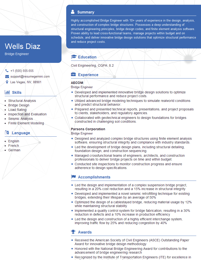
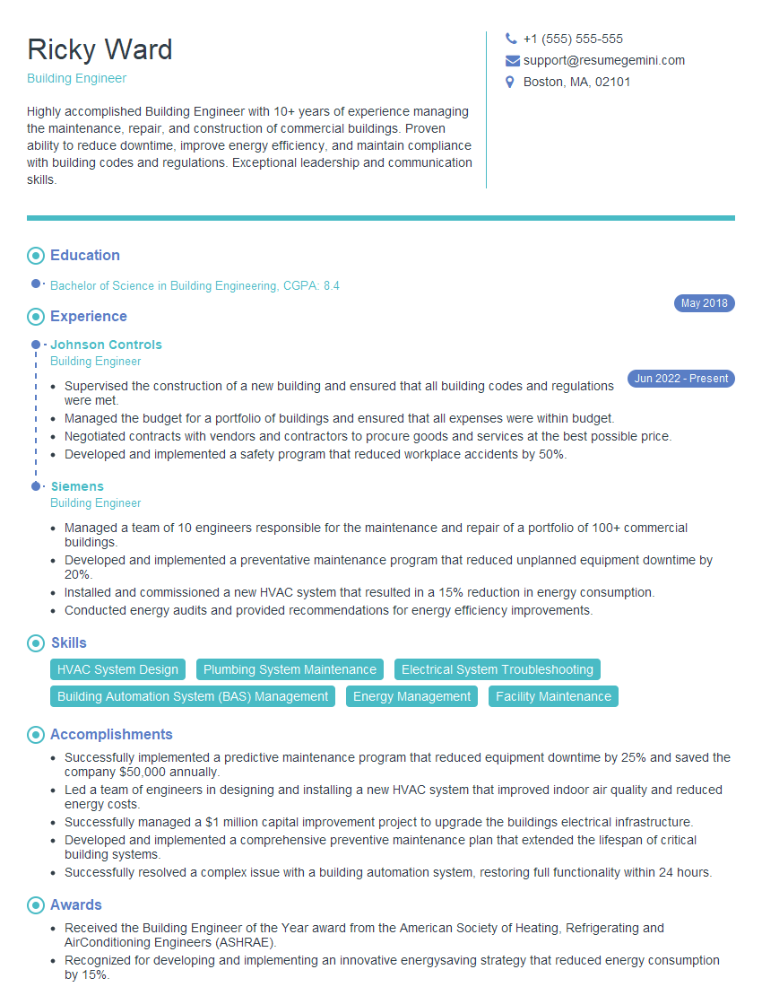
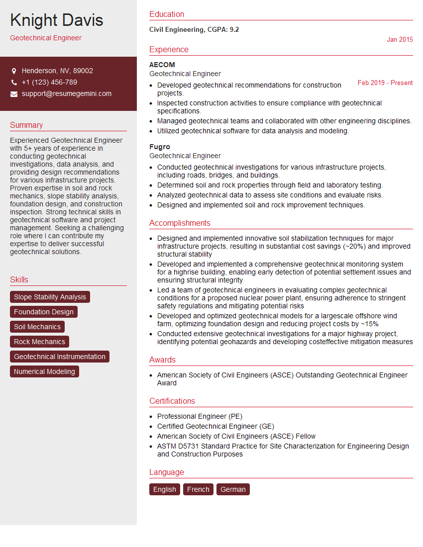
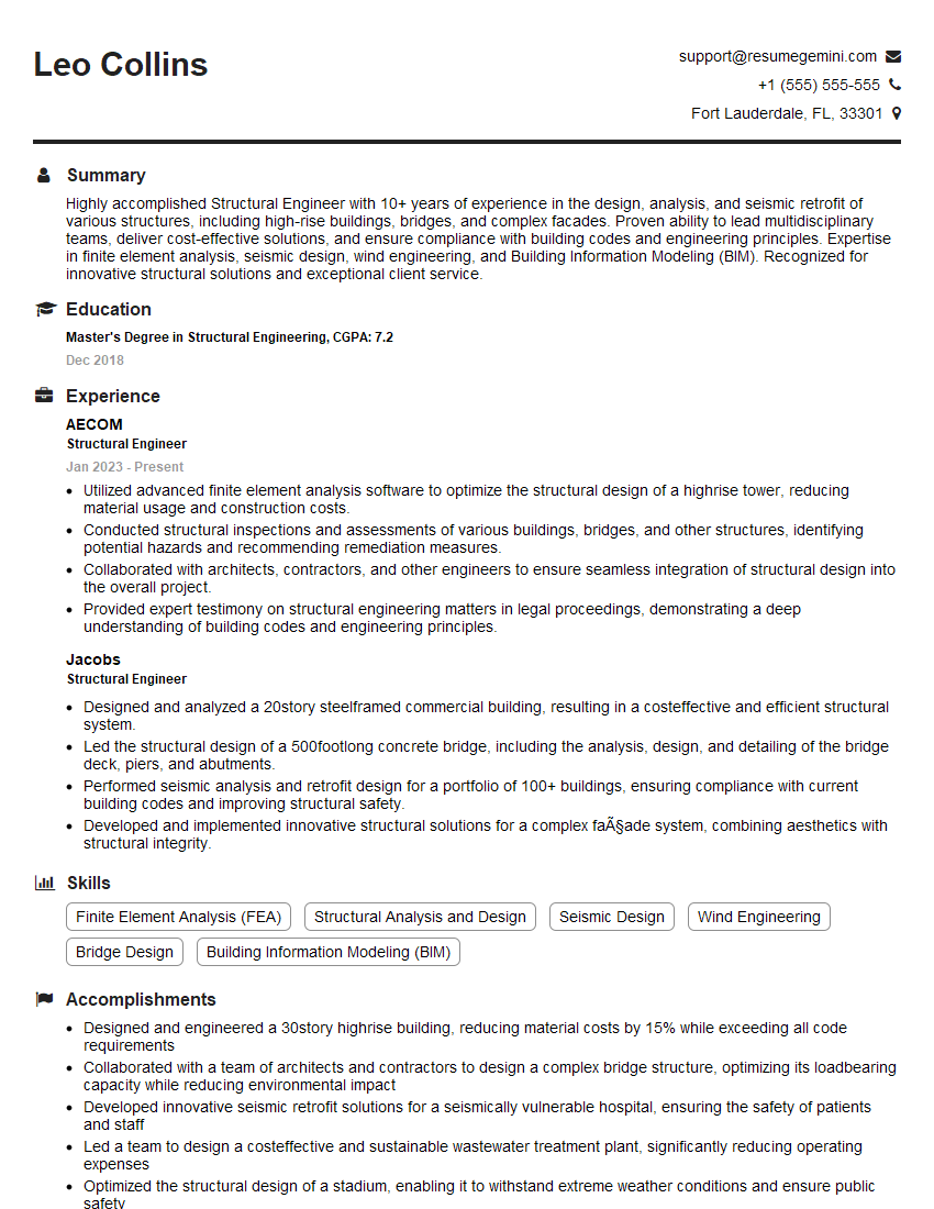
Mastering Structural Analysis and Engineering is crucial for a successful and rewarding career in this challenging and innovative field. Your expertise will be in high demand in the construction, infrastructure, and manufacturing sectors. To maximize your job prospects, create an ATS-friendly resume that highlights your skills and experience effectively. ResumeGemini is a trusted resource for building professional resumes, and we offer examples tailored specifically to Structural Analysis and Engineering to help you showcase your qualifications. Use this opportunity to present yourself as the ideal candidate!
Explore more articles
Users Rating of Our Blogs
Share Your Experience
We value your feedback! Please rate our content and share your thoughts (optional).
What Readers Say About Our Blog
Hello,
We found issues with your domain’s email setup that may be sending your messages to spam or blocking them completely. InboxShield Mini shows you how to fix it in minutes — no tech skills required.
Scan your domain now for details: https://inboxshield-mini.com/
— Adam @ InboxShield Mini
Reply STOP to unsubscribe
Hi, are you owner of interviewgemini.com? What if I told you I could help you find extra time in your schedule, reconnect with leads you didn’t even realize you missed, and bring in more “I want to work with you” conversations, without increasing your ad spend or hiring a full-time employee?
All with a flexible, budget-friendly service that could easily pay for itself. Sounds good?
Would it be nice to jump on a quick 10-minute call so I can show you exactly how we make this work?
Best,
Hapei
Marketing Director
Hey, I know you’re the owner of interviewgemini.com. I’ll be quick.
Fundraising for your business is tough and time-consuming. We make it easier by guaranteeing two private investor meetings each month, for six months. No demos, no pitch events – just direct introductions to active investors matched to your startup.
If youR17;re raising, this could help you build real momentum. Want me to send more info?
Hi, I represent an SEO company that specialises in getting you AI citations and higher rankings on Google. I’d like to offer you a 100% free SEO audit for your website. Would you be interested?
Hi, I represent an SEO company that specialises in getting you AI citations and higher rankings on Google. I’d like to offer you a 100% free SEO audit for your website. Would you be interested?
good
