Are you ready to stand out in your next interview? Understanding and preparing for AutoCAD Drafting interview questions is a game-changer. In this blog, we’ve compiled key questions and expert advice to help you showcase your skills with confidence and precision. Let’s get started on your journey to acing the interview.
Questions Asked in AutoCAD Drafting Interview
Q 1. Explain the difference between absolute and relative coordinates in AutoCAD.
In AutoCAD, coordinates define the location of points for drawing. Absolute coordinates specify a point’s location directly from the origin (0,0) of the drawing. Relative coordinates, on the other hand, define a point’s location relative to the last point you’ve drawn or selected. Think of it like giving directions: absolute coordinates are like providing a full address, while relative coordinates are like saying “go two blocks east, then one block north.”
Absolute Coordinates: You specify both the X and Y values directly. For example, 10,5 would place a point 10 units along the X-axis and 5 units along the Y-axis from the origin. -5,12 would place a point 5 units to the left of the origin and 12 units up.
Relative Coordinates: You use the @ symbol followed by the X and Y offsets from the previous point. For instance, if your last point was at 10,5, entering @2,3 would place the next point at 12,8 (10+2, 5+3). @-4,-2 would place the point at 6,3 (10-4, 5-2).
In practice, understanding both types is crucial for efficient drafting. Absolute coordinates are great for precisely placing objects from a known origin, while relative coordinates speed up drawing repetitive patterns or sketching freely.
Q 2. How do you create and manage layers in AutoCAD?
Layers are fundamental to organizing and managing the complexity of an AutoCAD drawing. Think of them as stacked sheets of transparent paper, each holding different elements of your design. This allows for selective visibility, control over object properties (like color, linetype, and lineweight), and efficient plotting.
Creating Layers: You can create new layers using the Layer Properties Manager (LAYPRO) or the command line (LAYER). In the Layer Properties Manager, you simply click ‘New’ and provide a descriptive name for your layer. On the command line, type LAYER, then NEW, and then enter the layer name. It’s good practice to use a naming convention (e.g., ‘Walls’, ‘Doors’, ‘Plumbing’) for better organization.
Managing Layers: The Layer Properties Manager lets you control various properties for each layer, including its color, linetype, lineweight, plot style, and whether it’s frozen (hidden) or locked (uneditable). You can also easily change the order of layers, affecting which ones appear on top. This is incredibly useful during a design review—you might temporarily freeze layers to focus only on specific aspects. Freezing unused layers significantly improves drawing performance, especially with large, complex projects.
Q 3. Describe your experience with different AutoCAD drawing tools (e.g., line, arc, circle, polyline).
My experience with AutoCAD’s drawing tools is extensive, encompassing the basic tools (line, arc, circle, polyline) and their advanced applications. I’ve utilized them across various projects ranging from simple 2D drafting to complex 3D modeling.
- Line: The foundational tool for creating straight lines, I use it constantly for defining boundaries, sketching outlines, and creating basic shapes. Precise control over length and angle is crucial.
- Arc: Essential for drawing curved elements, I’m adept at specifying arcs using various methods: radius, center point, start and end points, etc. This is critical for creating realistic representations of curved objects.
- Circle: Similar to the arc, circles are essential for various purposes – from simple design elements to defining the sweep of a pipe bend or hole location. Understanding diameter, radius, and center point input is key.
- Polyline: This versatile tool allows for creation of complex shapes comprised of multiple line segments and arcs. The ability to edit individual segments is particularly useful, making it ideal for complex building outlines or road design.
Beyond these basic tools, I’m proficient in using the spline command to create freeform curves, the rectangle command for efficient creation of rectangular shapes, and the ellipse command for creating ellipses and circles.
Q 4. How do you use the ‘snap’ and ‘grid’ settings for precision in AutoCAD?
The ‘snap’ and ‘grid’ settings are crucial for ensuring accuracy and precision in AutoCAD drawings. They act as guides, preventing accidental misplacements and aiding in creating drawings to exact specifications.
Grid: The grid is a visual background of evenly spaced dots or lines. It’s primarily a visual aid; it doesn’t constrain your drawing, but it helps maintain alignment and visualize distances. You can adjust the grid spacing to suit your drawing scale (e.g., a larger grid for a site plan, a smaller one for detailed mechanical components). You can toggle the grid on and off using the GRID command or the shortcut F7.
Snap: The snap setting constrains your cursor to specific points on the grid or objects. This allows for precise placement of objects, preventing minor deviations that accumulate and lead to inaccurate drawings. Different snap modes exist (endpoint, midpoint, intersection, etc.), giving you control over what points the cursor snaps to. Using object snaps ensures consistent accuracy for any project’s requirements.
Imagine building with LEGOs: the grid is like the baseplate, providing a visual framework, while snap is like having magnetic connections that guide the blocks to specific points. This ensures accurate assembly of the drawing.
Q 5. Explain your proficiency with AutoCAD’s dimensioning tools.
AutoCAD’s dimensioning tools are essential for creating professional-quality drawings that clearly communicate design intent. I’m proficient in creating various types of dimensions, including linear, angular, radial, and diameter dimensions. I understand the importance of dimension style management, ensuring consistency throughout a project.
My experience includes using different dimension styles for various types of drawings. For example, architectural drawings may require different dimension styles compared to mechanical or electrical drawings. I regularly use dimension constraints to help ensure that changes made to one part of a drawing automatically adjust other related dimensions and prevent conflicts, a critical aspect of complex drawings. Furthermore, I am familiar with using annotation scales to ensure that dimensions are displayed correctly at different plot scales. This prevents common mistakes seen when adjusting scaling across projects.
Beyond the basic functionality, I also utilize advanced techniques like creating associative dimensions (which dynamically update with object changes), managing dimension text styles, and controlling the overall appearance of dimensions for optimal readability and clarity.
Q 6. How do you create and edit blocks in AutoCAD?
Blocks are reusable collections of objects that can be inserted multiple times in a drawing, saving time and improving consistency. They’re like stamps or stencils, allowing you to quickly replicate frequently used components without redrawing them each time.
Creating Blocks: You create a block by selecting the objects you want to include, then using the BLOCK command. You give the block a name and specify an insertion point (typically the base point of the block). You can even create dynamic blocks, incorporating parameters that allow you to modify the block’s geometry interactively upon insertion (e.g., resizing, stretching).
Editing Blocks: Once a block is created, you can edit it by either ‘exploding’ it into its individual components or editing the block definition directly. Editing the block definition ensures that any changes are reflected in all instances of that block within the drawing, maintaining consistency. This is crucial for managing changes in standardized components across large projects.
For example, I’ve used blocks extensively to create standardized symbols for electrical components, HVAC equipment, or plumbing fixtures. In architectural drafting, blocks can represent doors, windows, and other repeating elements, thereby speeding up the overall drafting process. Proper block management simplifies drawing maintenance and updates.
Q 7. Describe your experience with using external references (xrefs) in AutoCAD.
External references (xrefs) are incredibly useful for managing large and complex projects, especially those involving multiple designers or consultants. An xref is a way to link another drawing file into your current drawing as a reference, updating automatically when the source drawing file is modified. It’s akin to linking a document instead of copying its contents.
My experience includes using xrefs to incorporate drawings from other disciplines (structural, MEP) into architectural drawings. I’m proficient in managing xref paths, attaching xrefs as either ‘overlay’ or ‘reference,’ and understanding the differences in how these affect edits and updates. ‘Overlay’ xrefs allow for direct editing of the referenced content within your drawing, whereas ‘reference’ xrefs only allow you to view and use the data without altering it directly. The choice depends on workflow and collaboration needs.
Imagine designing a building: the structural engineer might provide a structural drawing as an xref. When they update their model, your architectural drawing automatically reflects those changes. This ensures everyone works with the most up-to-date information and eliminates inconsistencies caused by manually updating drawings.
Q 8. How do you manage and organize large AutoCAD drawings?
Managing large AutoCAD drawings effectively is crucial for efficiency and preventing file corruption. My approach involves a multi-pronged strategy focusing on organization, external referencing, and proper layer management.
External Referencing (Xrefs): I break down complex drawings into manageable sections, saving each as a separate drawing file. These are then linked as external references (Xrefs) within a main drawing. This allows for easier modification and updating of individual parts without affecting the whole. Think of it like assembling a model kit – each piece is separate, but they come together to form the complete model. For example, in a building design, separate drawings might exist for architectural, structural, and MEP systems, all referenced within a master drawing.
Layer Management: I meticulously organize layers using a consistent naming convention (e.g., 01-Walls, 02-Doors, 03-Plumbing). This makes it easy to select, isolate, and modify specific elements. I also use layer states to control the visibility of layers, further simplifying navigation within the drawing. Imagine it like folders on your computer – each layer is a folder, containing specific information, allowing easy access and management.
Purge and Audit: Regularly purging unused blocks, layers, and styles reduces file size and improves performance. Auditing the drawing identifies and fixes potential errors, ensuring data integrity. This is akin to regularly cleaning up your computer to ensure it runs smoothly.
Drawing Templates: I utilize drawing templates that are pre-configured with layers, text styles, and other settings to ensure consistency and efficiency across multiple projects. This is like using a pre-designed document template, saving time and effort.
Q 9. How familiar are you with AutoCAD’s plotting and printing features?
I possess extensive experience with AutoCAD’s plotting and printing capabilities, understanding both the nuances of the Plot dialog box and the power of customizing plot styles. I’m proficient in creating and managing plot styles, ensuring consistent output across different plotters and printers.
Plot Styles: I leverage plot styles to control things like lineweights, colors, and linetypes for different plot devices. This is essential for creating high-quality, professional-looking prints. For instance, I can define a specific plot style for a large-format plotter, ensuring that lineweights are appropriately scaled and that the overall quality is top-notch.
Page Setups: I use page setups to define various paper sizes, plot areas, and plot scales for different drawing outputs, simplifying the process of creating tailored prints for various stakeholders. Think about creating presentations – you might need different layouts for different slides, similarly page setups provide this flexibility in AutoCAD.
Plot Device Configuration: I am familiar with configuring different plot devices (plotters, printers) and understand the implications of different drivers and settings on the final output. This ensures optimal print quality and accuracy regardless of the hardware being used.
Q 10. Explain your experience with AutoCAD’s annotation tools (text, leaders, tables).
AutoCAD’s annotation tools are fundamental to creating clear and informative drawings. My experience encompasses text styles, multiline text, leaders, and tables, all used strategically to enhance communication.
Text Styles: I create and manage text styles to maintain consistency in font, size, and spacing across the entire drawing. This ensures a professional and legible output.
Multiline Text: I utilize multiline text for creating paragraphs, columns, and other complex text formats within the drawing. This is essential for adding detailed descriptions or specifications.
Leaders: I use leaders effectively to connect text annotations to specific features within the drawing, clarifying relationships and improving readability. This is especially helpful when annotating complex assemblies or details.
Tables: For organizing and presenting data concisely, I leverage AutoCAD’s table functionality. This is incredibly useful for creating schedules, material lists, and other structured information. Imagine creating a comprehensive parts list for a machine – a table neatly organizes this information.
Q 11. How do you work with different file formats (e.g., DWG, DXF, PDF) in AutoCAD?
Working with various file formats is critical for interoperability and data exchange. I’m experienced in handling DWG, DXF, and PDF files in AutoCAD.
DWG: This is AutoCAD’s native format, offering the best level of compatibility and data preservation. I use this for most of my projects.
DXF: DXF (Drawing Exchange Format) is a more generic format that allows for greater compatibility across different CAD software packages. I use DXF when sharing files with clients using other CAD systems.
PDF: PDF is often used for sharing final drawings with clients or stakeholders who may not have AutoCAD. I utilize AutoCAD’s PDF export feature to produce high-quality, printable PDF versions of my drawings. I’m also mindful of the settings like vector vs. raster output to ensure the PDF maintains detail and quality.
Q 12. Describe your experience with using AutoCAD’s hatch patterns.
Hatch patterns are a powerful tool for visually representing materials and surfaces. I use them extensively to improve the clarity and visual appeal of my drawings.
Predefined Patterns: I’m proficient in utilizing AutoCAD’s extensive library of predefined hatch patterns. These offer a quick and easy way to add standard patterns to drawings, saving considerable time. For example, I can easily select a brick pattern to represent a brick wall.
Custom Patterns: For specialized requirements, I can create custom hatch patterns to accurately represent unique materials or surface finishes. This allows me to achieve a highly detailed and realistic representation.
Pattern Scaling and Angle: I am familiar with adjusting the scale and angle of hatch patterns to fit the specific context of the drawing. This ensures that the patterns accurately represent the dimensions and orientation of the elements they represent.
Q 13. Explain your proficiency with AutoCAD’s editing commands (e.g., copy, move, rotate, scale, mirror).
AutoCAD’s editing commands are essential for efficient and accurate design modifications. My proficiency in copy, move, rotate, scale, and mirror commands allows for precise adjustments and enhancements to my drawings.
Copy: I use the copy command to create duplicates of objects, which is particularly useful when creating symmetrical elements or repeating patterns.
Move: Moving objects within a drawing is a frequently used command. I use it for precise positioning of elements.
Rotate: Rotating objects allows for the manipulation of orientation, which is particularly useful for arranging elements at specific angles.
Scale: Scaling adjusts the size of objects, either uniformly or non-uniformly, a critical function for resizing elements in the design.
Mirror: Mirroring creates a reflection of an object across a specified line, often useful for creating symmetrical elements or reflecting components in a design.
Q 14. How do you use AutoCAD’s selection tools (e.g., window, crossing, fence)?
Effective object selection is crucial for efficient workflow in AutoCAD. I use the window, crossing, and fence selection methods, each suited to different scenarios.
Window Selection: This selects all objects completely enclosed within a rectangular window. This is most efficient when selecting a clearly defined group of objects.
Crossing Selection: This selects all objects that intersect with a rectangular window. This is useful for selecting objects that overlap or are partially visible.
Fence Selection: This selects all objects intersected by a freehand drawn line (a ‘fence’). This offers flexibility when selecting objects irregularly grouped.
I adapt my selection method based on the complexity of the selection task and the arrangement of objects in the drawing. It’s like choosing the right tool for the job; each selection method has a unique advantage.
Q 15. Describe your experience with creating and using custom linetypes in AutoCAD.
Creating custom linetypes in AutoCAD allows you to define your own line patterns, going beyond the pre-defined options. This is crucial for creating clear and professional drawings, especially in architectural, mechanical, or electrical drafting, where specific symbols are needed to represent things like centerlines, hidden lines, or different material types.
The process involves using the LINETYPE command. You start by defining a name for your custom linetype. Then, you specify the pattern using a series of numbers and symbols. A positive number represents a dash, while a negative number represents a space. You can even add text or shapes to your linetype. For instance, a dashed line with a dot at the end of each dash could be defined with a sequence like A,.5,-.2,A where ‘A’ represents a short dash and the numbers represent the spaces.
I once had to create a custom linetype to represent a specific type of welded joint in a structural steel drawing. The linetype included both a dashed line and a small weld symbol, ensuring clarity and consistency across the project. It saved considerable time compared to manually adding the weld symbol to each weld line. Custom linetypes are a simple but powerful tool in AutoCAD that significantly improve drawing clarity and efficiency.
Career Expert Tips:
- Ace those interviews! Prepare effectively by reviewing the Top 50 Most Common Interview Questions on ResumeGemini.
- Navigate your job search with confidence! Explore a wide range of Career Tips on ResumeGemini. Learn about common challenges and recommendations to overcome them.
- Craft the perfect resume! Master the Art of Resume Writing with ResumeGemini’s guide. Showcase your unique qualifications and achievements effectively.
- Don’t miss out on holiday savings! Build your dream resume with ResumeGemini’s ATS optimized templates.
Q 16. Explain your experience with AutoCAD’s object snaps.
Object snaps are indispensable in AutoCAD, providing precise point selection when drawing. Instead of relying on your cursor’s approximate position, object snaps allow you to select specific points on existing objects – endpoints, midpoints, centers, intersections, and more. This greatly improves accuracy and speed, especially in complex drawings.
Imagine trying to draw a line precisely connecting the midpoint of one wall to the endpoint of another. Without object snaps, it would be a tedious process of visual estimation. With object snaps enabled, you simply select the midpoint of one wall using the MIDPOINT object snap and then the endpoint of the other wall using the ENDPOINT object snap. AutoCAD handles the precise location automatically.
My experience shows that mastering object snaps is fundamental for producing accurate and clean drawings. I constantly use them, especially when working with existing drawings or intricate designs. It minimizes errors and significantly improves drawing efficiency.
Q 17. How do you handle layer states and visibility in complex drawings?
Managing layer states and visibility in complex drawings is critical for organization and efficient workflow. A chaotic collection of objects on a single layer is a nightmare to manage. A well-structured layer system is essential for clarity and ease of editing.
I typically organize layers by discipline (architectural, structural, MEP), building components (walls, floors, doors), and even by design phases (concept, schematic, design development). This allows me to easily turn on and off layers to view only specific aspects of the drawing. Layer states allow you to save specific layer visibility and other settings, permitting rapid switching between different viewing configurations. For example, I might have a layer state for “construction documents” showing only final details, and another for “design review” showing only structural elements.
In one project involving a large commercial building, the use of well-organized layers and layer states was instrumental in coordinating with multiple disciplines. The ability to quickly isolate and review specific systems drastically reduced conflicts and improved overall project efficiency.
Q 18. Describe your experience with using AutoCAD’s dynamic input features.
AutoCAD’s dynamic input is a game-changer, offering real-time feedback as you draw. Instead of relying on the command line exclusively, dynamic input displays coordinate values, distances, and angles directly on the screen as you move your cursor. This eliminates the need to constantly switch your focus between the command line and the drawing area.
For example, while drawing a line, you can see its length updating in real-time. Similarly, when drawing an arc, you can see the radius and angle update dynamically. This provides instant feedback and increases drawing precision and speed. I find it especially useful when drawing precise dimensions or working with complex geometries.
I’ve used dynamic input extensively to improve my accuracy and speed in drafting. The real-time feedback enables me to make on-the-fly adjustments and reduces the chances of errors resulting from relying solely on command line prompts.
Q 19. Explain your process for creating a detailed shop drawing from a conceptual design.
Transforming a conceptual design into detailed shop drawings involves a systematic approach. It begins with thoroughly understanding the conceptual design; this might include sketches, 3D models, or even verbal descriptions. Next, I extract the relevant information needed for the shop drawings, focusing on dimensions, materials, and construction details. This usually involves creating several layers in AutoCAD to organize different aspects of the drawing.
I then start by laying out the main elements of the drawing, establishing the overall dimensions and key features. This involves meticulous use of object snaps, precise dimensioning, and appropriate layer organization. Each element gets broken down into its construction details – section views, material callouts, and fabrication notes. Finally, I thoroughly review the shop drawings for accuracy and completeness, making sure it adheres to relevant standards and building codes.
In one instance, I transformed a conceptual design for a complex metal staircase into detailed shop drawings. The process involved carefully modeling the staircase in 3D, generating multiple 2D views, and annotating each component with precise measurements and fabrication specifications. The resulting shop drawings ensured accurate and efficient fabrication by the contractors.
Q 20. How do you ensure accuracy and consistency in your AutoCAD drawings?
Accuracy and consistency are paramount in AutoCAD drafting. To ensure both, I rely on a combination of techniques. First, I always utilize object snaps to achieve precise point selection. Second, I enforce a strict layer and naming convention; every layer serves a specific purpose and is clearly named, eliminating confusion and making revisions easy. Third, I employ blocks and xrefs for reusable elements, ensuring consistent representation throughout the project.
Regular audits are crucial. I conduct periodic reviews of my work to identify and correct any inconsistencies or potential errors. This often involves checking dimensions, verifying alignments, and ensuring the drawings adhere to the established standards and specifications. Furthermore, utilizing templates with pre-defined settings and styles eliminates variability and ensures standardization across all projects.
In a recent project, this rigorous approach was pivotal in preventing costly errors during the construction phase. The comprehensive review process identified a dimensional discrepancy in the initial design, which was rectified before construction began, saving significant time and resources.
Q 21. Describe your experience with using AutoCAD’s 3D modeling tools.
My experience with AutoCAD’s 3D modeling tools is extensive. I’m proficient in creating and manipulating 3D models using various techniques, including solid modeling, surface modeling, and mesh modeling. This proficiency allows me to develop visualizations, generate detailed 2D drawings from 3D models, and perform 3D simulations.
The 3D modeling capabilities are frequently used for creating realistic visualizations of projects, especially useful in presentations to clients. The ability to rotate, zoom, and explore the 3D model offers a much clearer understanding than 2D drawings alone. Furthermore, generating detailed 2D drawings directly from the 3D model is a considerable time-saver, ensuring consistency between 2D and 3D representations.
For instance, during the design of a custom-designed home, I utilized AutoCAD’s 3D modeling capabilities to create a realistic walkthrough of the house for the client. This provided them with a better understanding of the space and design, leading to more effective communication and a smoother design process.
Q 22. How do you manage revisions and version control in your AutoCAD projects?
Managing revisions and version control in AutoCAD is crucial for maintaining drawing accuracy and preventing conflicts. I primarily utilize the XREF (External Reference) functionality for managing multiple versions of a drawing. This allows me to link in external drawings as references, updating them as needed without modifying the main file. For example, if I’m working on a large project with multiple disciplines (architectural, structural, MEP), each discipline would have its own drawing file. I’d link these into the main project drawing as XREFs.
Beyond XREFs, I leverage AutoCAD’s SaveAs feature regularly, creating new versions with incremental numbers or descriptive names (e.g., ‘drawing_v1.dwg’, ‘drawing_revised_MEP.dwg’). This allows me to revert to previous versions if necessary. Furthermore, I utilize a dedicated cloud-based storage system, like Autodesk Drive or similar, to ensure backups and facilitate team collaboration. This structured approach ensures easy version tracking and minimizes the risk of data loss or accidental overwrites. In addition, I always meticulously document changes made in a revision log, either within the drawing itself or in an accompanying document.
Q 23. Explain your experience with using AutoCAD’s parametric design features.
AutoCAD’s parametric design capabilities are invaluable for creating flexible and easily modifiable drawings. My experience includes extensive use of constraints, parameters, and dynamic blocks. For instance, if I’m designing a series of similar components, I’d create a dynamic block with parameters for length, width, and height. Changing these parameters would automatically update the component’s geometry, saving significant time and ensuring consistency. Constraints ensure that relationships between elements are maintained even when parameters are changed. For example, I might constrain two lines to be perpendicular, maintaining the 90-degree angle even when their positions are altered. I’ve used this effectively in building design, where minor changes in room dimensions automatically update related wall lengths, door placements and window sizes.
I also leverage AutoLISP or Dynamo for more complex parametric modeling tasks involving custom algorithms and automation. This allows me to create highly customized parametric families and components tailored to specific project requirements and significantly enhance efficiency in repetitive design tasks.
Q 24. Describe your proficiency in using AutoCAD commands through the command line.
I’m highly proficient in using AutoCAD commands via the command line. I find it significantly faster and more efficient than relying solely on the graphical interface, especially for repetitive tasks. For example, instead of clicking through multiple menus to draw a line, I’d simply type LINE, enter the coordinates, and press Enter. I regularly use commands like OFFSET, COPY, ARRAY, TRIM, EXTEND, and PROPERTIES through the command line. I’m also comfortable with more advanced commands such as QSELECT (for quick selection) and LAYER management through the command line, which allows for quicker and more precise control over drawing elements.
My familiarity with command line aliases and shortcuts further streamlines my workflow. I’ve created custom aliases for frequently used complex command sequences. This significantly reduces the time spent on repetitive tasks, allowing me to focus on the design aspect of the project. This approach, developed over years of experience, has enhanced my overall productivity considerably.
Q 25. How familiar are you with different AutoCAD add-ons and plugins?
I’m familiar with several AutoCAD add-ons and plugins, catering to various needs. I’ve used plugins for tasks such as sheet set management, creating custom hatch patterns, automating drawing creation, and improving visualization. Specific examples include plugins that streamline the process of creating schedules (e.g., from doors and windows data) and generating reports directly from the drawing data. I am also experienced in using plugins that improve rendering capabilities and produce photorealistic images, directly from the AutoCAD model.
The selection of a plugin always depends on the project’s specific requirements. I evaluate plugins based on factors such as ease of use, integration with existing workflows, reliability, and cost-effectiveness. Before implementing any new plugin, I always thoroughly test it on a sample project to assess its compatibility and performance.
Q 26. Explain how you handle errors and resolve drawing issues in AutoCAD.
Handling errors and resolving drawing issues in AutoCAD is a routine part of my workflow. I employ a systematic approach. First, I identify the nature of the problem: is it a geometrical error (overlapping lines, gaps), a layer issue, a data corruption problem, or something else? I frequently use AutoCAD’s audit command (AUDIT) to detect and repair minor inconsistencies. For more complex issues, I’ll carefully review the drawing history, checking the order of operations and identifying potential sources of error. This often involves stepping back through saved versions to pinpoint the introduction of the issue.
I also rely heavily on AutoCAD’s Purge command (PURGE) to remove unnecessary objects or definitions that might be causing problems. I regularly use the Overkill command (a common third-party utility, or equivalent functionality if it is included in my license) to remove duplicate lines and entities and clean up the drawing. If the problem persists, I’ll often create a copy of the drawing to experiment with various troubleshooting strategies before implementing changes in the original file. This prevents irreversible damage to the project files. In severe cases, contacting Autodesk support or seeking assistance from more experienced AutoCAD users is a viable option.
Q 27. How do you ensure your AutoCAD drawings adhere to industry standards and best practices?
Adhering to industry standards and best practices is paramount in AutoCAD drafting. I ensure consistency through the use of drawing templates, which define settings for layers, text styles, dimensions, and other drawing parameters. This provides consistency across multiple drawings and enhances readability. I strictly follow standards for layer naming conventions, using descriptive and consistent naming to maintain organization and clarity. This is crucial for collaboration and ensures that drawings can be easily understood by others.
I always utilize proper dimensioning techniques, ensuring clarity and precision according to relevant standards (e.g., ISO, ANSI). I also meticulously manage the drawing’s title block, including project information, revisions, and other critical details. Regular purging and auditing of the drawings ensure data integrity. This meticulous attention to detail guarantees that my drawings meet the highest professional standards and are readily understood and utilized by project stakeholders.
Q 28. Describe your experience with collaboration tools within an AutoCAD environment.
My experience with collaboration tools within an AutoCAD environment includes using Autodesk BIM 360 and other cloud-based platforms for team projects. These platforms facilitate real-time collaboration, enabling multiple users to work on the same drawing simultaneously. This has significantly streamlined the workflow on several projects. For example, on a recent project involving a multi-disciplinary design team, BIM 360 allowed architects, structural engineers, and MEP engineers to access and modify the model concurrently, ensuring everyone worked with the most up-to-date information. This eliminates issues caused by outdated file versions or conflicting modifications.
Moreover, these platforms provide version control, drawing comparison tools, and centralized project management features, improving coordination and communication amongst team members. Beyond cloud-based platforms, I am also experienced using methods such as XREFs and shared network folders for collaborations when cloud solutions were not available or suitable. This approach, while requiring a more coordinated approach, still allows for version control by meticulously managing file versions and using clear naming conventions.
Key Topics to Learn for Your AutoCAD Drafting Interview
- 2D Drafting Fundamentals: Mastering the basics of drawing creation, editing, and manipulation using commands like LINE, CIRCLE, ARC, etc. Understand layer management and the importance of organization.
- Practical Application: Develop proficiency in creating detailed drawings from sketches or specifications, including dimensioning, annotation, and creating accurate scaled representations.
- 3D Modeling Basics (if applicable to the role): Explore the fundamentals of 3D modeling in AutoCAD, including extrusion, revolution, and other 3D modeling techniques. Be prepared to discuss your experience level.
- Working with Blocks and Xrefs: Understand how to create and manage blocks for reusable components and efficiently manage external references (Xrefs) in large projects.
- Practical Application: Showcase your ability to efficiently create and modify complex assemblies using blocks and Xrefs, managing version control and minimizing file sizes.
- Customization and Settings: Familiarize yourself with customizing the AutoCAD interface, working spaces, and settings to optimize your workflow. This demonstrates efficiency and adaptability.
- Printing and Plotting: Understand various plot styles, sheet setups, and the process of preparing drawings for printing or plotting to different scales and formats. Be ready to explain your approach to ensuring plot accuracy.
- Practical Application: Demonstrate your ability to create professional-looking drawings ready for client presentation or construction, showing attention to detail in plot settings and output quality.
- AutoCAD Customization (LISP/Macros – Optional but Advantageous): If you have experience with automating tasks using LISP or macros, be prepared to discuss your skills and the benefits of automation in your workflow.
Next Steps
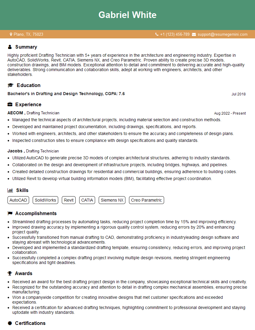
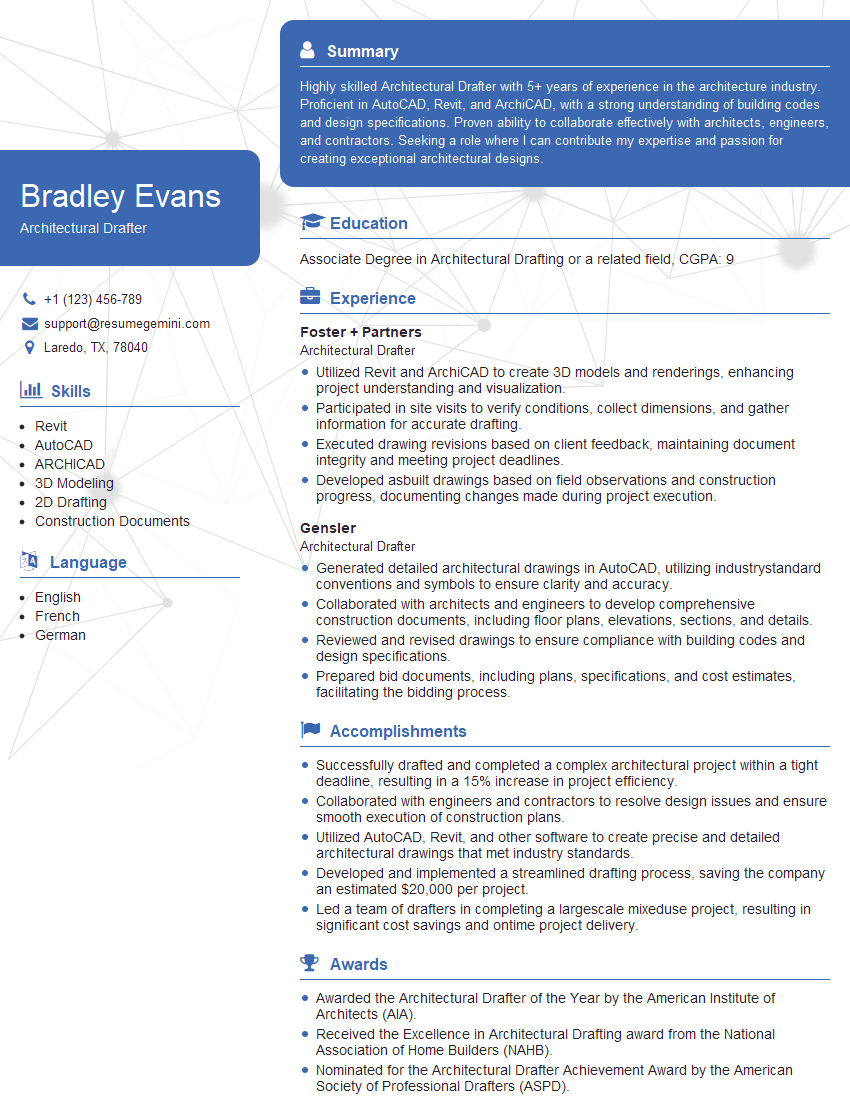
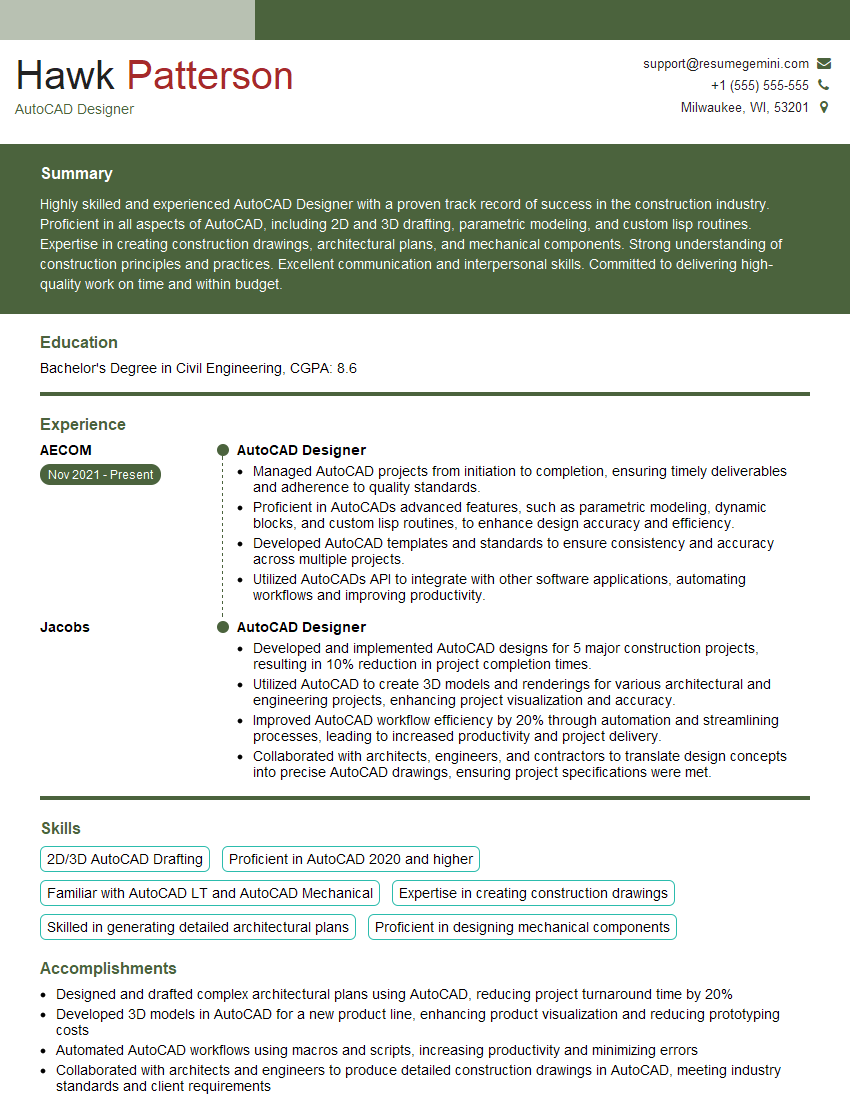
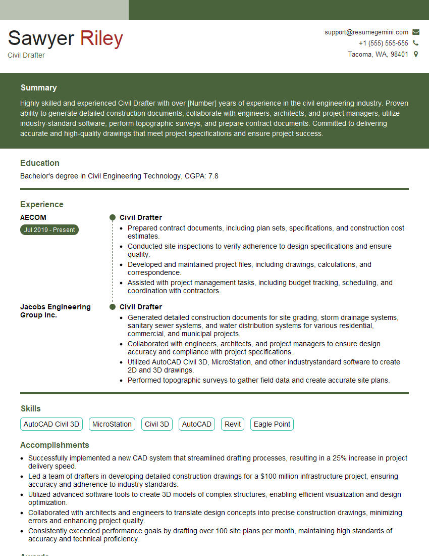
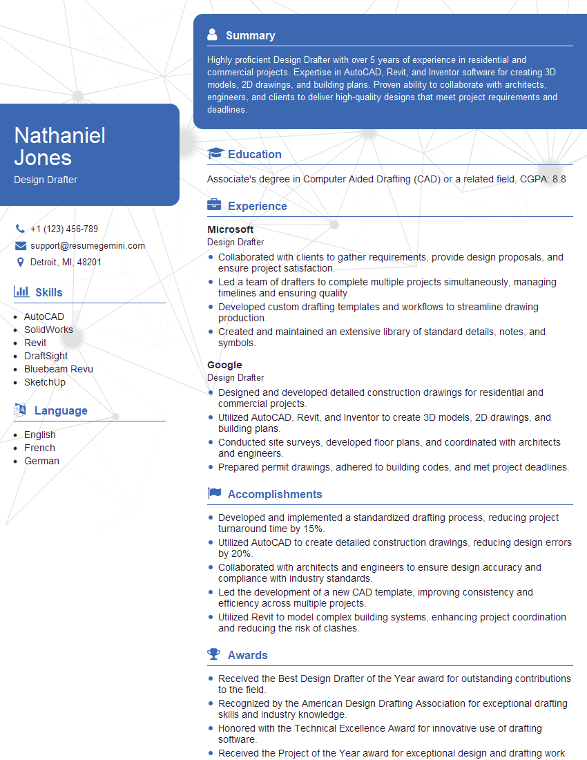
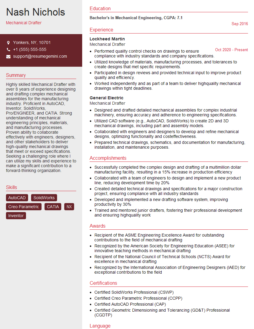
Mastering AutoCAD Drafting opens doors to exciting and rewarding career opportunities in architecture, engineering, and design. To maximize your job prospects, create a strong, ATS-friendly resume that highlights your skills and experience effectively. ResumeGemini is a trusted resource to help you build a professional resume that stands out. We provide examples of resumes tailored to AutoCAD Drafting to help guide your creation process, ensuring your qualifications are presented in the best possible light.
Explore more articles
Users Rating of Our Blogs
Share Your Experience
We value your feedback! Please rate our content and share your thoughts (optional).
What Readers Say About Our Blog
Hello,
We found issues with your domain’s email setup that may be sending your messages to spam or blocking them completely. InboxShield Mini shows you how to fix it in minutes — no tech skills required.
Scan your domain now for details: https://inboxshield-mini.com/
— Adam @ InboxShield Mini
Reply STOP to unsubscribe
Hi, are you owner of interviewgemini.com? What if I told you I could help you find extra time in your schedule, reconnect with leads you didn’t even realize you missed, and bring in more “I want to work with you” conversations, without increasing your ad spend or hiring a full-time employee?
All with a flexible, budget-friendly service that could easily pay for itself. Sounds good?
Would it be nice to jump on a quick 10-minute call so I can show you exactly how we make this work?
Best,
Hapei
Marketing Director
Hey, I know you’re the owner of interviewgemini.com. I’ll be quick.
Fundraising for your business is tough and time-consuming. We make it easier by guaranteeing two private investor meetings each month, for six months. No demos, no pitch events – just direct introductions to active investors matched to your startup.
If youR17;re raising, this could help you build real momentum. Want me to send more info?
Hi, I represent an SEO company that specialises in getting you AI citations and higher rankings on Google. I’d like to offer you a 100% free SEO audit for your website. Would you be interested?
Hi, I represent an SEO company that specialises in getting you AI citations and higher rankings on Google. I’d like to offer you a 100% free SEO audit for your website. Would you be interested?
good
