Every successful interview starts with knowing what to expect. In this blog, we’ll take you through the top 2D Drafting (AutoCAD, AutoCAD LT) interview questions, breaking them down with expert tips to help you deliver impactful answers. Step into your next interview fully prepared and ready to succeed.
Questions Asked in 2D Drafting (AutoCAD, AutoCAD LT) Interview
Q 1. Explain the difference between AutoCAD and AutoCAD LT.
AutoCAD and AutoCAD LT are both 2D drafting software from Autodesk, but they cater to different needs. Think of it like this: AutoCAD is the fully loaded, luxury car, while AutoCAD LT is the reliable, economical sedan. AutoCAD offers a significantly broader range of features, including advanced 3D modeling capabilities, automation tools (AutoLISP, VBA), and extensive customization options. AutoCAD LT, on the other hand, focuses on the core 2D drafting functionalities. It’s perfect for simpler projects where the advanced features of AutoCAD aren’t necessary. The key difference boils down to feature set and cost; AutoCAD LT is a more budget-friendly option, but sacrifices some power and flexibility.
For instance, if you’re a professional architect designing a complex building, AutoCAD’s powerful features would be invaluable. But if you’re a small business owner creating simple floor plans, AutoCAD LT might be perfectly sufficient and more cost-effective.
Q 2. Describe your experience with various AutoCAD commands (e.g., LINE, CIRCLE, ARC, COPY, MOVE, MIRROR).
I’m highly proficient in a wide array of AutoCAD commands. My daily workflow heavily utilizes commands like LINE, CIRCLE, ARC for creating basic geometric shapes. COPY and MOVE are essential for efficient duplication and repositioning of objects, while MIRROR is crucial for creating symmetrical elements. I frequently use these commands in conjunction with object snaps (like endpoint, midpoint, intersection) for precise drafting. For example, when drawing a building’s footprint, I’d use LINE to define the walls, ARC for rounded corners, and COPY to quickly create identical windows or doors. I often leverage the OFFSET command to create parallel lines for things like walls and boundaries.
Beyond the basics, I’m also experienced with commands like TRIM, EXTEND, ERASE for cleaning up drawings, ARRAY for creating repetitive patterns, and SCALE for resizing objects proportionately. Mastering these commands allows for significant time savings and increased accuracy in my designs.
Q 3. How do you manage layers and layer properties in AutoCAD?
Layer management is fundamental to organizing and controlling the complexity of any AutoCAD drawing. Think of layers as transparent sheets stacked on top of each other. Each layer can hold different types of objects (walls on one layer, doors on another, etc.). This allows for selective visibility, modification, and printing. I manage layers through the Layer Properties Manager, where I can create new layers, rename them, assign colors and linetypes, and control their visibility and plotting properties. For instance, I might create a layer called “Walls” with a thick red line type, a layer called “Doors” with a black line type, and a layer called “Dimensions” that’s only visible when I’m reviewing the dimensions. Using layers efficiently makes a drawing much easier to manage and understand, particularly in complex projects.
Furthermore, I utilize layer states (freezing, thawing, turning on/off) to streamline my workflow. Freezing unnecessary layers speeds up display performance, especially when working with large, intricate drawings. Proper layer management is critical for collaboration, allowing different team members to work on specific aspects of a drawing without interfering with each other’s work.
Q 4. What are blocks and how do you create and use them?
Blocks are essentially reusable components within an AutoCAD drawing. Imagine them as pre-fabricated modules. They allow you to create a symbol or group of objects once and then insert multiple instances of that symbol throughout your drawing. This saves tremendous time and effort, especially when working with repetitive elements. Creating a block involves selecting the objects you want to include, then using the BLOCK command to define the block. You assign it a name and can even add attributes (like text fields for labeling) to make it more dynamic. Once created, the block can be inserted and manipulated easily.
I frequently use blocks for things like standard door symbols, window types, plumbing fixtures, or even entire room modules. This not only speeds up the design process but also ensures consistency and accuracy throughout the drawing. For example, I might create a block for a specific type of door and then reuse it throughout the building’s floor plan. This ensures consistency in design and makes editing and updating easier if a design change is required.
Q 5. Explain your experience with dimensioning and annotation in AutoCAD.
Dimensioning and annotation are crucial for conveying the precise measurements and other important information within a drawing. I’m experienced with creating various dimension types, including linear, angular, radial, and diameter dimensions. I utilize AutoCAD’s dimension styles to ensure consistency in the appearance of dimensions across the drawing. I understand the importance of creating clear, unambiguous annotations, and I pay careful attention to dimension placement to avoid clutter and improve readability. For complex drawings, I often use annotation scales to ensure dimensions are displayed correctly regardless of the drawing’s overall scale.
Beyond basic dimensions, I also have experience with adding text-based annotations, leaders, and callouts to highlight specific details or provide additional information. Accurate dimensioning is vital to ensure that the design is built correctly, so it’s a skill that demands precision and attention to detail.
Q 6. How do you create and modify text styles in AutoCAD?
Creating and modifying text styles in AutoCAD allows you to control the appearance of text within your drawings. This includes font type, font size, height, color, and other attributes. To create a new text style, you access the Text Style Manager. You’ll then define the font, height, width factor, and other properties as needed. These styles are then easily applied to any text you add in your drawings.
I often create multiple text styles to ensure consistency and readability. For example, I might have one style for dimensions (smaller, simpler font), another for titles (larger, bolder font), and a third for general notes (a more readable standard font). This improves the overall clarity and professionalism of my drawings, making them easier to understand and interpret.
Q 7. How familiar are you with different plotting configurations and output settings?
I possess extensive experience with various plotting configurations and output settings in AutoCAD. This includes selecting the correct plotter or printer, defining the paper size, orientation (portrait or landscape), and scale. I’m familiar with adjusting plot styles to control the way different layers and objects are represented in the final output. I know how to create and manage plot style tables (PSTs) to customize the appearance of plotted drawings. For example, I might create separate plot styles for different types of drawings, or even for different phases of a project, ensuring the drawings always have the correct line weights and colors.
Beyond the basics, I’m also comfortable with advanced plotting options, such as defining plot areas, adjusting margins, and managing page setups for multi-sheet drawings. Understanding these settings ensures the plotted drawings are clear, accurate, and meet any project-specific requirements, whether it’s printing to a large-format plotter for construction documents or creating a PDF for review.
Q 8. Describe your process for creating and managing drawing templates.
Creating and managing drawing templates in AutoCAD is crucial for maintaining consistency and efficiency across projects. My process begins with identifying the common elements needed in most drawings – things like title blocks, layers, text styles, and linetypes. I then create a new drawing and meticulously set up these elements. Think of a template as a pre-built foundation for a house; it saves you from starting from scratch each time.
Layer Setup: I establish a clear layer structure with appropriate names and colors, ensuring logical grouping for different object types (e.g., ‘Walls’, ‘Doors’, ‘Plumbing’). This improves organization and simplifies selection.
Title Block Creation: I design a comprehensive title block including fields for project name, date, scale, revision, and client information. Using attributes allows for easy updating of this information across multiple drawings.
Text Styles: I define standard text styles for different purposes, including annotations, dimensions, and titles, ensuring consistent font, size, and height. For example, I might have separate styles for notes (smaller font) and dimensions (bold font).
Linetypes: I establish standard linetypes for centerlines, hidden lines, and other elements to enhance drawing clarity.
Saving the Template: Finally, I save the drawing as a template file (with the .dwt extension) in a readily accessible location. This makes it easily reusable across different projects.
Regularly reviewing and updating my templates is key to maintaining their effectiveness and reflecting the latest standards and best practices. For example, if our company changes its title block format, I’d update the template accordingly.
Q 9. What are your preferred methods for creating and editing complex geometries?
Creating and editing complex geometries in AutoCAD relies on a combination of tools and techniques. My approach prioritizes accuracy and efficiency.
Precise Input Methods: I utilize object snaps (endpoint, midpoint, intersection, etc.) and precise coordinate entry to ensure accurate geometry creation. This minimizes the need for later corrections and ensures dimensional accuracy.
Dynamic Input: I use dynamic input extensively to see the dimensions and coordinates of objects as I draw, providing real-time feedback and reducing the need for constant switching between the command line and the drawing area.
Arrays and Blocks: For repetitive elements, I create blocks and use arrays to easily create multiple instances. This not only saves time but also ensures consistency in geometry.
Boolean Operations: For more complex shapes, I leverage Boolean operations (Union, Subtract, Intersect) to combine or modify existing geometry. Imagine needing to cut a hole in a wall; Boolean subtraction is the perfect tool for this.
Parametric Modeling: While AutoCAD isn’t explicitly parametric, I use constraints (where applicable) and variables (through VBA or other scripting) to create more adaptable and less error-prone geometry. This is especially helpful when design changes are frequently required.
For instance, when designing a complex building facade, I would first create individual components as blocks. Then, using arrays and Boolean operations, I would assemble them into the final design. Regularly checking dimensions using the distance command and verifying alignment prevents accumulation of small errors.
Q 10. Explain your experience with external references (xrefs).
External References (xrefs) are essential for managing large projects and collaborating with multiple team members. My experience includes both attaching and managing xrefs effectively.
Attaching Xrefs: I know how to attach both DWG and DXF files as xrefs, choosing between attaching them as an overlay (affecting the display but not the data within the host file) or as a reference (linking the data). The choice depends on the needs of the project – if edits in the referenced file need to be reflected in the host file, referencing is necessary.
Managing Xrefs: I’m proficient in managing xref paths, binding xrefs (incorporating them into the host drawing), and updating xrefs to reflect changes in the source files. This is key for keeping project drawings synchronized.
Nested Xrefs: I have experience working with nested xrefs (xrefs within xrefs) and managing the potential complexity associated with them. This requires careful planning and clear naming conventions to avoid confusion.
Xref Overlays: I know how to use xref overlays to visualize multiple versions or options of a design without modifying the original drawings.
In a typical project, I might use xrefs to incorporate structural drawings created by a separate team into my architectural drawings. This avoids redundancy and ensures consistency across disciplines.
Q 11. How do you handle large AutoCAD files efficiently?
Handling large AutoCAD files efficiently requires a multi-pronged approach. Speed and stability are crucial.
Purge and Audit: Regularly purging unused blocks, layers, and other objects and auditing the drawing to identify and repair errors are essential for reducing file size and improving performance. It’s like decluttering a house; removing unnecessary items improves space and accessibility.
Layer Management: Maintaining a well-organized layer structure and freezing or turning off layers that are not currently needed significantly speeds up drawing navigation and regeneration.
Xrefs vs. Linking: Using external references (xrefs) instead of embedding objects or drawings greatly reduces the size of the main file.
Object Selection: Using efficient selection methods such as window selection or fence selection instead of individual object selection speeds up editing tasks. This is especially beneficial when dealing with densely populated drawings.
High-Performance Workstations: Working with a workstation equipped with sufficient RAM and processing power is vital for large files.
Regular Saves and Backups: Frequent saving and maintaining regular backups prevent data loss and ensure that work isn’t lost due to unexpected crashes.
A strategy I implement involves regularly purging and auditing files, especially after major design changes, maintaining a streamlined layer structure and utilizing xrefs. This proactive maintenance prevents the file from growing uncontrollably.
Q 12. Describe your experience with creating and editing tables within AutoCAD.
Creating and editing tables in AutoCAD is straightforward yet powerful. I regularly use this functionality for scheduling, material lists, and other tabular data.
Table Creation: I’m proficient in creating tables using the TABLE command, specifying the number of rows and columns, and defining cell properties (text height, alignment, etc.).
Data Entry and Editing: I can easily edit cell contents, add or delete rows and columns, and format the table for clarity and readability. I can also use formulas within tables for simple calculations, such as summing values.
Linking to External Data: I can link tables to external spreadsheet data (Excel), allowing for automatic updates as the data source changes. This is particularly beneficial for dynamically updating schedules and reports.
Table Styles: I understand how to utilize table styles to maintain consistent formatting and appearance across multiple tables in a drawing. This enhances the professional look of the documents.
For example, when creating a door schedule, I’d use a table to list door numbers, types, sizes, and locations. Linking this table to an external spreadsheet allows for easy updates if design changes necessitate revisions.
Q 13. What are some common troubleshooting techniques you use in AutoCAD?
Troubleshooting in AutoCAD involves a systematic approach. My techniques prioritize identifying the root cause efficiently.
Check Layer States: Often, objects are not visible because their layer is frozen, off, or has a very faint color. Verifying layer states is frequently the first step.
Examine Object Properties: Checking object properties (such as linetype, color, and layer) can reveal why an object is not behaving as expected.
Regenerate and Zoom Extents: A simple regenerate and zoom extents command often resolves display glitches and unexpected behavior. This refreshes the display and ensures all objects are visible within the current viewport.
Check for Circular References: If problems arise when working with xrefs, it is important to check for any circular references (where two or more files refer to each other), which can lead to regeneration errors.
Use the AutoCAD Help System: The built-in help system provides comprehensive information on commands, error messages, and troubleshooting techniques.
Consult Online Resources and Forums: If I am unable to find a solution, the vast online community can offer helpful insights and workarounds for various AutoCAD problems.
For example, if a dimension is not showing up, I’d first check if the dimension layer is frozen or off. Then, I’d check the dimension’s properties to make sure it hasn’t been accidentally turned off. If that doesn’t work, I’d consider whether a corrupted object or a circular reference might be the issue.
Q 14. How do you ensure accuracy and precision in your drawings?
Ensuring accuracy and precision in AutoCAD drawings requires meticulous attention to detail and consistent application of best practices.
Object Snaps: Consistent use of object snaps (endpoint, midpoint, intersection, etc.) eliminates guesswork and ensures accurate placement of objects.
Precise Coordinate Entry: Using precise coordinate input (e.g., 10.5, 25.25) for defining points and objects avoids approximation and ensures geometric accuracy.
Dimensioning Techniques: Applying proper dimensioning standards and techniques ensures that the drawings clearly communicate the exact dimensions of all elements. This includes consistent dimension styles and appropriate tolerances.
Regular Verification: Regularly checking dimensions and geometry using the distance and area commands, as well as visual inspection, helps detect and correct errors early on.
Utilize Constraints (Where Available): While AutoCAD lacks full parametric capabilities, using available constraints (especially in newer versions) helps maintain geometric relationships and prevents errors during design modifications.
Use of Design Standards and Templates: Following design standards and using well-maintained templates promotes consistency and accuracy across the project.
Accuracy is paramount, especially in construction drawings. A small error in a dimension can lead to costly mistakes during construction. My systematic approach ensures that such errors are minimized, leading to reliable and accurate documentation.
Q 15. Explain your experience with using AutoCAD’s dynamic input feature.
AutoCAD’s dynamic input is a powerful feature that allows you to enter commands and coordinates directly at the cursor, eliminating the need to constantly switch between the command line and the drawing area. It significantly speeds up the drafting process and improves workflow efficiency. Think of it as having a mini-command line following your cursor.
For instance, when drawing a line, instead of typing ‘LINE’ in the command line and then specifying coordinates separately, dynamic input lets you simply click your starting point, then hover your cursor to the desired endpoint. The distance and angle are displayed dynamically, and you can directly type the required distance or angle (e.g., @5,3 for a line 5 units along X and 3 along Y) or even use polar coordinates (e.g., 10<45 for a line 10 units long at 45 degrees). This eliminates repetitive typing and allows for precise and intuitive drawing.
I extensively use dynamic input for all line, arc, circle, and other geometric constructions. It’s invaluable when creating detailed drawings quickly and accurately. I regularly fine-tune its settings to display the information that best suits my workflow. For example, I often choose to display both Cartesian and polar coordinates simultaneously.
Career Expert Tips:
- Ace those interviews! Prepare effectively by reviewing the Top 50 Most Common Interview Questions on ResumeGemini.
- Navigate your job search with confidence! Explore a wide range of Career Tips on ResumeGemini. Learn about common challenges and recommendations to overcome them.
- Craft the perfect resume! Master the Art of Resume Writing with ResumeGemini’s guide. Showcase your unique qualifications and achievements effectively.
- Don’t miss out on holiday savings! Build your dream resume with ResumeGemini’s ATS optimized templates.
Q 16. How familiar are you with AutoCAD’s customization options?
AutoCAD’s customization options are incredibly extensive, allowing for a high degree of personalization to tailor the software to individual workflows and project requirements. I’ve leveraged these options extensively to optimize my efficiency and consistency.
- Customizing toolbars and menus: I’ve created custom toolbars grouping frequently used commands, enhancing accessibility and speed. This minimizes the need to navigate through menus, making my process smoother. For example, I have a toolbar specifically for annotation tools, streamlining text and dimensioning.
- Creating and using custom linetypes and text styles: Maintaining consistency in a drawing is crucial, especially in large projects. I create custom linetypes and text styles to ensure uniformity across all my drawings, following company or project-specific standards.
- AutoLISP and VBA scripting: Although I haven’t used AutoLISP extensively, my experience includes basic scripting for automating repetitive tasks, like creating custom hatches or generating reports, to significantly improve efficiency and reduce error.
- CUI (Custom User Interface): I have used the CUI editor to completely change the layout and even create custom palettes if I’m working on something very specific that requires a unique approach.
Essentially, I treat customization as an essential part of my workflow, ensuring the software optimally fits my needs and the project’s requirements. It’s not just about making the software ‘look’ a certain way but about enhancing efficiency and accuracy.
Q 17. Describe your process for creating detailed drawings from sketches or conceptual designs.
My process for creating detailed drawings from sketches or conceptual designs involves several key steps, starting with digitization and progressing towards refinement and finalization.
- Digitization: I begin by scanning or taking high-resolution photos of the sketches or designs. If it’s a digital sketch, I import it directly.
- Tracing and scaling: I use AutoCAD’s tracing tools to accurately recreate the sketch’s geometry in CAD. I carefully check the scales and make adjustments as needed to maintain proportions.
- Dimensioning and annotation: Once the geometry is finalized, I add dimensions and other annotations (notes, labels, etc.) to comply with the project’s specifications and standards. I meticulously review these for accuracy and completeness.
- Layer management: I create multiple layers to organize different elements (e.g., geometry, dimensions, text). This enhances clarity, organization, and control throughout the design process.
- Refinement and detail: I iterate and refine the drawing until it meets the required level of detail and accuracy. I may add more detailed elements, adjust dimensions or improve clarity of annotations.
- Checking and reviewing: Before finalizing the drawing, I perform thorough checks for errors, inconsistencies, and omissions. This often involves using various checking and plotting tools to look for issues.
This structured approach ensures accuracy and allows for easy collaboration and revision.
Q 18. How do you manage revisions and version control in your drawings?
Managing revisions and version control is critical for any large project, and I employ several strategies to maintain drawing integrity and track changes effectively.
- AutoCAD’s Xrefs: For large or collaborative projects, I utilize external references (Xrefs) to manage different parts of a drawing separately. This allows multiple team members to work on different sections concurrently without overwriting each other’s work.
- Save As: I regularly save my work using a clear naming convention that incorporates date and revision number (e.g., ‘Drawing_Name_Rev_A.dwg’, ‘Drawing_Name_Rev_B.dwg’). This helps maintain a clear history of revisions.
- Plot stamps: I include plot stamps that automatically display the drawing’s revision number, date, and other relevant details on each plot, ensuring that the output is properly documented.
- Cloud-based solutions: I utilize cloud-based solutions like Autodesk’s BIM 360 or other similar platforms for managing and version-controlling drawings in collaborative projects, enhancing accessibility and facilitating teamwork.
Combining these methods ensures clear documentation and easy tracking of changes throughout the project’s lifecycle.
Q 19. What are your preferred methods for sharing and collaborating on AutoCAD drawings?
Sharing and collaborating on AutoCAD drawings involves choosing methods that optimize both efficiency and data security. My preferred methods depend largely on the project and team size.
- Cloud-based collaboration platforms: For larger projects and teams, I rely on cloud-based platforms like BIM 360 Docs, A360, or similar solutions. These facilitate simultaneous access, version control, and real-time collaboration features.
- Emailing DWG files: For smaller projects and simple file sharing, sending DWG files directly via email is a straightforward method, although it’s less efficient for larger projects or frequent updates.
- Network folders: For project teams working within the same network environment, sharing files through network folders is a convenient way to collaborate, enabling seamless access and version management using the file system itself.
- PDF exports: For sharing final versions with clients or stakeholders who may not have AutoCAD, exporting to PDF is a reliable option, ensuring compatibility and preserving the drawing’s visual integrity.
The most suitable method always depends on the project’s complexity, the number of collaborators, and the necessary level of data security.
Q 20. How familiar are you with AutoCAD’s object snap tools?
AutoCAD’s object snap tools are essential for precise and efficient drafting. These tools allow you to easily snap to specific points on existing objects, ensuring accuracy and consistency. Think of them as incredibly helpful guides that ensure perfect alignment and avoid guesswork.
I routinely use object snaps such as:
- Endpoint: Snaps to the endpoint of a line or object.
- Midpoint: Snaps to the midpoint of a line or object.
- Center: Snaps to the center point of a circle or arc.
- Intersection: Snaps to the intersection point of two objects.
- Quadrant: Snaps to a quadrant point on a circle or arc.
- Node: Snaps to a point object.
Combining object snaps with dynamic input provides an exceptionally powerful combination for precise and quick drawing. For example, I might use the midpoint object snap in combination with dynamic input to quickly bisect a line, or the intersection object snap with polar coordinates to draw a line precisely from the intersection of two curves at a specific angle and distance.
My proficiency in object snaps allows me to create accurate and complex drawings efficiently, minimizing the need for manual measurements and adjustments.
Q 21. Describe your experience with different file formats used in AutoCAD (e.g., DWG, DXF).
AutoCAD uses various file formats, each with its own strengths and weaknesses. Understanding these differences is key to effective file management and collaboration.
- DWG (Drawing): This is the native file format of AutoCAD. It’s a proprietary format that supports the full range of AutoCAD features and data, including layers, blocks, and attributes. This is my primary file format because it preserves all drawing information.
- DXF (Drawing Exchange Format): This is a neutral, text-based file format designed for exchanging drawings between different CAD software packages. It’s less feature-rich than DWG, often losing some formatting information during the conversion process, but useful for sharing with other software applications that might not natively support DWG.
- Other formats: I also frequently use formats such as PDF for sharing with clients or stakeholders who may not have AutoCAD, and other image formats such as JPG, PNG or TIFF for presentations.
My understanding of these different file formats helps me ensure compatibility and data integrity in various project situations. I always carefully consider the intended use of a file before choosing its format, minimizing any potential loss of information or compatibility issues.
Q 22. Explain your experience with using AutoCAD’s coordinate systems.
AutoCAD offers several coordinate systems for precise drawing and object placement. Understanding these is crucial for efficient and accurate drafting. The most common are World Coordinate System (WCS), User Coordinate System (UCS), and Polar Coordinates.
World Coordinate System (WCS): This is the default coordinate system, a fixed three-dimensional system with X, Y, and Z axes. Think of it as the foundational grid for your entire drawing. All objects are initially defined relative to the WCS origin (0,0,0). For example, placing a point at
(10,5,0)in WCS places it 10 units along the X-axis and 5 units along the Y-axis.User Coordinate System (UCS): This allows you to define a new coordinate system oriented however you need. Imagine you’re drawing a house; you might create a UCS aligned with the front face of the house, making it easier to place windows and doors. You can rotate, move, and even save different UCS orientations for reuse in complex projects. The command
UCSoffers various options like creating a UCS based on three points, an object, or even a view.Polar Coordinates: These specify a point’s location using a distance and an angle from a reference point. For instance,
@5<10places a point 5 units away from the current point, at a 10-degree angle. This is exceptionally useful for creating circles, arcs, and other geometric shapes easily and precisely.
My experience includes extensive use of all three systems; I frequently switch between them depending on the project's requirements. For example, when designing a complex mechanical part, I'll use UCS extensively to align the coordinate system with specific features of the part for easier dimensioning and object placement.
Q 23. How do you create and use named views in AutoCAD?
Named views are a powerful tool in AutoCAD for saving and quickly recalling specific viewpoints of your drawing. They’re particularly beneficial in large, complex projects or when collaborating with others. Imagine working on a building plan; you might need to quickly switch between views of the floor plan, elevations, and sections. Named views make this incredibly easy.
Creating a named view involves selecting the desired viewport and using the VIEW command. You assign a descriptive name (e.g., 'North Elevation', 'Floor Plan'), and AutoCAD saves the zoom level, pan position, and any other viewport settings. To recall a view, simply select it from the list using the same command.
I regularly utilize named views to streamline my workflow. For example, in a landscape design project, I created named views for each individual garden bed, saving different zoom levels and display settings for each.
Q 24. Describe your experience with creating and managing external references (xrefs).
External references (xrefs) are crucial for managing large and complex projects efficiently, allowing you to link external drawings into your current drawing. This is like including a pre-designed module in your main design.
My experience involves both attaching and overlaying xrefs. Attaching links the xref to the main drawing, updating automatically when the external file changes. Overlaying places the xref on top, as a visual reference, without linking. I often use xrefs to incorporate standard details or components, such as door schedules or electrical symbols, from a library of drawings. This maintains consistency and simplifies revisions.
Managing xrefs involves understanding how to bind, detach, and reload them. Binding essentially makes the xref a permanent part of your drawing; detaching removes it; and reloading updates the xref to reflect any changes in the external file. I carefully manage xref paths to avoid broken links and ensure smooth collaboration among team members. Proper naming and organization are crucial to maintain control over a project with multiple xrefs.
Q 25. How familiar are you with the use of linetypes and text styles?
Linetypes and text styles are essential for improving drawing clarity and consistency. Linetypes control the visual representation of lines (e.g., dashed, dotted, continuous) while text styles define the font, size, and other attributes of text.
I frequently use linetypes to distinguish different elements in a drawing; for instance, I might use dashed lines for centerlines and continuous lines for building outlines. I regularly create custom linetypes to meet specific project needs, like creating a linetype representing a specific type of pipe.
Similarly, I utilize text styles to maintain uniformity and readability. I'll often create distinct styles for dimensions, notes, and titles, ensuring consistent font sizes, weights, and heights throughout the drawing. This dramatically improves the overall quality and professionalism of the final product. My understanding extends to managing and organizing linetype and text style libraries for easy access and reuse.
Q 26. Explain your experience with AutoCAD's drawing cleanup tools.
AutoCAD offers several powerful cleanup tools to improve drawing performance and clarity. These tools are essential for maintaining organized and efficient drawings, particularly in large projects where minor inconsistencies can accumulate.
My experience includes extensive use of commands like PURGE (to remove unused blocks, layers, and styles), OVERKILL (to remove duplicate lines and objects), and AUDIT (to check for and repair drawing errors). I also frequently use the SELECTSIMILAR command to identify and edit similar objects, and I'm proficient in using layer properties to manage object visibility and other attributes.
Drawing cleanup is a crucial part of my workflow, performed regularly to prevent performance issues and maintain drawing integrity. A well-maintained drawing is easier to understand, edit, and collaborate on.
Q 27. How do you ensure that your drawings meet specific industry standards and regulations?
Adherence to industry standards and regulations is paramount in professional drafting. This ensures drawings are accurate, consistent, and comply with legal and safety requirements.
My approach involves understanding the relevant standards for each project (e.g., ANSI, ISO, or client-specific standards). This understanding informs my layer naming conventions, dimensioning styles, and overall drawing organization. I use templates conforming to these standards to start each new drawing. For example, when preparing construction drawings, I strictly adhere to local building codes and relevant industry best practices.
Regularly reviewing drawings against the applicable standards and using tools to check for inconsistencies are crucial steps. I carefully check dimensioning, annotation, and object properties to ensure they align with the specified requirements. Collaboration with other professionals and regular review cycles further guarantee compliance.
Q 28. Describe a challenging 2D drafting project and how you overcame the challenges.
One challenging project involved creating detailed 2D drawings for a complex, multi-story building with intricate architectural features. The challenge stemmed from the need to coordinate various disciplines (architectural, structural, MEP) within a single model, ensuring all drawings were compatible and consistent.
To overcome this, I implemented a robust layer management system, using consistent naming conventions across disciplines. I established clear communication channels with the design team, using xrefs extensively to share and update individual components. Regular coordination meetings helped identify and resolve conflicts early in the process. We used a centralized drawing management system, ensuring everyone worked from the most recent versions. Furthermore, I created detailed annotation and dimensioning schemes to improve clarity. This structured approach ensured the project was completed on time and to the client's specifications.
Key Topics to Learn for 2D Drafting (AutoCAD, AutoCAD LT) Interview
- Drawing Setup and Units: Understanding drawing limits, units, layers, and templates for efficient workflow and project standardization. Practical application: Setting up a drawing for a specific project with accurate scaling and layering for different components.
- Geometry Creation and Manipulation: Mastering the creation and modification of lines, arcs, circles, polylines, and other geometric primitives. Practical application: Accurately drawing complex shapes and objects from specifications or sketches.
- Dimensioning and Annotation: Proficiency in creating clear and precise dimensions, text, and other annotations following industry standards. Practical application: Creating detailed drawings that accurately communicate design intent to others.
- Object Snapping and Constraints: Utilizing object snaps (endpoints, midpoints, intersections, etc.) and constraints to ensure accuracy and precision in drawing. Practical application: Quickly and accurately creating precise geometric relationships between objects.
- Working with Blocks and Xrefs: Understanding the use of blocks for reusable components and external references (Xrefs) for collaborative projects. Practical application: Efficiently managing and updating components within large or complex drawings.
- Layer Management: Effectively organizing layers to manage drawing complexity and improve clarity. Practical application: Maintaining a structured and organized drawing to improve collaboration and prevent errors.
- Plotting and Output: Understanding different plotting configurations and output formats (PDF, DWF, etc.). Practical application: Generating high-quality drawings suitable for various purposes (printing, sharing, archiving).
- AutoCAD/AutoCAD LT Specific Features: Familiarizing yourself with features unique to each software, understanding their strengths and applications. Practical application: Optimizing workflows by leveraging the specific capabilities of the software.
- Problem-Solving and Troubleshooting: Developing strategies for identifying and resolving common drafting challenges. Practical application: Diagnosing and correcting errors efficiently, demonstrating a practical understanding of the software.
Next Steps
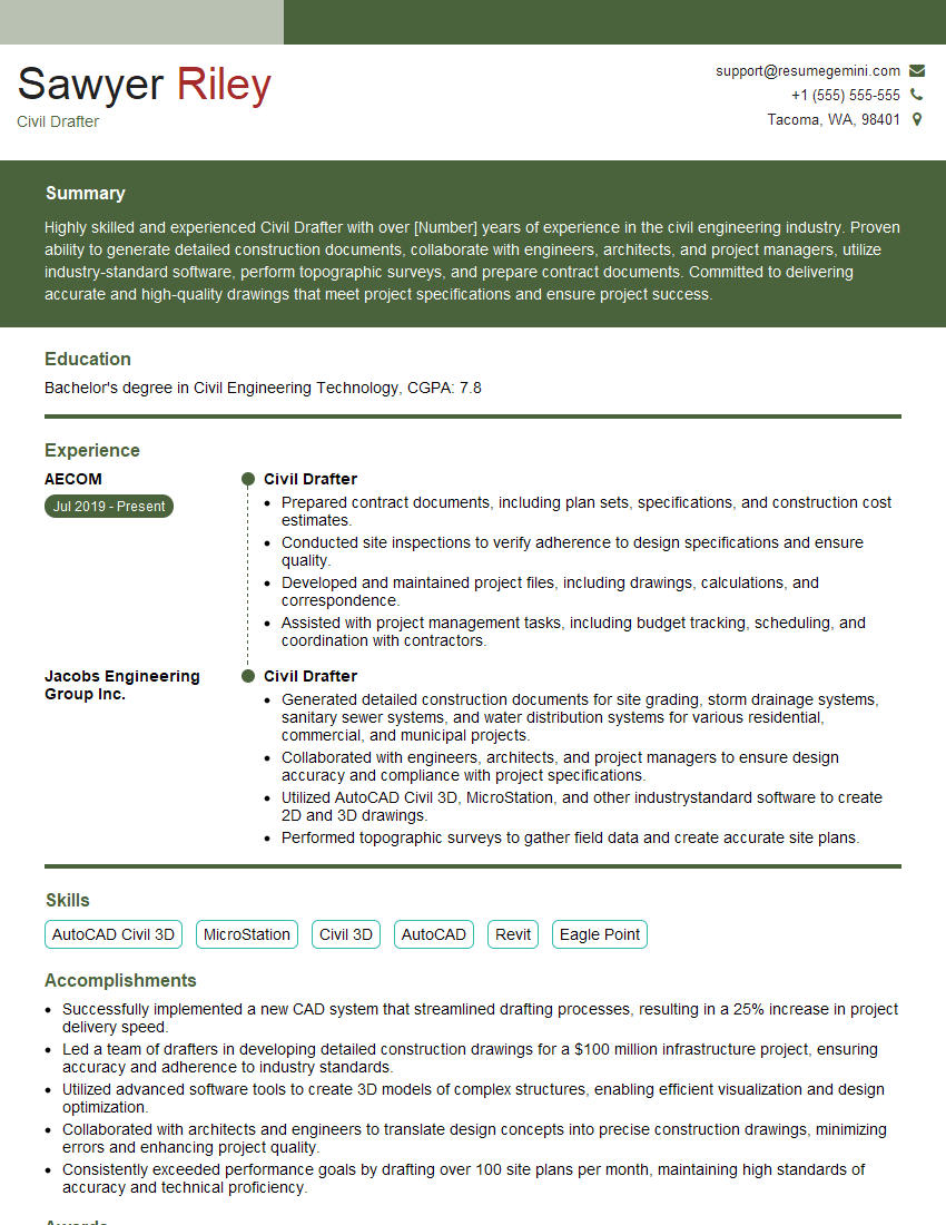
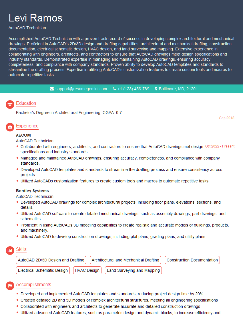
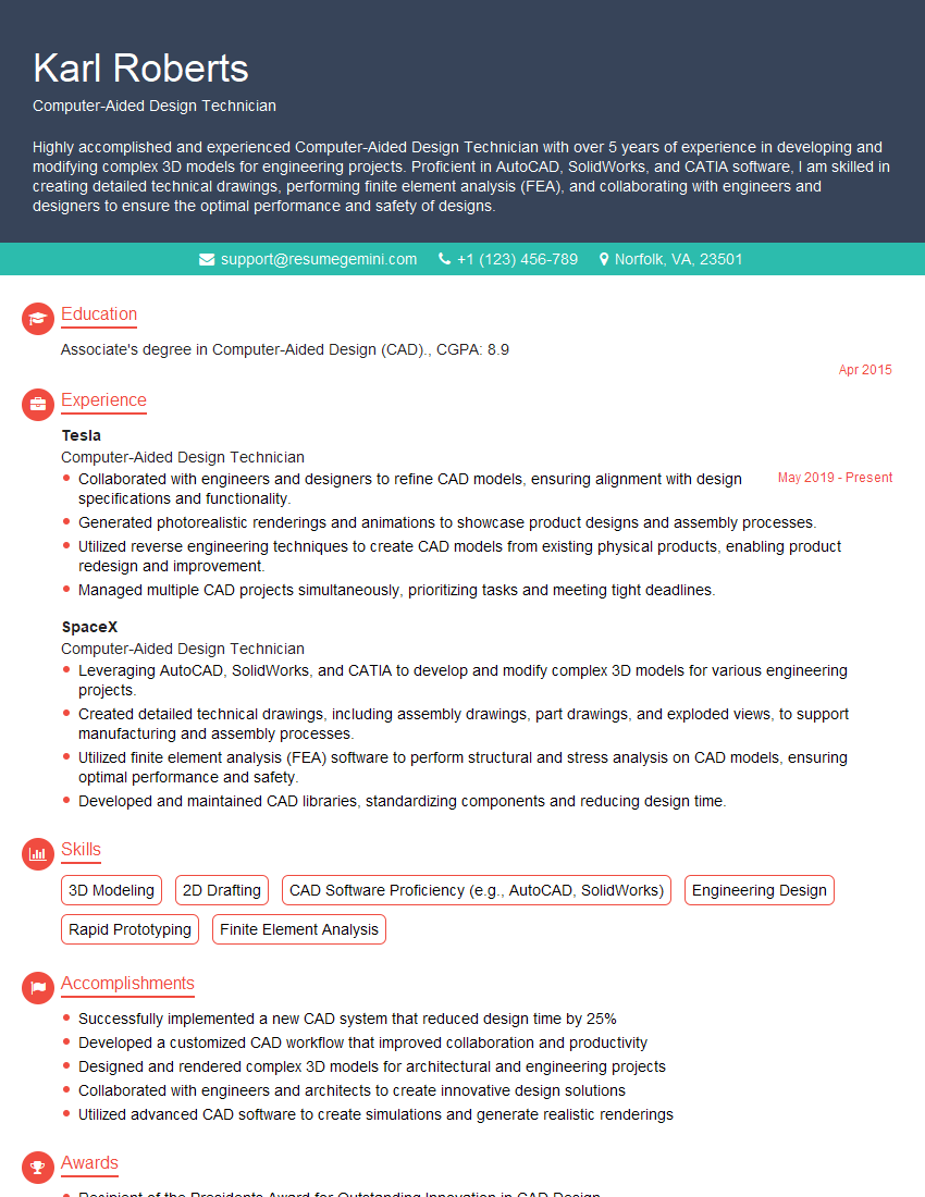
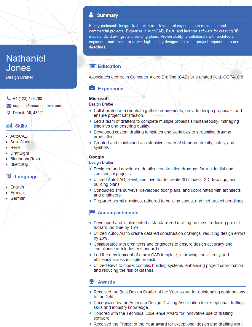
Mastering 2D Drafting with AutoCAD and AutoCAD LT is crucial for a successful career in many fields, opening doors to exciting opportunities in architecture, engineering, and design. To maximize your job prospects, it's vital to create an ATS-friendly resume that highlights your skills and experience effectively. ResumeGemini is a trusted resource to help you build a professional and impactful resume. They provide examples of resumes tailored to 2D Drafting (AutoCAD, AutoCAD LT) professionals, giving you a head start in crafting a compelling application.
Explore more articles
Users Rating of Our Blogs
Share Your Experience
We value your feedback! Please rate our content and share your thoughts (optional).
What Readers Say About Our Blog
Hello,
We found issues with your domain’s email setup that may be sending your messages to spam or blocking them completely. InboxShield Mini shows you how to fix it in minutes — no tech skills required.
Scan your domain now for details: https://inboxshield-mini.com/
— Adam @ InboxShield Mini
Reply STOP to unsubscribe
Hi, are you owner of interviewgemini.com? What if I told you I could help you find extra time in your schedule, reconnect with leads you didn’t even realize you missed, and bring in more “I want to work with you” conversations, without increasing your ad spend or hiring a full-time employee?
All with a flexible, budget-friendly service that could easily pay for itself. Sounds good?
Would it be nice to jump on a quick 10-minute call so I can show you exactly how we make this work?
Best,
Hapei
Marketing Director
Hey, I know you’re the owner of interviewgemini.com. I’ll be quick.
Fundraising for your business is tough and time-consuming. We make it easier by guaranteeing two private investor meetings each month, for six months. No demos, no pitch events – just direct introductions to active investors matched to your startup.
If youR17;re raising, this could help you build real momentum. Want me to send more info?
Hi, I represent an SEO company that specialises in getting you AI citations and higher rankings on Google. I’d like to offer you a 100% free SEO audit for your website. Would you be interested?
Hi, I represent an SEO company that specialises in getting you AI citations and higher rankings on Google. I’d like to offer you a 100% free SEO audit for your website. Would you be interested?
good
