The thought of an interview can be nerve-wracking, but the right preparation can make all the difference. Explore this comprehensive guide to 3D Modeling (SolidWorks, AutoCAD Inventor) interview questions and gain the confidence you need to showcase your abilities and secure the role.
Questions Asked in 3D Modeling (SolidWorks, AutoCAD Inventor) Interview
Q 1. Explain the difference between a solid model and a surface model.
The core difference between solid and surface models lies in their representation of geometry. A solid model defines a three-dimensional volume with mass and physical properties. Think of it like a completely sculpted block of clay – it has a defined inside and outside. Solid models are essential for tasks like finite element analysis (FEA) and manufacturing because they represent the physical object accurately.
Conversely, a surface model only defines the exterior surfaces of an object. It’s like a detailed shell; there’s no inherent volume or mass. Surface models are often visually striking, excellent for rendering and visualizations, but unsuitable for engineering analysis that requires volume data. Imagine a high-resolution 3D-scanned model of a human face: it shows the surface details perfectly, but it doesn’t represent the internal structure or density.
In practice, I often use solid modeling for functional designs intended for manufacturing, such as designing a car engine component, while surface modeling is better suited for creating realistic visualizations of products, like the exterior of a car itself, before committing to the final design details. The choice depends entirely on the project’s goals.
Q 2. Describe your experience with SolidWorks’ FeatureManager Design Tree.
The FeatureManager Design Tree in SolidWorks is my indispensable organizational tool. It’s essentially a hierarchical representation of all the features used to construct a part. Each feature, whether it’s an extrusion, a hole, or a revolved surface, is listed chronologically, making it incredibly easy to understand the design’s evolution. Imagine it like a recipe for the 3D model – each step is clearly documented.
My experience with it goes beyond simple navigation. I regularly use it for:
- Editing existing features: I can quickly locate and modify specific features without redrawing the entire part. This is invaluable for iterative design.
- Suppressing and recovering features: This is perfect for exploring different design options without losing previous work. It’s like temporarily turning off elements of the recipe to test a variation.
- Understanding design intent: The tree clearly shows the design’s history, making it easier to diagnose issues or understand decisions made by other designers in a collaborative project.
- Managing large assemblies: By suppressing components in the assembly’s FeatureManager Design Tree, I can significantly improve performance when dealing with complex designs.
For example, if I’m designing a gearbox and realize I need to adjust the size of one of the gears, the FeatureManager Design Tree allows me to go directly to the feature and make the change, quickly and efficiently, ensuring all downstream features automatically update.
Q 3. How do you manage large assemblies in SolidWorks?
Managing large assemblies in SolidWorks requires a strategic approach. Simply opening a massive assembly with thousands of components can easily crash even the most powerful computers. My approach combines several key strategies:
- Component simplification: I leverage SolidWorks’ capabilities to create simplified representations of components. For instance, I might replace detailed models with lightweight placeholders for parts that aren’t critical for the current design phase. This is akin to using a sketch to plan a room layout before detailing the interior design.
- Sub-assemblies: I break down complex assemblies into smaller, more manageable sub-assemblies. This modular approach greatly speeds up loading times and makes it easier to work on specific areas. Think of building a house – you wouldn’t assemble the entire thing at once; you’d build walls, roof, etc., separately before combining them.
- Lightweight components: SolidWorks allows for the creation of lightweight components, reducing file size without sacrificing visual representation. This helps drastically improve performance and responsiveness.
- Performance settings: Optimizing SolidWorks’ performance settings, such as graphics and display, can significantly improve the response time when working with large assemblies.
- Large Design Review: I often utilize SolidWorks’ Large Design Review feature to visualize and manipulate large assemblies without the overhead of full model loading, which is crucial for collaboration and design reviews.
By utilizing a combination of these techniques, I can efficiently manage even the most complex assemblies, ensuring smooth workflow and collaboration.
Q 4. What are your preferred methods for creating complex curves in Inventor?
Inventor offers a robust suite of tools for creating complex curves. My preferred methods depend on the type of curve needed. For precise control, I often use the spline tool, defining points and tangents for the most accurate shape. It’s like sketching a curve freehand, but with the precision of a computer.
For curves based on existing geometry, the projection command is a time-saver. I can project a curve onto a surface, creating a complex curve that follows the underlying geometry. Imagine tracing a path on a curved surface; this tool automatically generates the projected curve.
When dealing with sweeps or lofts, guide curves and sections are essential. Guide curves define the path of the sweep, while sections define the cross-sectional shape, allowing for the creation of intricately curved shapes, like designing the body of a car or airplane.
Finally, for more organic shapes, the freeform tools offer considerable flexibility. Using these tools requires practice to control the shape precisely, but they allow for very natural curves, similar to sculpting with digital clay.
The choice of method always depends on the specific design requirements; for instance, constructing a cam profile requires a high level of precision, so I’d use the spline and potentially the equation-driven curve, while designing a futuristic car body might benefit from the freeform tools for a more organic and fluid look.
Q 5. Explain the concept of constraints in 3D modeling.
Constraints in 3D modeling are the digital equivalent of physical constraints in the real world. They define relationships between different parts or features of a model, ensuring dimensional accuracy, assembly integrity, and ease of manipulation. They are the glue that holds a design together.
Examples of common constraints include:
- Mate constraints: These define how parts connect to each other, such as a ‘mate’ constraint between two cylindrical surfaces simulating a bolted joint.
- Geometric constraints: These define relationships like concentricity, parallelism, or perpendicularity between features. For example, ensuring two holes are perfectly aligned.
- Dimensional constraints: These specify exact distances or angles between features, for instance, defining the exact length of a shaft.
Think of building with LEGOs – constraints ensure that pieces fit together correctly and that the final structure is stable. In 3D modeling, constraints guarantee that the design is both functional and dimensionally sound. They are crucial for ensuring that parts fit together, and for simplifying the modeling process by avoiding manual measurements and adjustments.
Q 6. How do you handle design changes in a collaborative environment using SolidWorks/Inventor?
Handling design changes in a collaborative environment using SolidWorks or Inventor requires a well-defined workflow and the use of version control. I typically use a combination of these strategies:
- Version Control Systems: Using a system like SolidWorks PDM or a similar platform allows me to track changes, revert to previous versions, and manage multiple iterations of the design. This provides a detailed history of all modifications made by all team members.
- Clear Communication: Consistent communication amongst team members is paramount. Using dedicated channels for design discussions and updates keeps everyone informed of changes and potential conflicts.
- Design Reviews: Regular design reviews, where the team discusses the design and potential issues, help prevent conflicts and ensure everyone is on the same page. This is particularly critical when managing complex designs.
- SolidWorks/Inventor Collaboration Tools: Both platforms offer built-in features that facilitate collaboration, allowing multiple users to work on the same model simultaneously or review changes seamlessly.
- Detailed Change Logs: I maintain a detailed change log for each revision, explaining the reason for changes, providing context, and making it easy for others to understand the design evolution.
For example, in a project involving a team designing a complex assembly, we might use SolidWorks PDM to manage the design files. Any change made by a team member is automatically tracked, allowing us to revert to older versions if necessary and preventing accidental overwriting of previous work.
Q 7. Describe your experience with different rendering techniques in SolidWorks or Inventor.
My experience with rendering techniques in SolidWorks and Inventor includes both built-in functionalities and external rendering software. SolidWorks offers several rendering options, from basic photorealistic views to more sophisticated options like realistic lighting and shadows.
I’ve used SolidWorks’ PhotoView 360 extensively for creating high-quality renderings for client presentations and marketing materials. This involves optimizing rendering settings to balance quality and render time, such as adjusting the ray tracing quality, lighting, and material properties. Think of it as setting up the perfect lighting and camera angles for a product photoshoot.
While Inventor doesn’t have a dedicated rendering engine as powerful as SolidWorks’ PhotoView 360, I have utilized its rendering capabilities to generate quick, presentable visualizations. In situations requiring photorealistic images or animations, I often export the model to external rendering software such as Keyshot or V-Ray. These programs are specialized for producing exceptional rendering quality, which is crucial for marketing materials or complex visualizations.
For simple renderings, the default settings in both programs often suffice, but for high-quality results, mastering the software’s advanced rendering settings – like tweaking reflection, refraction, and global illumination parameters – is essential for creating images that truly capture the intricacies of the design.
Q 8. How do you create and manage design documentation?
Creating and managing design documentation is crucial for effective communication and collaboration within engineering teams. It ensures everyone is on the same page, reducing errors and improving efficiency. My approach involves a multi-step process:
- SolidWorks/Inventor Native Tools: I leverage the built-in features of SolidWorks and Inventor, such as creating detailed drawings with annotations, generating parts lists (BOMs), and utilizing revision control. For instance, I extensively use SolidWorks’ drawing tools to generate orthographic views, section views, and detailed dimensions, along with balloons and annotations to specify materials and manufacturing processes.
- Data Management Systems (DMS): I utilize a DMS like Windchill or Vault to manage revisions, track changes, and control access to design files. This ensures version control and prevents accidental overwriting of critical design data. For example, using Vault’s workflow, I can manage design reviews and approvals, automatically notifying relevant stakeholders.
- PDF Generation and Markup: I often generate PDFs for distribution and use markup tools (like Adobe Acrobat Pro) for collaborative design reviews and feedback incorporation. This allows for easier communication with clients or other teams who may not have access to CAD software.
- Custom Templates: I utilize custom templates in both SolidWorks and Inventor to standardize the format of drawings and documentation. This ensures consistency across all projects and improves readability.
Consider a recent project where I designed a complex assembly. Using SolidWorks’ drawing tools, I created detailed drawings with callouts for critical dimensions and tolerances. The BOM, automatically generated by SolidWorks, was then updated in the DMS, ensuring traceability and accuracy of component information. This comprehensive documentation allowed for seamless manufacturing and assembly.
Q 9. Explain your experience with parametric modeling.
Parametric modeling is the cornerstone of modern CAD. It allows designers to create models based on parameters, or variables, that can be easily modified, resulting in dynamic updates to the entire design. My experience spans various applications of parametric modeling:
- Design Intent: I prioritize defining clear design intent early in the modeling process. This involves establishing parameters for key dimensions, features, and relationships within the model. For example, instead of directly specifying a hole’s diameter, I might define it as a function of a larger component dimension, ensuring consistency across design changes.
- Feature-Based Modeling: I’m highly proficient in creating models using features like extrudes, revolves, sweeps, and cuts. Each feature is driven by parameters, allowing for easy modification and design exploration. If I need to change the overall length of a part, simply altering the length parameter automatically updates all related features.
- Equations and Relations: I use equations and relations extensively to establish dependencies between parameters. This allows for more sophisticated design control. For instance, I might define a parameter for the wall thickness of a part, then use an equation to calculate the part’s overall weight based on its volume and material density.
- Design for Manufacturing (DFM): Parametric modeling allows for quick iterations and explorations during the DFM process. Easily adjusting parameters allows for fast evaluation of different manufacturing techniques and their impact on the design’s cost and feasibility.
In one project, we needed to adjust the dimensions of a housing to accommodate a larger component. Because the initial model was created parametrically, updating a single parameter automatically adjusted all related features. This saved significant time and avoided costly rework.
Q 10. What are the benefits of using design templates?
Design templates are like pre-built frameworks that speed up the design process and improve consistency. They provide a starting point with standardized settings, views, and annotations, reducing repetitive tasks and ensuring uniform documentation.
- Efficiency: Templates eliminate the need to repeatedly set up standard settings for each new project, saving time and reducing errors. Imagine having a template already set up with the company logo, standard sheet sizes, and common title blocks—ready to go.
- Consistency: Using templates ensures that all drawings follow the same format, improving readability and reducing ambiguity. This is especially critical in larger projects with multiple designers.
- Standardization: Templates can incorporate company-specific standards and best practices, streamlining the design process and reducing the chances of deviations.
- Version Control: Templates themselves can be managed through version control systems, ensuring that everyone is using the most current and up-to-date standards.
For example, we have a template for our standard product line that pre-populates the drawing sheet with the company logo, title block, and commonly used views. This ensures consistent branding and reduces errors related to formatting. It also simplifies the creation of new drawings because many of the fundamental aspects are already in place.
Q 11. Describe your process for troubleshooting modeling errors.
Troubleshooting modeling errors requires a systematic approach. My process generally follows these steps:
- Identify the Error: Carefully examine the error message or the visual cues in the model to pinpoint the exact nature of the problem. Is it a geometrical error, a constraint conflict, or a feature failure?
- Simplify the Model: If the error is in a complex assembly, try to isolate the problem by simplifying the model. Remove unnecessary parts or features to see if that resolves the issue.
- Check Constraints and Relations: Review all constraints and relationships between parts and features. Over-constrained or conflicting constraints are common sources of errors. SolidWorks’ and Inventor’s constraint diagnostics tools are invaluable here.
- Rebuild the Feature Tree: In cases of complex features, rebuilding the feature tree can help identify the problematic feature. Sometimes, a small error early in the process can cause cascade errors later.
- Review History: If the error is related to a recent change, carefully review the steps taken prior to the error. Undoing and redoing steps can often help isolate the culprit.
- Seek External Resources: If the problem persists, I’ll consult the software’s help documentation, online forums, or even contact technical support.
Once, I encountered a seemingly unsolvable error in a large assembly. By systematically simplifying the model and reviewing the constraint tree, I discovered that a single under-constrained part was causing a chain reaction of errors. The solution was simple once the root cause was identified.
Q 12. How familiar are you with data management systems used in CAD workflows?
I have extensive experience with data management systems (DMS) commonly used in CAD workflows, including Windchill and Autodesk Vault. My understanding goes beyond simply storing files; I understand how to leverage these systems for effective collaboration and data control.
- File Management and Version Control: I know how to use these systems to manage file revisions, track changes, and prevent accidental overwrites of critical design data. This includes understanding check-in/check-out processes and managing different revisions of a design.
- Workflow Automation: I’m familiar with setting up and utilizing automated workflows within the DMS to manage design reviews, approvals, and releases. This ensures that changes are properly reviewed and approved before they are incorporated into the final design.
- Data Security and Access Control: I understand how to use the DMS to control access to sensitive design data and ensure its security. This is crucial for protecting intellectual property.
- Integration with other Software: I’m aware of the integration capabilities of these systems with other software applications, such as PLM (Product Lifecycle Management) systems, allowing for seamless data flow throughout the product development lifecycle.
In a previous role, we used Windchill to manage a complex project involving multiple teams and contractors. The system’s version control and workflow features were critical in ensuring that everyone was working with the latest approved designs and that changes were tracked and documented.
Q 13. What is your experience with FEA (Finite Element Analysis)?
While I’m not a dedicated FEA analyst, I possess a solid understanding of FEA principles and its applications in the design process. My experience involves:
- Model Preparation: I can prepare CAD models for FEA by simplifying geometry where appropriate, defining material properties, and applying boundary conditions. This ensures accurate and efficient analysis.
- Software Interaction: I have experience exporting CAD models in appropriate formats (e.g., STEP, IGES) for import into FEA software like ANSYS or Abaqus. I understand the importance of meshing and its impact on simulation accuracy.
- Results Interpretation: I can interpret FEA results, such as stress, strain, and displacement, to identify potential design weaknesses and inform design improvements. This includes visualizing results using the FEA software’s post-processing capabilities.
- Collaboration with Analysts: I can collaborate effectively with dedicated FEA analysts, providing them with the necessary CAD data and discussing the design goals and constraints.
In one project, I prepared a CAD model for stress analysis to ensure that a particular component could withstand the expected loads. The FEA results highlighted a potential stress concentration, leading to design modifications that improved the component’s strength and reliability.
Q 14. Describe your process for creating detailed technical drawings.
Creating detailed technical drawings is a critical aspect of my work. My process emphasizes clarity, accuracy, and adherence to standards:
- Model Preparation: Before creating drawings, I ensure the 3D model is complete, accurate, and well-constrained. Any errors in the 3D model will directly translate to errors in the drawings.
- View Selection: I carefully select the appropriate views (orthographic, isometric, section, etc.) to clearly communicate the design intent. I consider the complexity of the part and choose views that best highlight critical features and dimensions.
- Dimensioning and Tolerancing: I apply geometric dimensioning and tolerancing (GD&T) according to relevant standards (e.g., ASME Y14.5). This ensures that manufacturing specifications are clear and unambiguous.
- Annotation and Callouts: I use annotations (notes, labels, symbols) to provide additional information, such as material specifications, surface finishes, and manufacturing processes. I use balloons and leader lines to reference specific features clearly.
- Title Block and Metadata: The title block and metadata contain essential information such as the drawing number, revision level, date, creator, and relevant project details. Ensuring this information is complete and accurate is critical for document management.
- Drawing Review: Before releasing the drawings, I conduct a thorough review to ensure accuracy and completeness. This may involve peer review or a formal design review process.
For instance, when creating drawings for a complex machined part, I would use section views to show internal features, GD&T to specify critical tolerances, and a material specification note to clearly define the material. This ensured the manufacturer had all necessary information to create the part correctly.
Q 15. How do you ensure model accuracy and precision?
Ensuring model accuracy and precision is paramount in 3D modeling. It’s like building a house – you wouldn’t want the walls to be off by an inch! In SolidWorks and Inventor, I employ several strategies. First, I meticulously define units and tolerances right from the start. This establishes a consistent system that prevents errors caused by unit mismatches. For example, I always specify millimeters (mm) or inches (in) clearly and use appropriate design tolerances based on manufacturing capabilities.
Second, I leverage the powerful constraint-based modeling tools available in both platforms. Constraints, like mate constraints, ensure geometric relationships are precisely defined and maintained throughout design modifications. Imagine trying to build a chair without ensuring the legs are exactly the same length and equally spaced – constraints do this automatically.
Third, I frequently use design verification tools, including simulations and interference checks, to identify potential issues early in the design process. SolidWorks’ Simulation and Inventor’s Stress Analysis tools, for instance, are invaluable in assessing the strength and stability of a design. Catching errors at this stage is far easier than fixing them after manufacturing.
Finally, I always perform thorough inspections using measurement tools within the software. I frequently check dimensions, angles, and surface conditions to verify that the model conforms to specifications. It’s like double-checking your measurements during construction – essential for accuracy. Using these methods helps me confidently deliver precise and accurate models.
Career Expert Tips:
- Ace those interviews! Prepare effectively by reviewing the Top 50 Most Common Interview Questions on ResumeGemini.
- Navigate your job search with confidence! Explore a wide range of Career Tips on ResumeGemini. Learn about common challenges and recommendations to overcome them.
- Craft the perfect resume! Master the Art of Resume Writing with ResumeGemini’s guide. Showcase your unique qualifications and achievements effectively.
- Don’t miss out on holiday savings! Build your dream resume with ResumeGemini’s ATS optimized templates.
Q 16. Explain your experience with creating and managing bill of materials (BOMs).
Creating and managing Bills of Materials (BOMs) is critical for efficient manufacturing. It’s like a recipe for your product, listing all the ingredients (parts) and their quantities. In SolidWorks and Inventor, I leverage their integrated BOM functionalities to automatically generate and manage BOMs. These systems link components within the assembly to a centralized database of parts, greatly reducing manual input and errors.
My experience includes creating BOMs for complex assemblies with hundreds of parts. I’ve worked with various BOM structures, including those organized by part number, material, or assembly level, to meet specific project needs. For instance, on one project, we used a hierarchical BOM structure to track sub-assemblies clearly. Furthermore, I’ve customized BOMs to include critical information such as part descriptions, material specifications, and supplier details, streamlining communication with manufacturing and procurement teams.
Beyond generating BOMs, I’m adept at managing their revisions and ensuring consistency across all documents. The ability to track changes in the BOM through the software’s version control systems is essential for accuracy and accountability.
Q 17. How do you handle version control in your design process?
Version control in design is crucial for collaborative projects and tracking modifications. It’s like keeping a history of all the changes to a document. I use both the integrated version control within SolidWorks and Inventor, as well as external systems like PDM (Product Data Management) software. The integrated version control allows me to save different revisions of a model, including notes on the changes made. This is particularly useful for smaller projects.
For larger, collaborative projects with multiple designers, external PDM systems offer more robust version control and data management capabilities. These systems enable secure storage, collaborative editing, and efficient release management of design files. These systems help prevent design conflicts and ensure everyone is working on the most recent version of a model. Using both, depending on the project’s scale, gives me a layered security for my designs.
For example, in one large project, we utilized a PDM system to manage hundreds of files across multiple teams. The system provided a central repository for all design data, and the built-in workflow tools ensured smooth collaboration and controlled revisions.
Q 18. What is your experience with CAM software integration?
CAM software integration is essential for bridging the gap between design and manufacturing. It’s like translating the design language into instructions for the manufacturing machines. I have extensive experience integrating 3D models from SolidWorks and Inventor with various CAM software packages such as Mastercam, Fusion 360 CAM, and FeatureCAM.
This involves exporting the 3D model in a suitable format (like STEP or IGES), importing it into the CAM software, and then defining toolpaths for machining operations, such as milling, turning, or drilling. I’m proficient in optimizing toolpaths for efficient material removal, minimizing machining time, and ensuring surface finish quality. For example, I’ve optimized toolpaths to reduce machining time by 15% in one project by strategically selecting cutting tools and feed rates. Furthermore, my understanding of manufacturing processes allows me to select appropriate machining strategies based on material properties and desired tolerances.
Q 19. Describe your experience with creating and using custom macros or scripts.
Creating and using custom macros or scripts significantly boosts efficiency in 3D modeling. They’re like shortcuts that automate repetitive tasks. I’m proficient in VBA (Visual Basic for Applications) for SolidWorks and other scripting languages for Inventor such as iLogic. This allows me to automate tasks such as creating repetitive parts, generating reports, and performing complex geometric calculations.
For instance, I developed a VBA macro in SolidWorks to automate the creation of a family of parts with varying dimensions, significantly reducing design time. Another example involves using iLogic in Inventor to automate the generation of manufacturing drawings based on user-defined parameters. These custom solutions save time and minimize human error by automating tasks that otherwise would be tedious and time-consuming to perform manually.
The result is reduced development time and more consistency across parts. It’s like having a personal assistant who efficiently handles repetitive chores in the design process.
Q 20. How do you optimize models for manufacturing?
Optimizing models for manufacturing is crucial for cost-effectiveness and manufacturability. It’s like streamlining a recipe to make it easier and cheaper to cook. I approach this through several strategies. Firstly, I consider design for manufacturing (DFM) principles during the initial design phase. This involves selecting appropriate materials, simplifying part geometry, and minimizing the number of components.
Secondly, I leverage features like draft angles and parting lines in SolidWorks and Inventor to ensure that parts are easily molded or cast. This prevents issues during manufacturing such as difficulties in removing parts from molds. I also ensure sufficient wall thicknesses and consider the limitations of the manufacturing processes when selecting materials and dimensions. For example, I’ve optimized a design by simplifying part geometry, thereby reducing material costs by approximately 10% and making the manufacturing process more efficient.
Thirdly, I employ tolerance analysis and GD&T (Geometric Dimensioning and Tolerancing) to define acceptable variations in dimensions, ensuring that the parts can be manufactured within the capabilities of the chosen processes. This prevents discrepancies from becoming costly errors. This whole process is crucial to ensuring successful manufacturing, reducing production time, and keeping costs down.
Q 21. How do you manage design iterations and revisions?
Managing design iterations and revisions is vital for successful project development. It’s like keeping a record of all the revisions during a construction project. I handle this through a combination of methods. Firstly, I employ version control, as described earlier, using both the software’s built-in tools and external PDM systems. This maintains a complete history of all design changes, allowing for easy rollback if needed.
Secondly, I use a clear naming convention for files, clearly indicating the revision number or date. For instance, ‘PartA_Rev_3.sldprt’ would clearly denote the third revision of part A. This makes it easier for everyone working on the project to quickly identify and locate the current and previous versions.
Thirdly, I maintain detailed documentation, including design specifications, engineering change orders (ECOs), and revision logs. This not only tracks changes but provides a valuable reference for future projects and troubleshooting. For larger projects, I might also utilize a project management software to keep track of design updates, tasks, and deadlines. This complete and coordinated approach ensures that all design changes are properly tracked and that everyone is working with the most current and accurate information.
Q 22. Explain your experience with different file formats (e.g., STEP, IGES, STL).
File formats are crucial for data exchange in 3D modeling. Understanding their strengths and weaknesses is vital for collaboration and manufacturing. STEP (Standard for the Exchange of Product data) and IGES (Initial Graphics Exchange Specification) are neutral formats, meaning they can be imported and exported across various CAD software without significant data loss. They’re ideal for sharing designs between different teams or companies using different CAD packages. STL (Stereolithography) on the other hand, is a simpler format primarily used for 3D printing. It represents the model as a mesh of interconnected triangles, focusing on the surface geometry rather than the design parameters.
In my experience, I’ve extensively used STEP and IGES for collaborative projects, ensuring seamless transfer of complex assemblies and detailed part geometries. STL files were frequently utilized when preparing models for 3D printing, requiring careful attention to mesh density and orientation for optimal print results. For example, I once had to troubleshoot a design shared as an IGES file that contained hidden geometry causing issues in SolidWorks. Cleaning the file and converting it to STEP resolved the problem smoothly. In another project, optimizing the STL file’s mesh resolution significantly improved the print quality of a complex, organic shaped component.
Q 23. What is your experience with 3D printing and its considerations in design?
3D printing adds a whole new dimension to design considerations. It’s not just about creating a digital model; it’s about understanding the limitations and possibilities of the additive manufacturing process. Factors like the printer’s build volume, layer height, material properties, and support structures significantly influence design choices.
For example, overhanging features might require support structures which can add cost and complexity. Similarly, intricate internal details might be difficult or impossible to print depending on the printer’s resolution. I always consider these factors upfront, often employing design for additive manufacturing (DfAM) principles. This includes strategies such as orienting parts for minimal support usage, simplifying geometries to reduce print time, and designing with the specific capabilities of the chosen 3D printer in mind. A recent project involved designing a complex lattice structure for a lightweight component. I needed to carefully balance the intricate geometry with the limitations of the Fused Deposition Modeling (FDM) printer, adjusting the design to ensure printability while maintaining the desired structural properties.
Q 24. How do you ensure design for manufacturability (DFM)?
Design for Manufacturability (DFM) is about designing parts that can be easily and cost-effectively manufactured. It involves considering various aspects, including material selection, tooling, assembly methods, and manufacturing processes.
My approach involves analyzing the design for potential manufacturing challenges early in the design process. This includes using SolidWorks’ built-in tools for analyzing draft angles, wall thicknesses, and undercuts. I also consider the specific manufacturing techniques that will be used, be it injection molding, CNC machining, casting, or other methods. For example, I would avoid sharp corners or small radii if using injection molding, as they can cause issues with mold filling and part ejection. For CNC machining, I pay close attention to minimizing complex geometries that could increase machining time and cost. For sheet metal, I ensure proper bend radii are used and that the part design is suitable for stamping or bending processes. DFM is an iterative process and often requires collaboration with manufacturing engineers to ensure a successful and cost-effective product.
Q 25. Describe your experience using assembly constraints and mates.
Assembly constraints and mates are fundamental for creating realistic and functional assemblies in CAD software. They define the relationships between components, ensuring proper assembly and movement. SolidWorks and Inventor offer a wide range of mates, including fixed, concentric, tangent, and more specialized mates like gear and cam mates.
I frequently use mates to define relationships such as fixed connections, sliding joints, and rotational movements. Understanding the different mate types and their limitations is crucial. For instance, using an incorrect mate type can lead to assembly conflicts or unrealistic movements. In a recent project involving a complex robotic arm, proper use of these mates was critical in accurately simulating the robot’s range of motion and articulation. Carefully defining mates with the correct degrees of freedom ensured the model could be analyzed effectively for interference and kinematic analysis, preventing any unforeseen issues during physical prototyping.
Q 26. What are your preferred methods for creating sheet metal parts?
Creating sheet metal parts requires specialized tools and techniques within CAD software. Both SolidWorks and Inventor offer dedicated sheet metal environments with tools specifically designed for sheet metal design, including features for creating bends, flanges, and other sheet metal features.
My preferred method involves using the built-in sheet metal features to create the base shape, then employing the various bend features and tools to create the necessary geometry. This approach is efficient and ensures the part conforms to realistic sheet metal fabrication rules. I always pay close attention to bend radii, material thickness, and flat pattern development. When possible, I leverage the software’s automatic flat pattern generation to verify that the sheet metal part can be efficiently unfolded for manufacturing purposes. In a recent project for designing a custom sheet metal enclosure, I utilized the software’s features to simulate the bending process and ensure there were no collisions or interferences between the various bends and flanges during forming.
Q 27. How do you use simulations to validate your designs?
Simulations are crucial for validating designs and predicting performance before physical prototyping. Finite Element Analysis (FEA) is a common method used to analyze stress, strain, and deformation under various loading conditions. Computational Fluid Dynamics (CFD) can be employed to analyze fluid flow and heat transfer.
I frequently use SolidWorks Simulation and Autodesk Nastran to perform FEA on my designs. This helps identify potential weak points, optimize designs for strength and stiffness, and ensure the component can withstand anticipated loads. For example, in a project involving a pressure vessel, FEA was essential in determining the required wall thickness to ensure the vessel could withstand the internal pressure without failure. Similarly, CFD is useful in optimizing the design of heat sinks, ensuring that heat is efficiently dissipated, resulting in optimized temperature management.
Q 28. Describe a challenging 3D modeling project you completed and how you overcame obstacles.
One challenging project involved designing a complex multi-part assembly for a precision robotic gripper. The challenge lay in the tight tolerances and the need for precise articulation between the various components. The initial design proved difficult to assemble due to interference and misalignment issues.
To overcome this, I employed several strategies. Firstly, I meticulously analyzed the assembly using assembly constraints and mates to ensure proper alignment and freedom of movement. I used SolidWorks’ interference detection tools to identify and resolve collisions between parts. Secondly, I created a detailed assembly sequence to understand how each component should be inserted and assembled. Finally, I collaborated closely with the manufacturing team to ensure that the design was manufacturable and that the tolerances were achievable. Through iterative design refinement and close collaboration, we successfully produced a functional and robust gripper that met the project requirements.
Key Topics to Learn for 3D Modeling (SolidWorks, AutoCAD Inventor) Interview
- Part Modeling Fundamentals: Understanding sketching, feature creation (extrusions, revolves, sweeps), and the design tree. Be prepared to discuss the strengths and weaknesses of different modeling techniques.
- Assembly Modeling: Mastering constraints, mates, and managing complex assemblies. Practice creating and troubleshooting assemblies, focusing on efficient workflows.
- Drawing Creation: Generating detailed production drawings, including dimensions, tolerances, and annotations. Understand projection views and section views.
- SolidWorks/AutoCAD Inventor Specific Features: Showcase your proficiency with software-specific tools and features relevant to your experience. This could include advanced surfacing techniques, simulation tools, or specific add-ins.
- Design for Manufacturing (DFM): Discuss your understanding of manufacturability and how your designs account for cost-effective production techniques.
- Geometric Dimensioning and Tolerancing (GD&T): Demonstrate your knowledge of GD&T symbols and their application in ensuring precision and manufacturing consistency.
- Data Management: Show your understanding of file management, version control, and data transfer within a collaborative design environment.
- Problem-Solving & Design Thinking: Be ready to discuss your approach to solving design challenges and explain your design decisions using a structured methodology.
- Understanding different file formats and their applications (.sldprt, .iam, .dwg, .dxf, etc.): Discuss the advantages and disadvantages of various formats in different design stages and contexts.
Next Steps
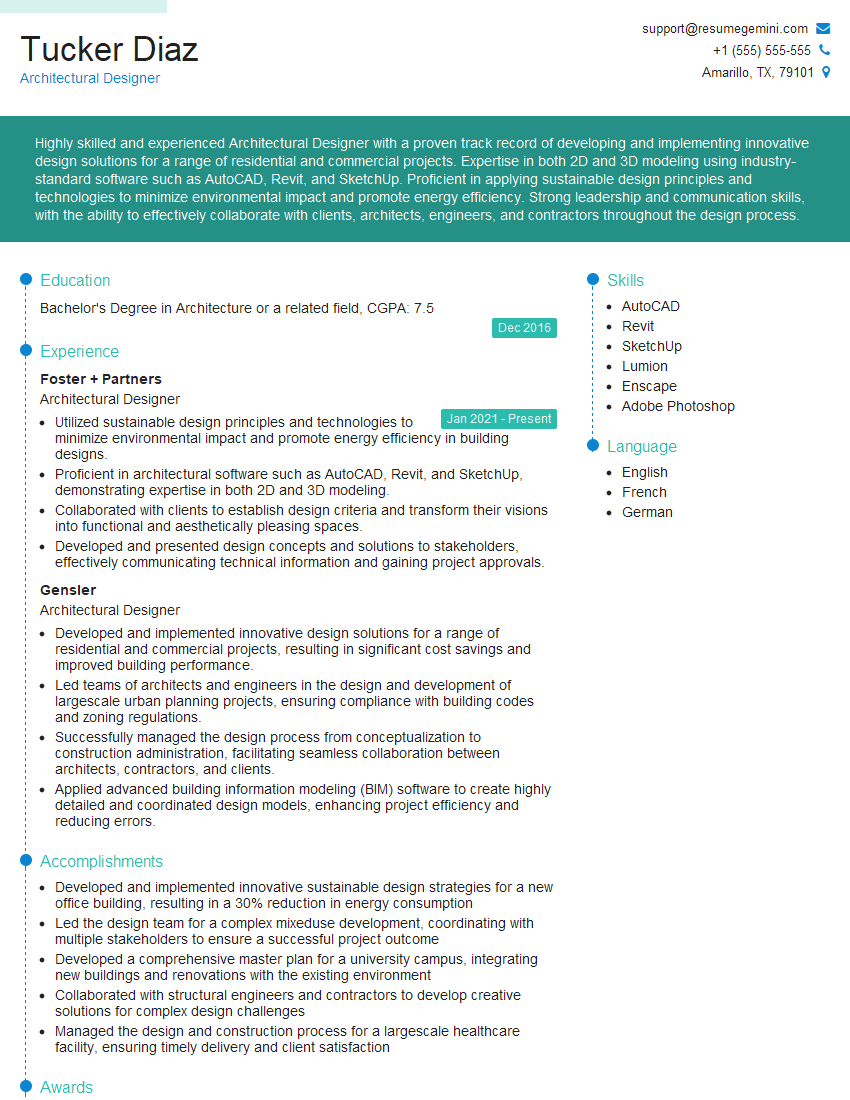
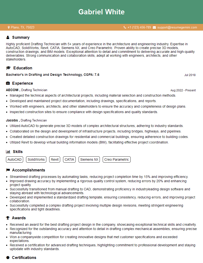
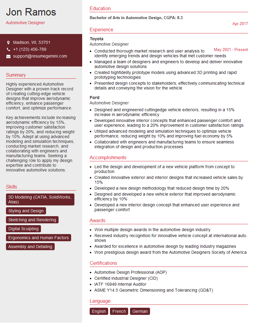
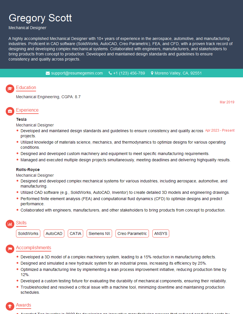
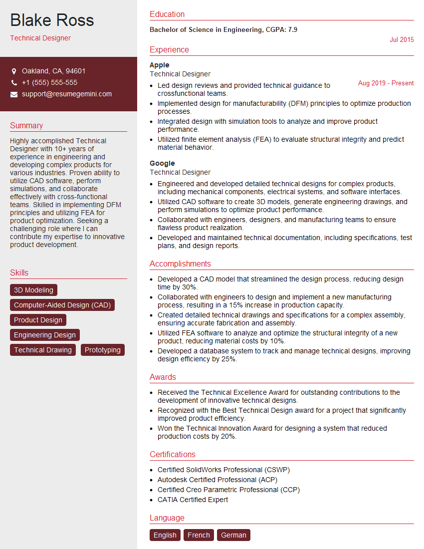
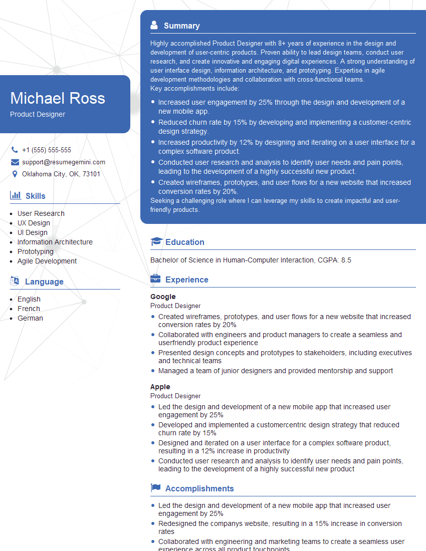
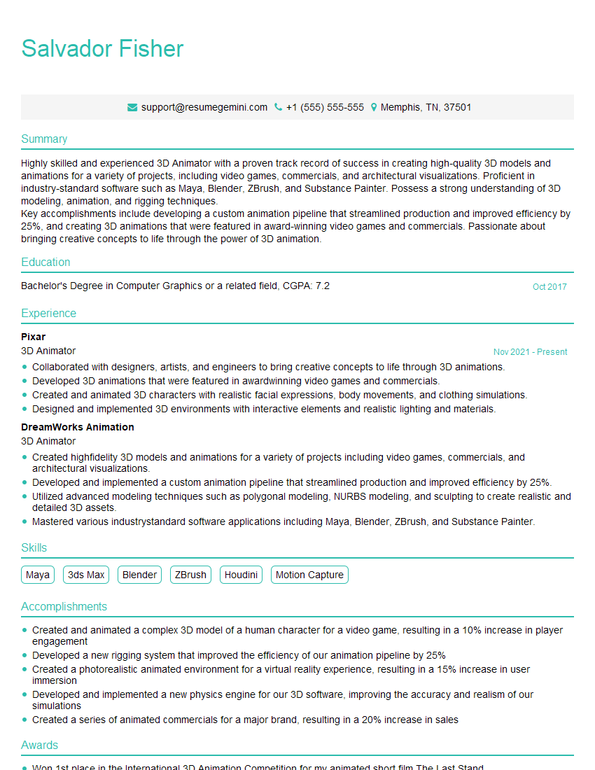
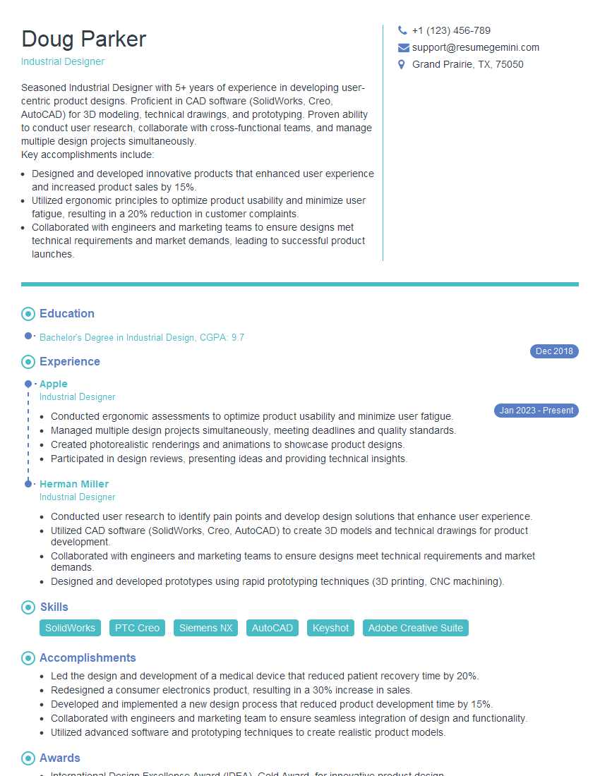
Mastering 3D modeling with SolidWorks and AutoCAD Inventor is crucial for a successful career in engineering, product design, and manufacturing. These skills are highly sought after, opening doors to exciting opportunities and career advancement. To maximize your chances of landing your dream job, a well-crafted resume is essential. An ATS-friendly resume helps your application stand out and bypass automated screening systems. ResumeGemini is a trusted resource for building professional, impactful resumes. We provide examples of resumes tailored to 3D Modeling (SolidWorks, AutoCAD Inventor) roles to guide you in creating your best application.
Explore more articles
Users Rating of Our Blogs
Share Your Experience
We value your feedback! Please rate our content and share your thoughts (optional).
What Readers Say About Our Blog
Hello,
We found issues with your domain’s email setup that may be sending your messages to spam or blocking them completely. InboxShield Mini shows you how to fix it in minutes — no tech skills required.
Scan your domain now for details: https://inboxshield-mini.com/
— Adam @ InboxShield Mini
Reply STOP to unsubscribe
Hi, are you owner of interviewgemini.com? What if I told you I could help you find extra time in your schedule, reconnect with leads you didn’t even realize you missed, and bring in more “I want to work with you” conversations, without increasing your ad spend or hiring a full-time employee?
All with a flexible, budget-friendly service that could easily pay for itself. Sounds good?
Would it be nice to jump on a quick 10-minute call so I can show you exactly how we make this work?
Best,
Hapei
Marketing Director
Hey, I know you’re the owner of interviewgemini.com. I’ll be quick.
Fundraising for your business is tough and time-consuming. We make it easier by guaranteeing two private investor meetings each month, for six months. No demos, no pitch events – just direct introductions to active investors matched to your startup.
If youR17;re raising, this could help you build real momentum. Want me to send more info?
Hi, I represent an SEO company that specialises in getting you AI citations and higher rankings on Google. I’d like to offer you a 100% free SEO audit for your website. Would you be interested?
Hi, I represent an SEO company that specialises in getting you AI citations and higher rankings on Google. I’d like to offer you a 100% free SEO audit for your website. Would you be interested?
good


