Interviews are more than just a Q&A session—they’re a chance to prove your worth. This blog dives into essential Blueprinting and Technical Drawings Interpretation interview questions and expert tips to help you align your answers with what hiring managers are looking for. Start preparing to shine!
Questions Asked in Blueprinting and Technical Drawings Interpretation Interview
Q 1. Explain the difference between orthographic and isometric projections.
Orthographic and isometric projections are two different ways of representing a three-dimensional object in a two-dimensional drawing. Think of it like taking photos of a building from different angles. Orthographic projection uses multiple views (typically front, top, and side) to show the object’s dimensions accurately. Each view shows only two dimensions, displaying the object ‘straight on’. Isometric projection, on the other hand, shows a single view with all three dimensions visible at once, albeit slightly distorted. It’s like taking a slightly skewed photo that still gives a sense of depth.
Orthographic Projection: Imagine a box. An orthographic projection would show you separate drawings: one showing the front face (width and height), one showing the top face (length and width), and one showing the side face (height and length). Each view is a true representation of the object’s dimensions along those planes.
Isometric Projection: In contrast, an isometric projection would give you a single, angled view where you can see the front, top, and side simultaneously. While it provides a good visual representation of the object’s shape, the dimensions are not true to scale and require calculations to obtain accurate measurements.
In practice, orthographic projections are used when precise dimensions are crucial, like in construction blueprints. Isometric projections are useful for quickly visualizing the object and understanding its general shape and spatial relationships.
Q 2. How do you interpret different line types and weights on a blueprint?
Line types and weights on a blueprint are crucial for conveying information about the different elements of a design. Think of them as a visual code. Different line types represent different parts of the construction; for example, thick lines might represent walls and thin lines might represent outlines. Weight communicates the importance or function of an element. Here’s a breakdown:
- Thick, solid lines: Usually represent visible edges or outlines of primary components like walls, columns, and major structural elements.
- Thin, solid lines: Represent centerlines, hidden lines, and less significant elements like doors and smaller details.
- Dashed lines: Indicate hidden features or outlines not immediately visible in the selected view, such as plumbing within a wall.
- Dotted lines: Often represent construction elements or sections that are proposed or might need further details in another drawing.
- Long-and-short dash lines: Frequently designate elements that are part of the adjacent section and need to be connected.
Line Weights: Thicker lines often denote more significant elements; thinner lines indicate smaller or less critical parts. This visual hierarchy helps in quickly understanding the drawing’s structure and priorities. For instance, a thicker wall line might imply a load-bearing wall whereas a thinner line suggests a partition wall.
Ignoring these conventions can lead to misinterpretations and potentially costly errors during construction.
Q 3. What are the standard symbols for doors, windows, and plumbing fixtures?
Standard symbols for architectural and plumbing elements vary slightly depending on the specific drafting standards followed (e.g., ANSI, ISO). However, common conventions exist that allow for easy identification. Remember that the specific representation might be different in other places and you should always follow project-specific symbology guides.
- Doors: Doors are typically represented by a simple rectangular symbol, with swinging doors often having an arc indicating the swing direction. Specific door types (sliding, folding) might have additional symbols or labels.
- Windows: Often shown as a rectangular or square symbol, with possible additional lines or shading to denote window panes or special features like casements or bay windows.
- Plumbing Fixtures: Standard symbols for plumbing fixtures include: a circle for a sink, a simplified outline for a toilet, and a stylized shape for a shower.
The best approach is to always consult the blueprint’s legend or key, which usually clarifies the meaning of each symbol. This legend is crucial for consistent interpretation.
Q 4. Describe your experience with various CAD software packages (e.g., AutoCAD, Revit).
I have extensive experience with various CAD software packages, including AutoCAD and Revit. My experience with AutoCAD spans over a decade, where I’ve leveraged its 2D drafting capabilities for creating detailed drawings, plans, sections, and elevations for various projects, from residential buildings to commercial spaces. I’m proficient in creating and editing drawings, managing layers, generating schedules, and performing quantity take-offs.
My proficiency with Revit, a BIM (Building Information Modeling) software, extends to developing 3D models, creating detailed construction documents, and coordinating various building systems (MEP, structural). I use Revit to generate accurate and comprehensive construction documents, including schedules, quantity take-offs, and clash detection reports, streamlining the construction process and improving collaboration among different disciplines.
I am also familiar with other drafting and design tools which helps me easily integrate with different project needs. I understand how to manage and utilize the capabilities of all programs to successfully create and communicate information effectively.
Q 5. How do you identify and resolve inconsistencies or errors in blueprints?
Identifying and resolving inconsistencies in blueprints requires a systematic approach. It’s like being a detective, looking for clues that don’t match up. My process involves:
- Cross-referencing: I meticulously compare different drawings (floor plans, sections, elevations, details) to check for discrepancies. For example, verifying that door locations and dimensions are consistent across all views.
- Dimension checks: I verify that dimensions are consistent throughout the plans, ensuring there are no conflicting or missing measurements. I’ll carefully check for any additive or subtractive errors.
- Symbol review: I check for discrepancies or ambiguities in the use of symbols. The legend is key to ensuring symbols are appropriately utilized.
- Coordinate verification: Especially in large projects, I verify that the coordinate systems are consistent across all drawings, ensuring that different sections seamlessly connect.
- Clash detection (using BIM software): In Revit, I can utilize clash detection tools to identify conflicts between different building systems (e.g., plumbing running through a structural beam), which is a common source of inconsistencies.
Once inconsistencies are identified, resolving them involves collaboration with the design team to determine the correct information and update the drawings accordingly. Documentation of the changes is essential for future reference.
Q 6. Explain your process for understanding and interpreting construction details.
Understanding and interpreting construction details requires a thorough and methodical approach. Construction details are like zoomed-in instructions for specific parts of the building, showing intricate joinery, connections, and material specifications. My process is:
- Identify the scope: I start by clearly understanding the specific construction element being detailed (e.g., a window connection, a roof detail).
- Analyze the drawing: I carefully examine each line, symbol, and note. I look for indications of materials, dimensions, and the sequence of construction steps. Understanding the scales and their relative sizes is paramount.
- Identify materials and finishes: Pay close attention to materials specified (concrete, wood, steel), their dimensions and specifications and any finishing requirements (painting, sealant).
- Understand construction sequence: Details often implicitly or explicitly show the order of construction steps. This is crucial for proper installation and avoiding conflicts.
- Cross-reference with other drawings: I cross-check the detail with relevant floor plans, sections, or elevations to ensure it’s accurately placed and integrated within the overall design.
Experience is key to interpreting construction details effectively. Knowing typical construction practices and common detailing techniques significantly accelerates comprehension and reduces potential misunderstandings.
Q 7. How familiar are you with building codes and regulations related to blueprints?
I’m very familiar with building codes and regulations, understanding their crucial role in ensuring the safety and functionality of buildings. My understanding encompasses various codes, including IBC (International Building Code), ADA (Americans with Disabilities Act) requirements, and local building ordinances.
During blueprint review, I check the drawings against these standards to verify compliance with the code requirements concerning structural stability, fire safety, accessibility, and energy efficiency. For instance, I’d verify that egress pathways meet code requirements, ensuring adequate space for escape routes, and that the design conforms to accessibility provisions for individuals with disabilities. This compliance review helps prevent costly errors and ensures the project meets legal and safety standards.
I recognize that codes can vary based on location and project type; therefore, I always verify the relevant codes applicable to the specific project I’m working on and I consult with authorities when any uncertainty arises. Staying updated on code changes is also an essential part of my professional practice.
Q 8. Describe your experience working with large-scale blueprints and project plans.
My experience with large-scale blueprints and project plans spans over a decade, encompassing diverse projects from industrial facilities to high-rise buildings. I’ve worked extensively with sets containing hundreds of sheets, often coordinated across multiple disciplines – architectural, structural, MEP (Mechanical, Electrical, Plumbing), and fire protection. I’m proficient in navigating complex numbering systems, understanding sheet cross-referencing, and coordinating information across various drawings. For instance, on a recent project involving a large manufacturing plant, I was responsible for integrating the process flow diagrams with the detailed equipment layouts to identify potential spatial conflicts and optimize the facility’s overall efficiency. This required not only interpreting individual blueprints but also understanding the overall project goals and the interrelationships between different systems.
Q 9. How do you manage revisions and updates to blueprints?
Managing revisions and updates to blueprints is crucial for maintaining project accuracy and preventing costly errors. We utilize a robust revision control system, typically involving a centralized digital repository (like Autodesk BIM 360 or similar). Each revision is clearly marked with a revision number and date, indicating the changes made. This ensures traceability and allows for easy identification of the current ‘as-built’ documentation. Revisions are often tracked using a log that summarizes the changes, including who made the change and the reason for the alteration. Furthermore, a change order system is typically employed, requiring formal approval for any modifications to the original design. Think of it like version control in software development; it’s essential for managing complex documents collaboratively and avoiding confusion.
Q 10. How would you handle a situation where blueprints are unclear or incomplete?
Dealing with unclear or incomplete blueprints requires a methodical approach. First, I would identify the specific areas of ambiguity or missing information. Then, I would consult the project documents, including specifications, design notes, and meeting minutes. I would also leverage my experience to infer missing details based on standard practices and design conventions. If necessary, I would communicate with the design team or the client to clarify the uncertainties. For example, if a dimension is missing, I might check similar details within the same drawing or related drawings to estimate a reasonable value. However, it is crucial to document any assumptions made and communicate them clearly to relevant stakeholders to prevent future problems. If direct clarification is impossible, I’d propose a ‘request for information’ (RFI) to the design team for official clarification.
Q 11. Explain the importance of dimensioning and tolerancing in blueprints.
Dimensioning and tolerancing are fundamental to blueprint interpretation and construction. Dimensions provide precise measurements, ensuring components fit together accurately. Tolerances define acceptable variations from the specified dimensions. Without precise dimensioning and tolerances, the final product may not function correctly and could lead to costly rework. For example, a tolerance of ±0.5 mm on a critical dimension in a mechanical assembly might mean the difference between a smooth-running machine and one that malfunctions. Understanding the various types of tolerances – unilateral, bilateral, and geometric dimensioning and tolerancing (GD&T) – is essential for accurately interpreting and implementing blueprint specifications.
Q 12. Describe your experience with using section views and detail views in blueprints.
Section views and detail views are critical for visualizing internal structures and clarifying complex features. Section views reveal internal components by ‘cutting’ through the object, while detail views enlarge specific features for greater clarity. I’ve used these extensively, for example, in interpreting HVAC system layouts. A section view would show how ducts are routed through a wall, while a detail view might highlight the specific connections and fittings. My experience with these types of views helps in understanding the overall assembly and in identifying potential problems before construction starts. Effective use of these views allows for detailed understanding of seemingly simple components.
Q 13. How do you determine the scale of a blueprint?
The scale of a blueprint is typically indicated in the drawing’s title block or legend. Common scales include 1:100, 1:50, 1:20, etc. These scales indicate the ratio between the drawing dimensions and the actual dimensions. If the scale is not clearly stated, I can determine it by comparing a known dimension (like a door width) on the drawing to its actual dimension. This is done by carefully measuring the dimension on the drawing and comparing it to the actual measurement mentioned in the specifications or from the site survey. By creating a ratio of the drawn dimension to actual, the scale can be inferred.
Q 14. What are your strategies for efficient blueprint reading and interpretation?
Efficient blueprint reading and interpretation involves a systematic approach. I begin by reviewing the title block to understand the project, date, revision, and scale. Then, I examine the overall layout to get a general understanding of the design. Next, I focus on specific details, utilizing section views and detail views as necessary. I use measuring tools and calculators to verify dimensions and identify potential discrepancies. Familiarization with industry standards and symbology is essential to expedite the process. I often use layers to isolate the information that I’m currently focusing on. Finally, creating concise notes and annotations helps in documenting my interpretations and identifying any issues for discussion with the team.
Q 15. Explain your understanding of material specifications as depicted on blueprints.
Material specifications on blueprints are crucial for ensuring the correct materials are used during construction. They’re typically indicated using a combination of text, symbols, and sometimes reference numbers linked to a separate specification document. For example, you might see something like “Concrete: ASTM C39, 3000 psi” indicating a specific type of concrete meeting a particular strength requirement as defined in the American Society for Testing and Materials (ASTM) standard C39. Other materials, like steel, lumber, and finishes, would have similar detailed specifications, often including grade, size, and any required treatments or coatings. Understanding these specifications is fundamental to ensuring the structural integrity and overall quality of the finished project. Misinterpreting them could lead to costly mistakes and delays.
For instance, specifying the wrong grade of steel for a support beam could compromise the entire structure’s stability. Similarly, using the wrong type of paint for exterior walls could lead to premature deterioration. Therefore, careful review and verification of material specifications is essential.
Career Expert Tips:
- Ace those interviews! Prepare effectively by reviewing the Top 50 Most Common Interview Questions on ResumeGemini.
- Navigate your job search with confidence! Explore a wide range of Career Tips on ResumeGemini. Learn about common challenges and recommendations to overcome them.
- Craft the perfect resume! Master the Art of Resume Writing with ResumeGemini’s guide. Showcase your unique qualifications and achievements effectively.
- Don’t miss out on holiday savings! Build your dream resume with ResumeGemini’s ATS optimized templates.
Q 16. How do you utilize blueprints to coordinate with other trades on a construction site?
Blueprints serve as the central communication hub for all trades on a construction site. They provide a shared visual representation of the project, allowing different trades to understand their individual roles and how their work interrelates with others. For example, the electrical contractor needs to know the location of structural members and plumbing lines to avoid conflicts during wiring installation. Similarly, the plumber needs to understand the location of ductwork for HVAC to prevent clashes.
My approach involves coordinating regular meetings with other tradespeople, using the blueprints to discuss the project phasing, potential conflicts, and collaborative strategies. We often highlight key areas on the blueprints using color-coded annotations and sticky notes to identify potential issues proactively. This collaboration ensures a smooth construction process and minimizes costly rework.
I’ve also found digital collaboration platforms extremely helpful, allowing for real-time annotation and communication on shared blueprint files, improving efficiency and transparency.
Q 17. Describe your experience with different blueprint formats (digital and paper).
I’m proficient with both digital and paper blueprint formats, recognizing the advantages and limitations of each. Paper blueprints offer a tangible, readily accessible format, especially useful in environments with limited digital access. However, they’re susceptible to damage, cumbersome to manage for large projects, and difficult to annotate collaboratively.
Digital blueprints, on the other hand, offer superior flexibility. They allow for easy zooming, layering, and annotation, facilitating collaboration through software like Autodesk BIM 360 or Bluebeam Revu. I’m adept at using these platforms to track revisions, manage markups, and share updated plans with the project team. Regardless of the format, my approach focuses on meticulous review, paying close attention to details, scales, and notations in both formats to ensure a consistent understanding of the project plan.
Q 18. How do you communicate complex technical information clearly based on blueprint analysis?
Communicating complex technical information effectively hinges on clarity and simplicity. When faced with a complex blueprint, my approach involves breaking down the information into smaller, manageable sections. I use plain language, avoiding jargon unless absolutely necessary, and supplementing verbal explanations with visual aids, such as detailed sketches or highlighted sections of the blueprints. I also utilize analogies and real-world comparisons to make the information relatable and easy to understand. For instance, instead of simply saying ‘the beam supports a 20-kip load,’ I might say ‘This beam holds the weight of a small school bus,’ which provides a more concrete understanding of the load.
Another important aspect is active listening and checking for understanding. After explaining a section of the blueprints, I ask clarifying questions to ensure the audience grasped the information. This two-way communication helps to identify any gaps in comprehension and allows me to tailor my explanation accordingly.
Q 19. Describe a time you had to interpret a difficult or ambiguous blueprint.
In one project, we encountered an ambiguous detail on the structural drawings regarding the connection between a steel beam and a concrete column. The drawings lacked sufficient detail on the specified anchoring system. Initial interpretations varied among the structural engineer, the steel fabricator, and the construction crew.
To resolve this, I initiated a collaborative review session involving all parties. We carefully examined the related sections of the plans, cross-referencing them with the specifications and contacting the original design team for clarification. We created detailed sketches to illustrate different possible interpretations and evaluated their feasibility and compliance with building codes. Ultimately, through collaborative analysis and direct communication, we reached a consensus on a safe and compliant connection detail, avoiding potential structural issues and project delays.
Q 20. Explain how you ensure accuracy in your interpretation of blueprints.
Ensuring accuracy in blueprint interpretation requires a multi-faceted approach. First, I always start by verifying the blueprint’s revision number to ensure I’m working with the latest version. I meticulously check the drawing scale and legend to correctly interpret dimensions and symbols. Cross-referencing information across different drawings is also vital, as one drawing may not contain all the necessary information. I use multiple methods to verify my understanding of the plan; including independent calculations, comparing different views of the same element on the plan, and reviewing the general notes and specifications.
Moreover, I conduct thorough quality checks on my interpretations, often including a peer review with another experienced professional, helping to identify potential errors or inconsistencies. In this way, multiple viewpoints can improve accuracy and reduce errors.
Q 21. What are your preferred methods for annotating or marking up blueprints?
My preferred methods for annotating blueprints depend on the format. For paper blueprints, I use highlighters, colored pencils, and sticky notes for highlighting important information, adding comments, and marking potential issues. I always make my annotations legible and clearly indicate the date and my initials. For digital blueprints, I prefer software like Bluebeam Revu or Autodesk BIM 360, which allow for more precise annotations, including measurements, text boxes, and stamps. These digital tools also support version control, allowing for easy tracking of revisions and collaboration with other team members. The key is to maintain a consistent and organized annotation system for efficient communication and record-keeping. Clear, concise, and unambiguous annotations are critical in avoiding misunderstandings.
Q 22. How do you stay updated on changes and advancements in blueprint technology and standards?
Staying current in the rapidly evolving field of blueprint technology and standards requires a multi-pronged approach. I actively participate in professional organizations like the American Institute of Architects (AIA) and attend industry conferences and webinars to learn about the latest software, techniques, and regulatory changes. This ensures I’m abreast of new BIM software features, updated building codes (like IBC), and emerging technologies like laser scanning and 3D printing’s impact on blueprint creation and interpretation.
Furthermore, I subscribe to relevant industry publications and online resources, including professional journals and online forums, to stay informed about best practices and case studies. Regularly reviewing updated standards from organizations like ASTM International (for material specifications) is critical. Finally, I actively seek out opportunities for continuing education and professional development courses focusing on blueprint technology advancements. This continuous learning ensures my skills remain sharp and aligned with industry best practices.
Q 23. How familiar are you with BIM (Building Information Modeling) principles?
I’m highly familiar with BIM (Building Information Modeling) principles and have extensive experience utilizing BIM software in various projects. BIM goes far beyond simply creating digital blueprints; it involves creating and managing a digital representation of the physical and functional characteristics of a place. I understand how to work with various BIM software packages, including Revit, ArchiCAD, and Autodesk Navisworks, to create, modify, and analyze building models. This includes working with different file formats like IFC to ensure interoperability with other stakeholders.
My experience encompasses utilizing BIM for clash detection (identifying conflicts between different building systems), quantity take-offs for accurate material estimations, and generating 4D simulations to visualize construction scheduling. I also understand the importance of BIM for lifecycle management of buildings, allowing for easier maintenance and renovations throughout a structure’s lifespan. Think of BIM as a centralized, intelligent database that everyone on the project can access and update, drastically reducing errors and improving coordination.
Q 24. Describe your experience with using digital collaboration tools related to blueprints.
My experience with digital collaboration tools is extensive. I’ve utilized platforms like Bluebeam Revu, Autodesk BIM 360, and Asite for collaborative markup review, real-time project updates, and efficient document management. For instance, on a recent large-scale commercial project, we used Autodesk BIM 360 to centralize all blueprints, shop drawings, and related documents. This enabled the entire team—architects, engineers, contractors, and subcontractors—to access the latest revisions simultaneously, fostering transparent and efficient communication.
These platforms allow for efficient markup and comment features, reducing the time spent on revisions and minimizing miscommunications. I’m proficient in using these tools to track changes, manage versions, and ensure everyone is working with the most current information. This streamlined workflow not only saves time and resources but also reduces the risk of errors and conflicts.
Q 25. How do you identify potential safety hazards from analyzing blueprints?
Identifying potential safety hazards from blueprints requires a meticulous and systematic approach. I look for potential issues related to structural integrity, electrical hazards, fire safety, and fall protection. For example, I check for proper placement of structural supports, ensuring adequate load-bearing capacity, and verifying the structural calculations. I carefully examine electrical drawings for proper grounding, circuit protection, and the absence of potential short circuits.
Fire safety considerations include evaluating the placement and type of fire suppression systems, and ensuring compliance with fire codes regarding egress paths and material flammability. I also pay close attention to potential fall hazards, checking for guardrail requirements on elevated platforms and proper scaffolding specifications. I’m trained to recognize potential conflicts between various disciplines (e.g., MEP systems interfering with structural elements) that could pose a safety risk during construction.
My process involves a detailed checklist and thorough cross-referencing of various blueprint sections to ensure a holistic safety assessment. This proactive approach to hazard identification helps prevent accidents and injuries on the construction site.
Q 26. Explain your understanding of architectural, mechanical, and electrical blueprints.
My understanding of architectural, mechanical, and electrical blueprints is comprehensive. Architectural blueprints provide a detailed visual representation of the building’s design, including floor plans, elevations, sections, and details. These show the overall layout, room sizes, window and door placement, and other architectural features. Mechanical blueprints illustrate the HVAC (Heating, Ventilation, and Air Conditioning) systems, plumbing, and piping layouts. These include details on pipe sizes, equipment placement, and ductwork configurations.
Electrical blueprints display the building’s electrical systems, including power distribution, lighting fixtures, and communication cabling. These show circuit breaker panels, wiring diagrams, and the location of electrical outlets and switches. I can effectively interpret the symbology and notations used in each type of blueprint and understand the interdependencies between them. For example, I can identify how the placement of HVAC equipment might impact the layout of electrical conduits or how plumbing pipes might affect structural design.
Q 27. What is your experience with checking blueprints for compliance with relevant specifications?
Checking blueprints for compliance with relevant specifications is a core part of my responsibilities. This process involves a meticulous review against various codes and standards, including building codes (like the International Building Code or IBC), local ordinances, and specific project requirements. I cross-reference the blueprint details with the project specifications, ensuring that all aspects of the design meet the required standards and regulations. This involves checking for proper dimensions, material specifications, fire-rating compliance, accessibility requirements, and other critical aspects of the design.
I utilize a systematic approach, typically creating a checklist to ensure comprehensive review. This checklist helps track compliance across various design aspects and facilitates efficient identification of any discrepancies. For example, I would verify that the structural members meet specified load-bearing requirements as outlined in engineering calculations and that the electrical systems conform to the National Electrical Code (NEC).
Q 28. Describe your process for creating accurate and clear shop drawings from blueprints.
Creating accurate and clear shop drawings from blueprints is a critical step in the construction process. My process begins with a thorough understanding of the architectural, structural, mechanical, and electrical blueprints. I then identify the specific details required for the shop drawings, focusing on aspects relevant to fabrication and installation. This often includes detailed dimensions, material specifications, assembly instructions, and any necessary tolerances.
I utilize CAD software, such as AutoCAD, to create detailed shop drawings, incorporating precise dimensions and annotations. I meticulously review these drawings to ensure clarity, accuracy, and completeness. This involves multiple checks to identify and correct any potential discrepancies between the shop drawings and the original blueprints. Before finalization, I often consult with relevant stakeholders, including fabricators and installers, to address any questions or potential issues. This collaborative approach helps ensure the shop drawings are practical, clear, and readily understood by the construction team, leading to efficient and accurate fabrication and installation.
Key Topics to Learn for Blueprinting and Technical Drawings Interpretation Interview
- Blueprint Fundamentals: Understanding scales, dimensions, annotations, and symbols used in various blueprint types (architectural, mechanical, electrical).
- Orthographic Projections: Interpreting multi-view drawings and visualizing 3D objects from 2D representations. Practice translating 2D drawings into 3D models in your mind.
- Isometric and Axonometric Drawings: Understanding and interpreting 3D representations and their applications in construction and manufacturing.
- Section Views and Details: Analyzing sectional drawings to understand internal components and structures. Practice identifying different types of sections (full, half, detail).
- Material Specifications: Identifying materials used based on symbols, annotations, and material property tables within the blueprints.
- Tolerance and Dimensioning: Understanding the implications of tolerances and how they impact the final product. Practice calculating dimensional tolerances and their impact.
- Practical Application: Relate your theoretical understanding to real-world scenarios. Think about how you would use blueprint interpretation in a specific project or situation.
- Problem-Solving: Practice identifying potential issues or discrepancies in blueprints and developing solutions. Consider how you would approach ambiguous or incomplete drawings.
- Software Proficiency: Highlight your experience with CAD software (AutoCAD, Revit, etc.) and your ability to utilize them for blueprint interpretation and creation.
- Blueprint Reading Standards: Familiarity with industry standards and best practices for interpreting blueprints.
Next Steps
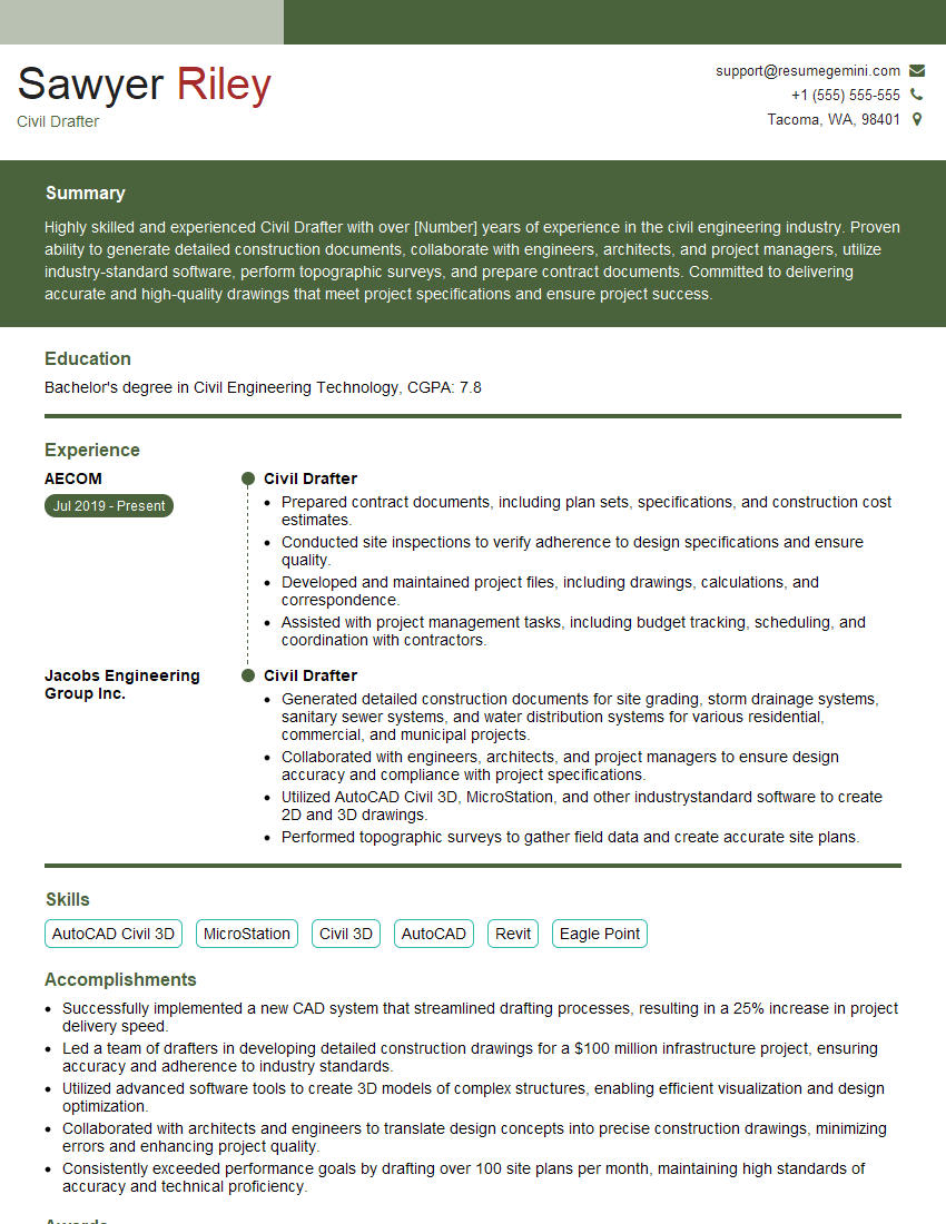
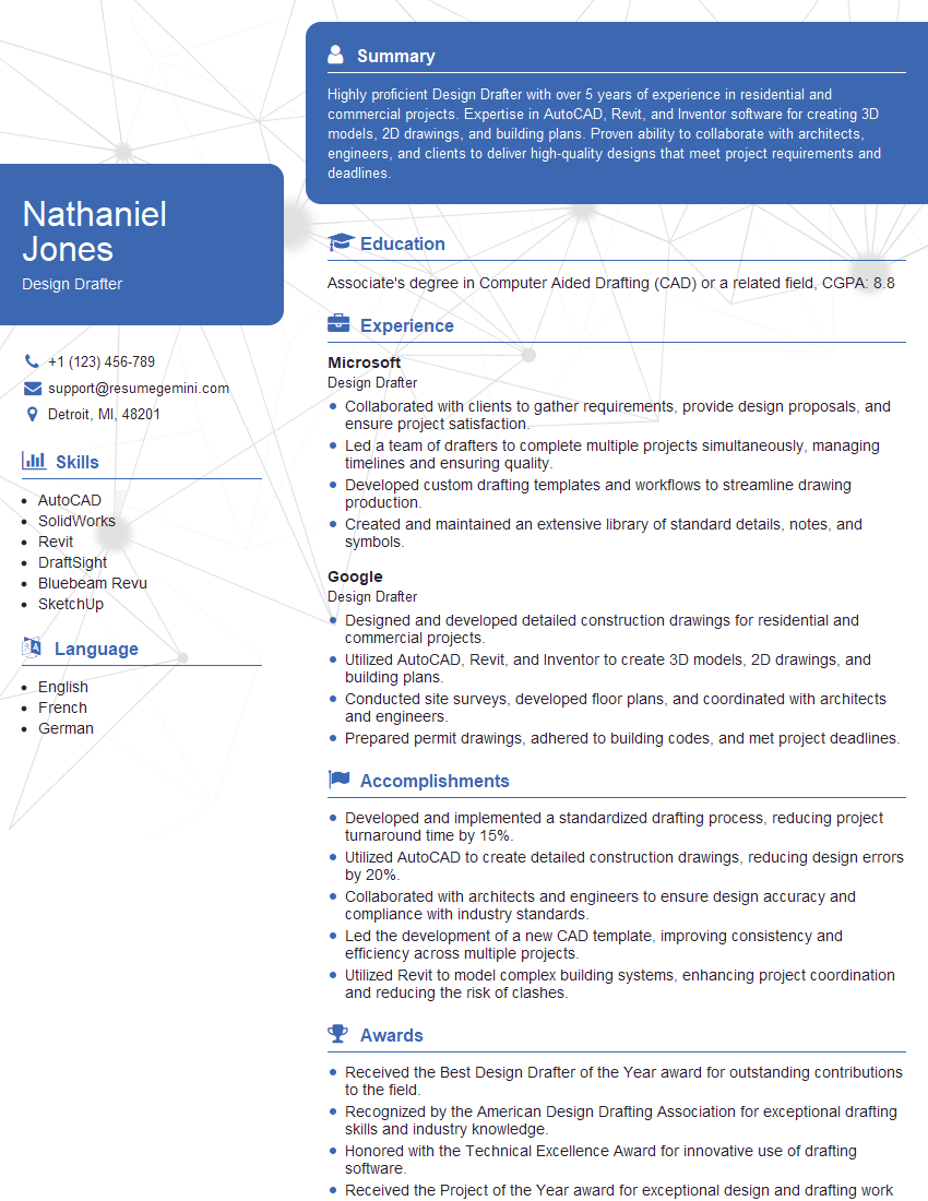
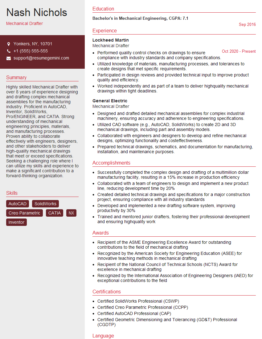
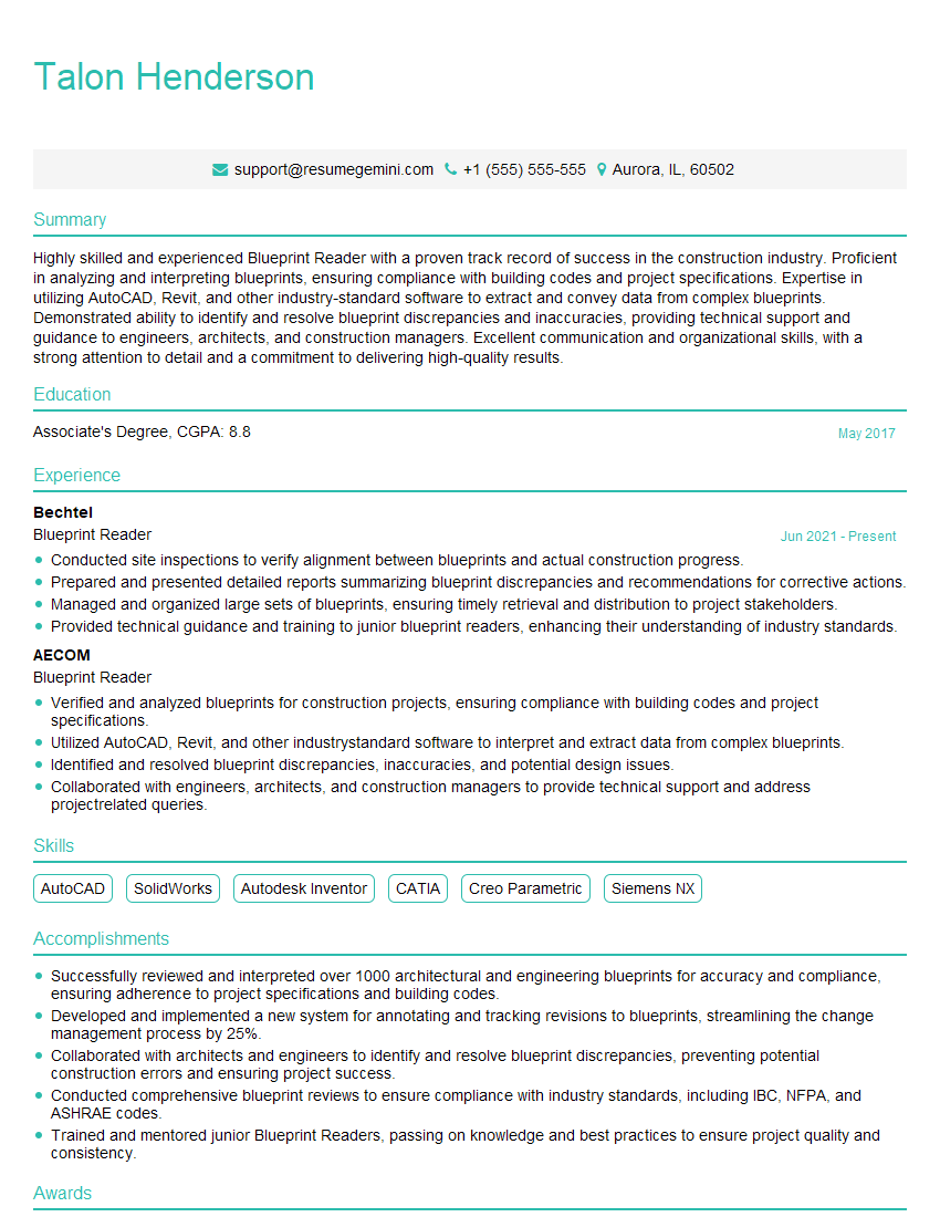
Mastering Blueprinting and Technical Drawings Interpretation is crucial for career advancement in fields like architecture, engineering, construction, and manufacturing. A strong understanding of these skills demonstrates attention to detail, problem-solving abilities, and technical proficiency – highly valued attributes in today’s job market. To increase your chances of landing your dream role, create an ATS-friendly resume that effectively showcases your skills and experience. ResumeGemini is a trusted resource to help you build a professional and impactful resume. They provide examples of resumes tailored to Blueprinting and Technical Drawings Interpretation to help you get started. Invest time in crafting a compelling resume – it’s your first impression on potential employers.
Explore more articles
Users Rating of Our Blogs
Share Your Experience
We value your feedback! Please rate our content and share your thoughts (optional).
What Readers Say About Our Blog
good
