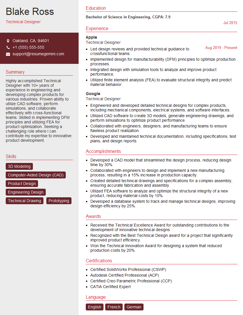
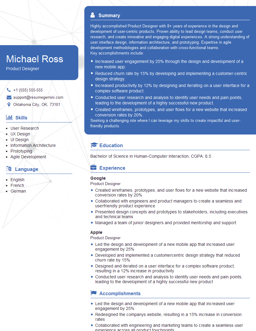
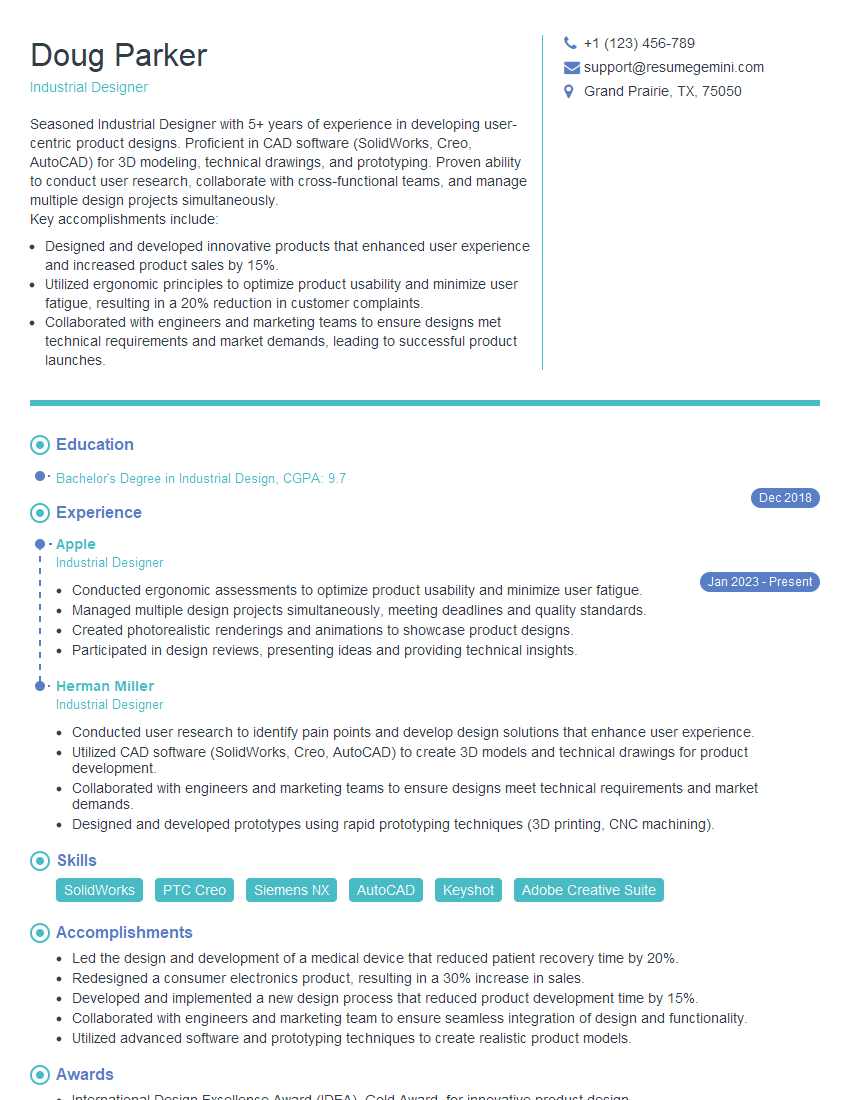
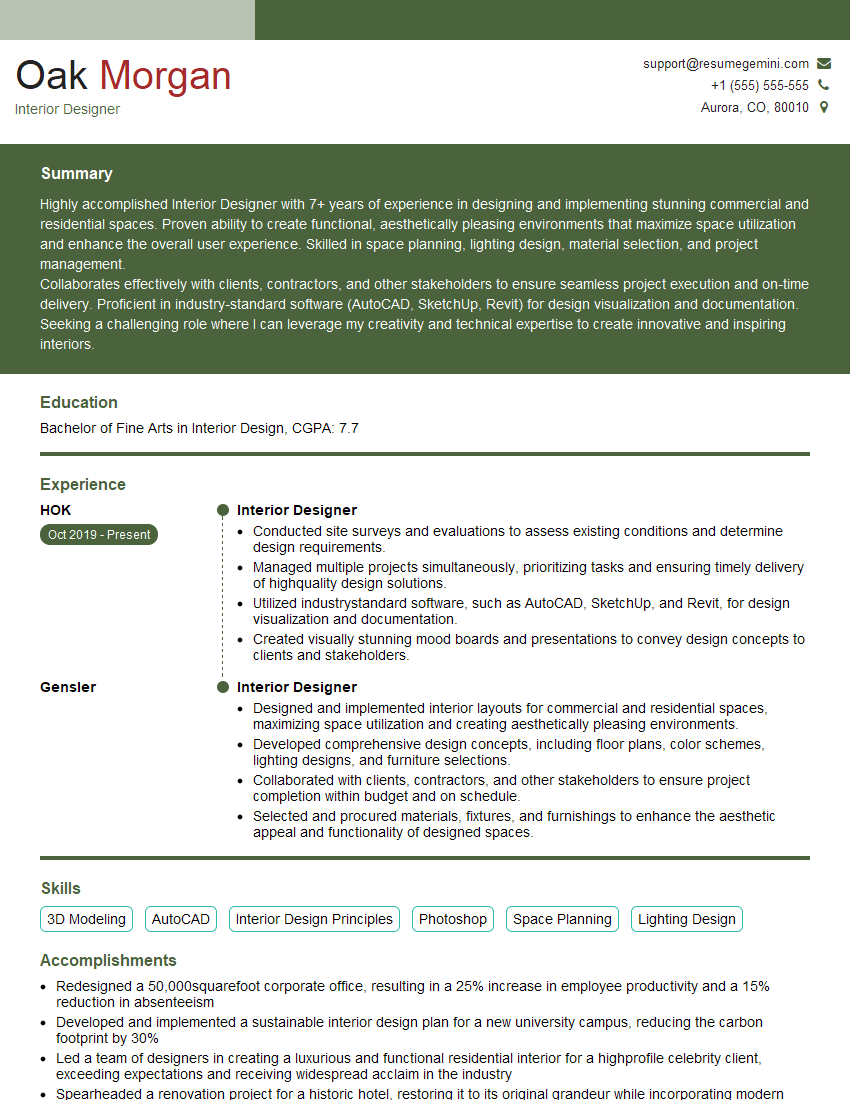
Cracking a skill-specific interview, like one for CAD and Design Software Proficiency, requires understanding the nuances of the role. In this blog, we present the questions you’re most likely to encounter, along with insights into how to answer them effectively. Let’s ensure you’re ready to make a strong impression.
Questions Asked in CAD and Design Software Proficiency Interview
Q 1. Explain your experience with different CAD software packages (AutoCAD, SolidWorks, Revit, etc.).
My experience spans several leading CAD software packages. AutoCAD forms the foundation of my 2D drafting skills; I’m proficient in creating precise drawings, utilizing its powerful command line and extensive libraries of tools for everything from architectural plans to mechanical parts. SolidWorks is my go-to for 3D modeling, particularly for complex mechanical assemblies. I’m experienced in creating and managing parts, assemblies, and drawings within SolidWorks, utilizing features like feature trees, design tables, and simulations. Revit, on the other hand, is my expertise for Building Information Modeling (BIM). I’m comfortable using Revit for creating detailed architectural and structural models, including incorporating MEP (Mechanical, Electrical, and Plumbing) systems. Beyond these three, I have working knowledge of other software such as Fusion 360, which I’ve found particularly useful for its rapid prototyping capabilities. This diverse experience allows me to adapt quickly to different project requirements and client preferences.
- AutoCAD: Proficient in 2D drafting, annotation, and customization.
- SolidWorks: Expert in 3D modeling, assembly design, and simulation.
- Revit: Experienced in BIM, architectural modeling, and structural design.
- Fusion 360: Working knowledge for rapid prototyping and design iteration.
Q 2. Describe your workflow for creating a 3D model from a 2D drawing.
My workflow for creating a 3D model from a 2D drawing involves a systematic approach, prioritizing accuracy and efficiency. First, I thoroughly review the 2D drawing, identifying all critical dimensions, tolerances, and details. Then, I import the 2D drawing into my chosen 3D modeling software (typically SolidWorks). I then use the imported drawing as a guide to create the 3D model, utilizing sketching tools to build up the parts based on the 2D dimensions. Features like extrusion, revolution, and sweep are employed to create the necessary 3D geometry. Throughout this process, I frequently compare the 3D model to the 2D drawing, making adjustments as needed to ensure accuracy. Finally, I perform thorough quality checks, using tools like section views and measurements to verify the model’s dimensions and features match the 2D drawing exactly. Think of it like building a Lego castle from an instruction manual; the manual (2D drawing) provides the blueprint, while the Lego bricks (3D modeling tools) are the means to construct the final product.
Q 3. How do you manage large and complex CAD files?
Managing large and complex CAD files requires a strategic approach, focusing on file organization, data management, and efficient workflows. I employ several techniques. Firstly, I use a structured file naming convention to organize files logically, making them easy to find and retrieve. Secondly, I leverage data management tools, often integrated within the CAD software itself, to manage revisions and versions of the files. Thirdly, I regularly purge unnecessary data from the files to reduce file size and improve performance. Finally, for extremely large projects, I consider employing component-based modeling, where the model is broken down into smaller, more manageable sub-assemblies that can be assembled later. This is similar to assembling a large piece of furniture – each section is built separately and then combined into a whole.
Q 4. What are your preferred methods for creating and modifying drawings?
My preferred methods for creating and modifying drawings are centered around efficiency and precision. For creating drawings, I often leverage parametric modeling techniques which allows for quick modifications when dimensions change. This is especially beneficial in SolidWorks. For modifications, I prefer using the software’s built-in features such as constraints and relationships to ensure that changes are propagated consistently throughout the model. I avoid direct manipulation wherever possible as it can often lead to inconsistencies. For example, changing a single dimension using a parameter automatically updates all dependent dimensions. This prevents common errors and saves significant time.
Q 5. How do you ensure the accuracy and precision of your CAD models?
Ensuring accuracy and precision in CAD models is paramount. I employ a multi-faceted approach. Firstly, I meticulously check all dimensions and tolerances against design specifications. Secondly, I use various verification tools within the CAD software, such as dimensional analysis and interference checks, to identify and rectify any discrepancies. Thirdly, I utilize geometric dimensioning and tolerancing (GD&T) standards to clearly communicate design intent and tolerances, reducing ambiguity. Lastly, in complex projects, I perform regular quality checks and design reviews to catch errors early in the process. This rigorous process helps to prevent costly mistakes later in the design cycle or during manufacturing.
Q 6. Describe your experience with CAD standards and best practices.
I’m well-versed in various CAD standards and best practices. I understand and apply industry standards like ISO, ANSI, and ASME, tailoring my approach based on project requirements. This involves using standardized units, layer management systems, consistent annotation styles, and appropriate file formats for easy collaboration and data exchange. I always aim for clear, well-organized drawings with detailed annotations, ensuring that the design intent is clearly communicated to all stakeholders. My approach includes using design templates and style guides to maintain consistency and efficiency across multiple projects. I also prioritize creating well-documented models and drawings to facilitate ease of use and understanding for others, even if they are not familiar with the specific design.
Q 7. How do you handle conflicting design requirements?
Handling conflicting design requirements requires a methodical and communicative approach. My first step involves clearly identifying and documenting all conflicting requirements. Then, I prioritize the requirements, understanding their relative importance and impact. This often requires collaboration with stakeholders to gain a common understanding and prioritize competing needs, perhaps by using a weighted decision matrix to quantify the relative value of different requirements. Following prioritization, I explore different design solutions that address the most critical requirements. Through iterations and testing, I aim to find a compromise that balances different needs, documenting the trade-offs made along the way. Open communication and clear documentation are crucial throughout this process to ensure transparency and buy-in from all parties.
Q 8. Explain your experience with CAD data management and version control.
Effective CAD data management and version control are crucial for collaborative projects and preventing design conflicts. My experience encompasses utilizing various platforms, including enterprise-level Product Data Management (PDM) systems like Autodesk Vault and Teamcenter, as well as cloud-based solutions like SharePoint integrated with CAD software. These systems allow multiple users to access and modify CAD files concurrently while maintaining a clear history of revisions.
For example, in a recent project designing a complex robotic arm, our team used Autodesk Vault. Each team member checked out specific components, made their modifications, and checked them back in, with Vault automatically creating version numbers and tracking changes. This prevented overwriting each other’s work and allowed us to easily revert to previous versions if needed. We also utilized Vault’s workflow features to manage approvals and ensure design reviews were properly documented.
Beyond PDM systems, I’m proficient in using version control systems like Git, particularly with CAD data that’s been exported to a neutral file format (like STEP or IGES). This allows for tracking changes to design data even outside the native CAD environment, which is especially useful when working with external collaborators or integrating CAD with other software.
Q 9. How familiar are you with parametric modeling techniques?
Parametric modeling is fundamental to my CAD workflow. It’s a powerful technique where design elements are defined by parameters (variables like length, width, diameter, etc.) rather than fixed dimensions. Changes to these parameters automatically update the entire model, ensuring consistency and saving considerable time. This is particularly beneficial in iterative design processes.
Imagine designing a family of engine blocks with varying cylinder counts. Instead of creating separate models for each configuration, a parametric model allows you to adjust a single parameter (number of cylinders) which then automatically adjusts the bore spacing, block dimensions, and other related features. This dramatically accelerates the design process and reduces the chances of errors.
I’m experienced with parametric modeling in various software packages, including SolidWorks, Inventor, and Fusion 360. I understand the importance of establishing robust parametric relationships to ensure the model’s integrity and its responsiveness to design changes. I’m adept at creating families of parts and assemblies using this approach, which is crucial for managing part variations efficiently.
Q 10. How do you troubleshoot errors and problems in your CAD models?
Troubleshooting CAD model errors is a regular part of my work. My approach is systematic and involves several key steps. First, I identify the type of error: is it a geometric error (e.g., overlapping surfaces), a topological error (e.g., gaps in the model), or a performance issue (e.g., slow rendering)?
Once identified, I employ a combination of techniques to resolve the problem. This might involve:
- Visual inspection: Carefully examining the model in various views to pinpoint the problem area.
- Software diagnostics: Using built-in diagnostics tools to pinpoint specific errors flagged by the software.
- Model simplification: Breaking down the complex model into smaller components to isolate the faulty part.
- History review: Checking the model’s design history to identify the point at which the error was introduced.
- External referencing: If the error involves imported data, checking the source data for inconsistencies.
For example, if I encounter an error related to a missing surface, I would use the software’s feature tree to trace back the modeling process and identify the missing or incorrectly defined feature. I might then re-create the feature, ensuring correct constraints and parameters. For performance issues, I often simplify or refine the geometry to reduce the model’s complexity.
Q 11. Describe your experience with rendering and visualization techniques.
Rendering and visualization are critical for communicating designs effectively. My experience includes using various rendering techniques, ranging from simple shaded views to photorealistic renderings. I’m proficient in software like Keyshot, V-Ray, and the rendering capabilities built into CAD packages like SolidWorks and Inventor.
For instance, in a recent project involving a new consumer product, we used Keyshot to create photorealistic renderings that were incorporated into marketing materials. This allowed potential customers to easily visualize the product’s design and features. The ability to adjust lighting, materials, and camera angles was essential for creating compelling visuals. We also employed animations to showcase the product’s functionality, enhancing the communication of design intent.
Beyond photorealistic rendering, I understand the importance of using appropriate visualization techniques for different purposes. For example, simplified wireframe representations are useful for communicating complex assembly relationships quickly, while shaded views are suitable for initial design reviews. Selecting the right rendering technique ensures the design is presented effectively to the target audience.
Q 12. How do you ensure your designs meet the required specifications and standards?
Ensuring designs meet specifications and standards is paramount. My approach is multi-faceted and involves a rigorous verification process throughout the design cycle. This begins with a thorough understanding of the project requirements, which are translated into clear design constraints and targets.
During the design process, I leverage built-in CAD tools for design analysis, such as finite element analysis (FEA) for structural integrity, and computational fluid dynamics (CFD) for fluid flow simulations. This enables me to predict the performance of the design and identify potential issues early in the process. I also routinely utilize tolerance analysis to ensure the design accounts for manufacturing variations.
Finally, rigorous quality checks are performed at various stages, often involving detailed drawings and documentation that incorporate standard symbols and annotations. These drawings are then reviewed by peers and/or subjected to formal design reviews according to industry best practices to ensure compliance with applicable standards and regulations.
Q 13. Explain your experience with collaborating on CAD projects.
Collaboration is essential in CAD projects. I have extensive experience working in teams, utilizing various communication and data sharing methods. This includes using shared network drives, cloud-based collaboration platforms, and PDM systems as discussed earlier. Successful collaboration also requires effective communication and a clear understanding of roles and responsibilities within the team.
In one particular project, our team of five designers used a combination of Autodesk Vault and daily stand-up meetings to coordinate our work on a complex medical device. Vault provided a centralized repository for all design files and revision control, while daily meetings helped identify and resolve potential conflicts or issues promptly. Clear communication ensured everyone understood the design goals and individual responsibilities, allowing for efficient collaboration.
My experience also includes mentoring junior designers, providing guidance and support, and fostering a collaborative team environment where knowledge is shared and best practices are consistently applied.
Q 14. How familiar are you with BIM (Building Information Modeling)?
Building Information Modeling (BIM) is a process involving the generation and management of digital representations of physical and functional characteristics of places. While my primary expertise lies in mechanical design, I have a working understanding of BIM principles and their application in architectural and construction projects. I’ve worked alongside architectural teams and understand how CAD models are integrated into BIM workflows.
My familiarity with BIM includes understanding the use of industry-standard file formats (like IFC) for exchanging data between different software packages used in the AEC industry (Architectural, Engineering, and Construction). I understand the importance of coordinate systems, levels, and other structural information within a BIM context and how these data elements connect to other disciplines involved in a building project.
While I haven’t directly managed BIM projects, I can readily adapt my CAD skills to contribute effectively to a BIM-focused team, ensuring seamless integration of mechanical, electrical, and plumbing (MEP) elements into the overall building model.
Q 15. Describe your experience with CAM (Computer-Aided Manufacturing).
My experience with CAM (Computer-Aided Manufacturing) spans several years and encompasses a wide range of applications. CAM software takes the designs created in CAD and translates them into instructions for manufacturing equipment. I’m proficient in using CAM software to generate toolpaths for various manufacturing processes, including CNC machining (milling and turning), 3D printing, and laser cutting. This involves selecting appropriate cutting tools, optimizing cutting parameters (feed rates, depth of cut, spindle speed) to ensure efficient and precise part production, and managing post-processors to generate machine-specific code.
For instance, in a recent project involving the manufacture of a complex aluminum part, I used Mastercam to generate toolpaths for a 5-axis CNC milling machine. Optimizing the toolpaths reduced machining time by 15% while maintaining high surface finish quality. I’m also experienced in simulating the machining process within the CAM software to identify potential collisions or issues before actual production, minimizing scrap and maximizing efficiency. My understanding extends to various aspects, including fixture design and setup for optimal machining, and post-processing techniques to refine the generated toolpaths. I am familiar with various CAM software such as Mastercam, Fusion 360, and FeatureCAM.
Career Expert Tips:
- Ace those interviews! Prepare effectively by reviewing the Top 50 Most Common Interview Questions on ResumeGemini.
- Navigate your job search with confidence! Explore a wide range of Career Tips on ResumeGemini. Learn about common challenges and recommendations to overcome them.
- Craft the perfect resume! Master the Art of Resume Writing with ResumeGemini’s guide. Showcase your unique qualifications and achievements effectively.
- Don’t miss out on holiday savings! Build your dream resume with ResumeGemini’s ATS optimized templates.
Q 16. What is your experience with different file formats (DXF, DWG, STEP, etc.)?
I have extensive experience working with a variety of CAD file formats, including DXF, DWG, STEP, IGES, and STL. Each format has its strengths and weaknesses, and understanding these nuances is critical for seamless data exchange and interoperability between different CAD systems and manufacturing processes.
- DXF (Drawing Exchange Format): A widely used, relatively simple format, ideal for exchanging 2D drawings between different CAD systems.
- DWG (Drawing): Autodesk’s proprietary format, offering rich data and features, but often requiring specific software for opening and editing.
- STEP (Standard for the Exchange of Product model data): A neutral, industry-standard format for 3D models, suitable for complex geometries and data exchange across different platforms.
- IGES (Initial Graphics Exchange Specification): Another neutral format for 3D models, similar to STEP but potentially less robust for complex designs.
- STL (Stereolithography): A common format for 3D printing, representing the model as a mesh of triangles.
I’ve encountered scenarios where translating a model between formats introduced minor geometrical errors. To mitigate such issues, I always perform rigorous checks and potentially minor cleaning or repair using CAD software after importing a file, ensuring the integrity of the model before proceeding to further processing, such as manufacturing or rendering.
Q 17. How do you optimize CAD models for efficient rendering?
Optimizing CAD models for efficient rendering involves a multi-faceted approach focusing on simplifying geometry, reducing polygon count, and leveraging rendering software capabilities. The goal is to achieve high-quality visuals while minimizing rendering time and system resource consumption.
- Geometry Simplification: Removing unnecessary details, such as highly detailed textures or complex curves in areas not critical for the rendering, significantly reduces the model’s complexity.
- Polygon Reduction: Using decimation techniques to reduce the number of polygons in the model without sacrificing crucial visual aspects. Tools within CAD software or dedicated programs can help automate this process.
- Level of Detail (LOD): Creating multiple versions of the model with varying levels of detail. The rendering engine can switch between these LODs depending on the camera distance, showing simpler versions when far away and more detailed versions up close.
- Material Optimization: Using simpler materials and textures. For instance, replacing photorealistic materials with simpler ones can dramatically improve rendering speed.
- Appropriate Rendering Settings: Selecting optimal settings within the rendering software for the specific requirements. For instance, using ray tracing for high-quality images but opting for faster techniques like rasterization for quick previews.
For example, when rendering a large architectural model, I employed LOD techniques to represent distant buildings with simplified geometry, allowing the rendering engine to focus on the detailed model close to the camera. This strategy significantly reduced rendering time without affecting the visual quality of the final image.
Q 18. What are your methods for creating detailed and accurate drawings?
Creating detailed and accurate drawings requires meticulous attention to detail and a deep understanding of drafting standards and conventions. My process involves several key steps:
- Clear Model Definition: A well-defined and accurate 3D CAD model is fundamental. This requires careful modeling techniques and regular checks for accuracy.
- Appropriate Views and Sections: Selecting the right views (front, top, side, isometric) and sections to convey all necessary information clearly and concisely.
- Dimensioning and Tolerancing: Precisely dimensioning all critical features according to relevant industry standards (e.g., ASME Y14.5). Specifying appropriate tolerances to control the acceptable variation in manufactured parts.
- Annotations and Notes: Adding necessary annotations, notes, and labels to clarify design details, material specifications, or manufacturing instructions.
- Drafting Standards Compliance: Adhering to relevant drafting standards (e.g., ISO, ANSI) for consistency and clarity.
- Regular Checks and Reviews: Thorough review processes to detect and correct errors before finalization.
For example, when creating drawings for a complex mechanical assembly, I used parametric modeling techniques to ensure that any changes made to the 3D model automatically updated the corresponding 2D drawings. This saved significant time and effort and reduced the risk of errors.
Q 19. Explain your experience with creating technical documentation for CAD models.
My experience in creating technical documentation for CAD models involves generating comprehensive and easily understandable documents that convey design intent, manufacturing information, and assembly procedures. This typically involves creating:
- Detailed Drawings: As discussed previously, these are crucial for manufacturing and assembly.
- Parts Lists: Detailed lists specifying all components, their quantities, and relevant material specifications.
- Assembly Instructions: Step-by-step instructions, often including illustrations, for assembling the model.
- Bill of Materials (BOM): A comprehensive list of all components, their part numbers, and costs, often linked to the CAD model.
- Simulation Data: If simulations were conducted (e.g., FEA, CFD), the results and relevant data are included in the documentation.
For instance, I’ve produced extensive technical documentation for a medical device, including detailed drawings, assembly instructions, and a complete BOM. This documentation was crucial for manufacturing, regulatory approval, and maintenance.
Q 20. How do you stay current with the latest CAD software and technologies?
Staying current with the latest CAD software and technologies is crucial in this rapidly evolving field. I actively employ several strategies:
- Industry Publications and Conferences: I regularly read industry publications (both print and online) and attend conferences to learn about new software releases, innovative techniques, and industry best practices.
- Online Courses and Tutorials: I utilize online learning platforms such as Coursera, Udemy, and LinkedIn Learning to access specialized training courses on advanced CAD techniques and new software features.
- Software Updates and Webinars: I ensure that I install all relevant software updates promptly and participate in webinars and online workshops organized by software vendors.
- Networking with Peers: I maintain an active professional network through industry forums and online communities to share knowledge and learn from other professionals’ experiences.
- Hands-on Practice: I consistently apply newly acquired knowledge through personal projects and work assignments, reinforcing my understanding and building expertise.
For example, recently I completed a course on generative design, learning how to leverage algorithms to create optimized designs based on specified constraints. This has already proved beneficial in streamlining design processes for several projects.
Q 21. Describe your experience with 3D printing and its integration with CAD.
My experience with 3D printing and its integration with CAD is extensive. I’m proficient in preparing CAD models for 3D printing, which involves understanding the limitations and capabilities of different 3D printing technologies (FDM, SLA, SLS, etc.).
- Model Preparation: This includes checking for manufacturability issues such as overhangs, thin walls, and unsupported features. Repairing or modifying the model to address these issues is essential for successful printing.
- Slicing Software: I am proficient in using slicing software to generate toolpaths for 3D printers. This process involves selecting appropriate print settings (layer height, infill density, print speed) to optimize print quality and speed.
- Material Selection: Choosing appropriate materials based on the application and desired properties of the final part is critical. Different materials offer varying levels of strength, flexibility, and durability.
- Post-Processing: Once printed, parts often require post-processing, such as support removal, cleaning, and finishing to achieve the desired surface quality.
I recently used 3D printing to create prototypes of a complex mechanical part. By carefully preparing the CAD model and optimizing the print settings, I was able to produce accurate and functional prototypes in a relatively short time. This allowed for early testing and validation of the design before committing to more expensive manufacturing methods.
Q 22. How do you incorporate user feedback into your design process?
Incorporating user feedback is crucial for successful design. I approach this iteratively, using a multi-stage process. Initially, I conduct thorough user research through surveys, interviews, and usability testing to understand their needs and expectations. This informs the initial design concept. Then, after creating prototypes (often digital ones in CAD), I present these to users for feedback. This feedback is carefully documented and analyzed. I then use this feedback to revise the design, creating new iterations. This cycle repeats until the design effectively meets user needs and expectations. For example, while designing a new ergonomic chair, initial user feedback revealed discomfort in the lumbar support region. This feedback led to redesigning the lumbar support curve and padding, resulting in a significantly improved product.
- Surveys: Gathering quantitative data on user preferences.
- Interviews: Understanding the qualitative aspects of user needs.
- Usability testing: Observing user interaction with prototypes to identify pain points.
Q 23. How do you handle revisions and updates to existing CAD models?
Handling revisions and updates to existing CAD models is a common task demanding meticulous attention to detail and version control. I utilize a version control system (like Git, if appropriate for the project) to track changes, allowing me to revert to previous versions if needed. When making revisions, I always create a new version of the model, clearly documenting the changes made. This prevents accidental overwriting of earlier iterations. Within the CAD software itself, I leverage its revision capabilities to track changes over time. Specific tools like layers and design history significantly help manage the complexity of intricate updates. For instance, when updating a component of a complex assembly, I would isolate that part, make the modifications, and then re-assemble, ensuring that the changes integrate seamlessly without affecting other components.
Example: Version 1.0 – Initial Design; Version 1.1 – Added Feature X; Version 1.2 – Fixed Dimensional ErrorQ 24. What is your experience with creating detailed assembly drawings?
Creating detailed assembly drawings is a cornerstone of my CAD expertise. I approach it systematically, ensuring clarity and precision in conveying design information. The process starts with defining the scope of the drawing, identifying all components and their relationships within the assembly. I then create individual component drawings, which may include detailed views, sections, and annotations to clearly communicate geometric tolerances and material specifications. These drawings are then integrated into the overall assembly drawing, using techniques like exploded views to show the hierarchical structure. Bill of materials (BOMs) are generated, linking each part to its specifications. I pay close attention to standardization, following industry best practices and company standards to ensure consistency and readability. For example, in designing a complex robotic arm, each joint and actuator would be separately detailed in component drawings, which then come together to create a clear and comprehensive assembly drawing.
Q 25. How do you approach the design process for complex projects?
Tackling complex projects requires a structured approach. My methodology begins with a comprehensive understanding of the project’s requirements through thorough client discussions and document reviews. This is followed by breaking down the project into smaller, manageable modules or sub-assemblies. This modular approach facilitates parallel work, allowing for team collaboration and efficient task management. Each module is then meticulously designed, modeled, and analyzed independently before integration. Throughout the process, I use rigorous quality checks and simulations to ensure functionality and performance. Regular progress reviews and stakeholder communication are essential to address any emerging challenges. Imagine designing a whole building; we would break it down into systems (electrical, plumbing, HVAC), which are then further divided into individual components, each managed as a separate but integrated project.
Q 26. Explain your understanding of different types of CAD modeling (wireframe, surface, solid).
CAD modeling involves different techniques depending on the design complexity and the information needed.
- Wireframe modeling: This is the most basic form, utilizing lines and curves to represent the edges of a 3D object. It’s useful for early-stage design conceptualization, giving a skeletal representation, but lacks surface and volume data. Think of it as a blueprint’s line drawing.
- Surface modeling: This creates a 3D model using surfaces. It’s perfect for designs with complex curves and aesthetics, like car bodies. It doesn’t inherently include volume information, though it can be inferred.
- Solid modeling: This is the most comprehensive technique, defining a 3D object with both surface and volume data. This allows for accurate mass calculations, stress analysis, and other critical engineering evaluations. It’s the preferred method for most engineering designs due to its thoroughness. Think of a fully rendered 3D model.
Q 27. How do you ensure the sustainability and efficiency of your designs?
Sustainability and efficiency are paramount in my design process. I aim to minimize material waste by optimizing part designs for efficient manufacturing. This may involve employing generative design techniques or exploring alternative materials with lower environmental impact. I also prioritize energy efficiency in designs wherever applicable, considering factors such as heat dissipation and energy consumption. Lifecycle analysis (LCA) is a valuable tool in assessing the environmental impact of the product over its entire lifecycle, from manufacturing to disposal, allowing for informed design choices. For example, in designing packaging, I would focus on using recycled materials and minimizing packaging volume to reduce both material waste and transportation costs.
Q 28. What is your experience with using design review tools and processes?
I have extensive experience using design review tools and processes, both formal and informal. Formal reviews often involve structured meetings with stakeholders, using tools like dedicated PLM (Product Lifecycle Management) systems, which enable version control, change management, and collaborative review of designs. We use mark-up tools within the CAD software itself to highlight areas needing improvement, allowing for real-time feedback and discussion. Informal reviews involve frequent check-ins with team members, ensuring open communication and early detection of potential issues. These processes are vital in catching errors, enhancing the design, and ensuring everyone is aligned on the project goals. For instance, using a PLM system allows all members of the design team to access the latest version of the model and provide comments directly within the system’s interface, making the entire design process more collaborative and efficient.
Key Topics to Learn for CAD and Design Software Proficiency Interview
- Software Fundamentals: Mastering the interface, navigation, and basic functionalities of your chosen CAD software (e.g., AutoCAD, SolidWorks, Revit). Understanding file formats and data exchange is crucial.
- 2D Drafting & Design: Demonstrate proficiency in creating accurate 2D drawings, including dimensioning, annotations, and layering techniques. Be prepared to discuss your experience with various drawing standards.
- 3D Modeling & Design: Showcase your ability to create and manipulate 3D models, including understanding different modeling techniques (e.g., solid modeling, surface modeling). Be ready to discuss your experience with model cleanup and optimization.
- Technical Drawings & Documentation: Explain your understanding of creating detailed technical drawings, including sections, elevations, and assembly drawings. Highlight experience with creating clear and concise documentation.
- Design Principles & Best Practices: Discuss your knowledge of design principles like ergonomics, aesthetics, and manufacturability. Be ready to explain how you apply these principles in your design process.
- Problem-Solving & Troubleshooting: Prepare examples demonstrating your ability to identify and solve design problems using your CAD software. Highlight your experience with debugging models and resolving design conflicts.
- Software-Specific Features: Deepen your knowledge of advanced features within your chosen software. This might include parametric modeling, simulations, rendering, or specific add-ons relevant to your field.
- Collaboration & Teamwork: Discuss your experience working collaboratively on CAD projects, including version control and data sharing techniques. Highlight your communication skills in a team setting.
Next Steps
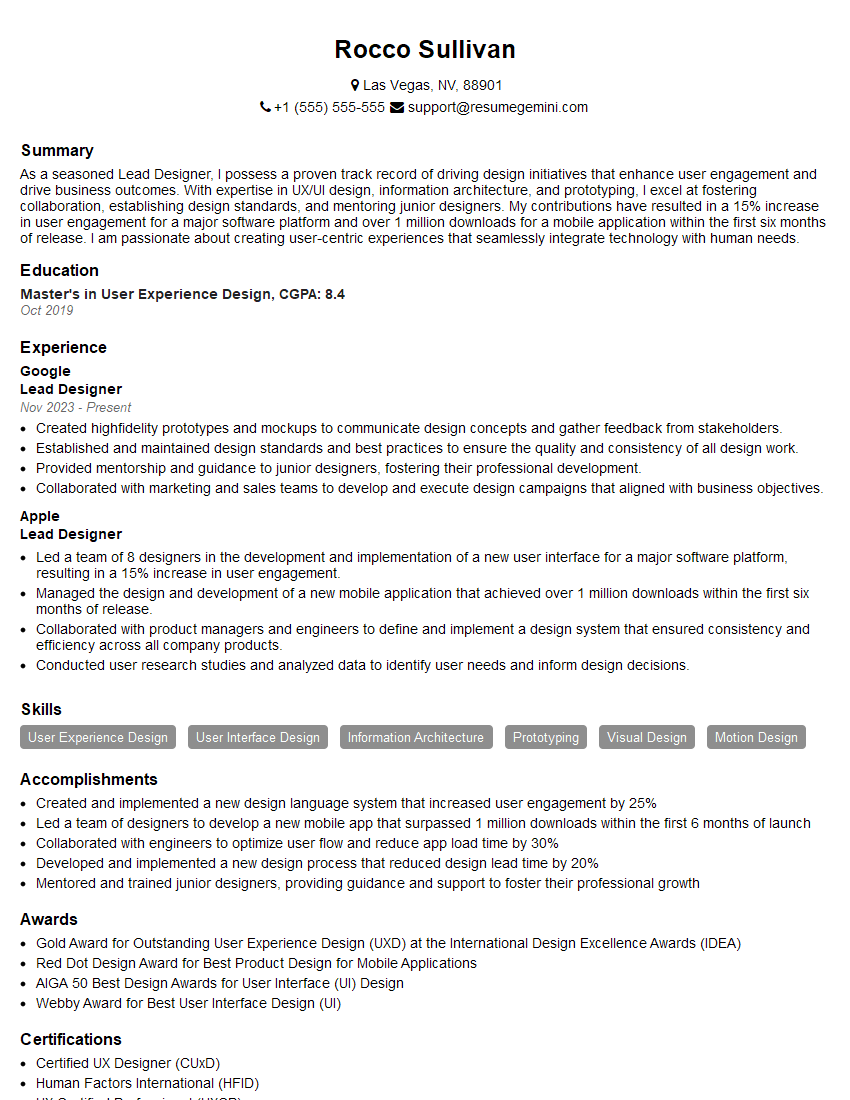
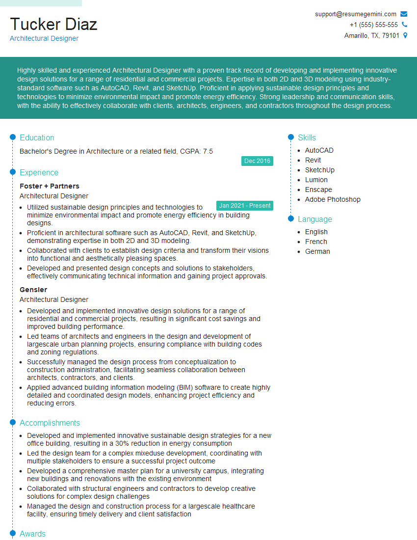
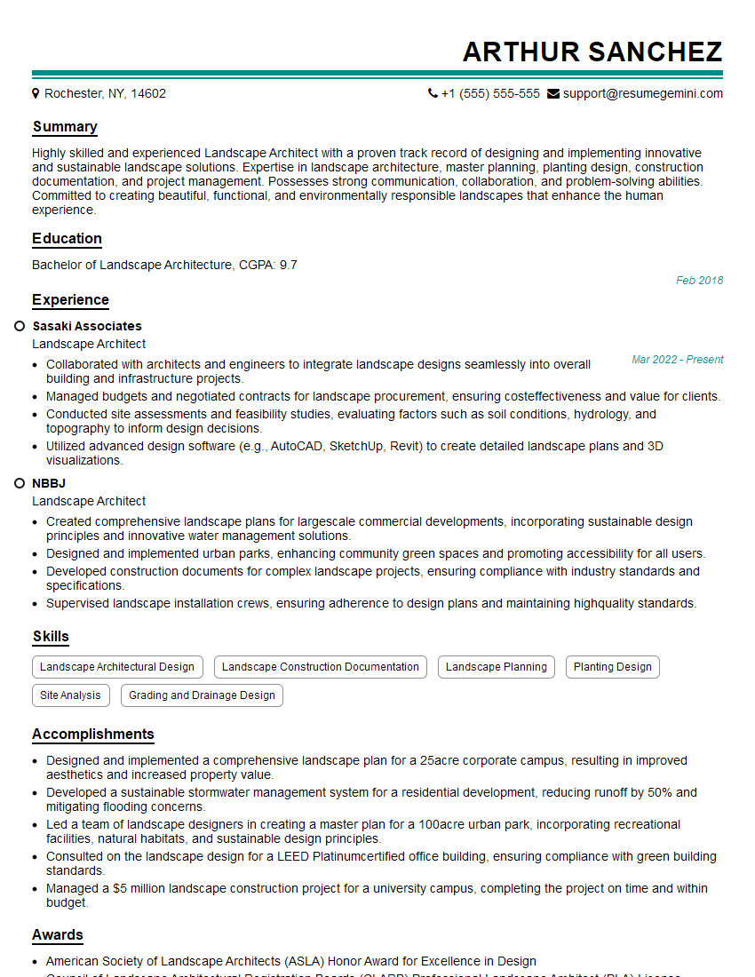
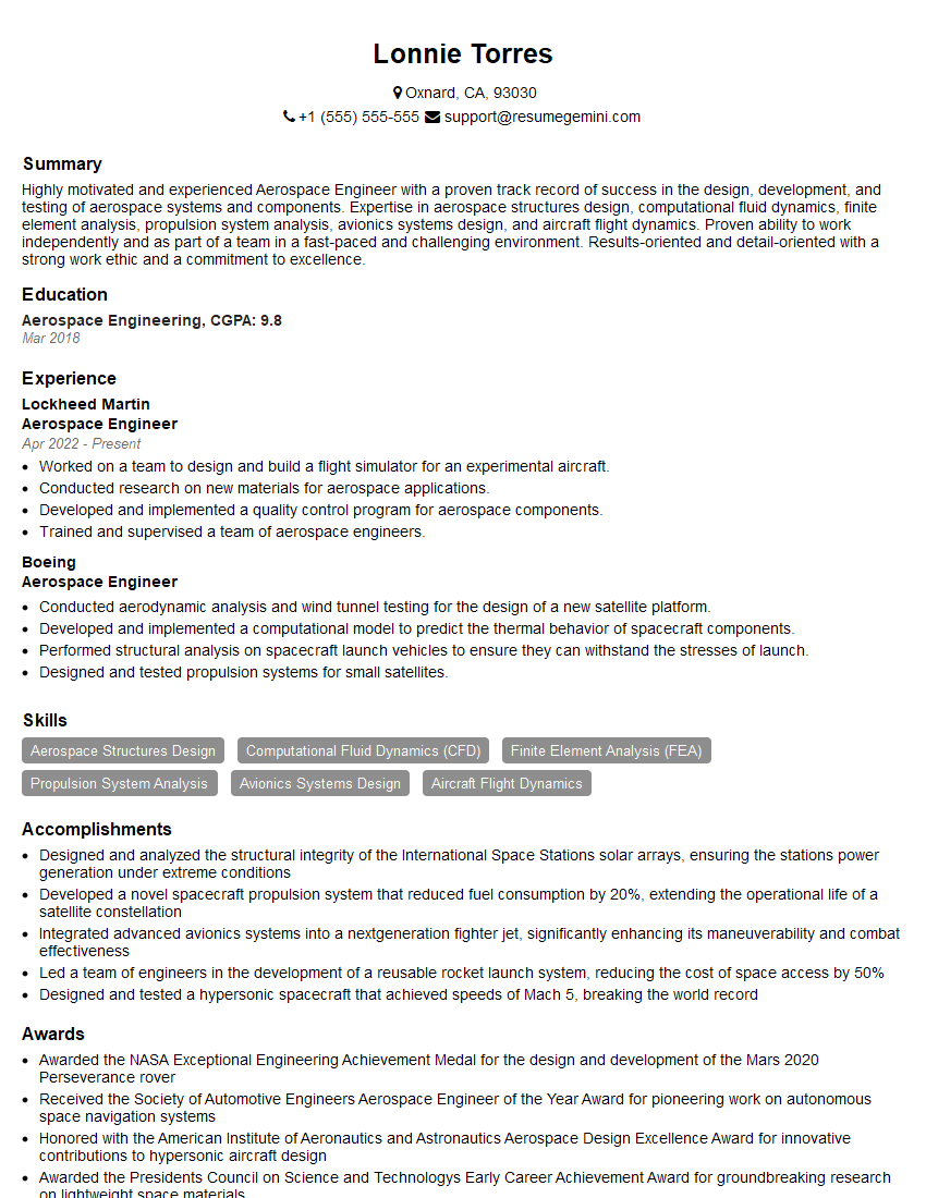
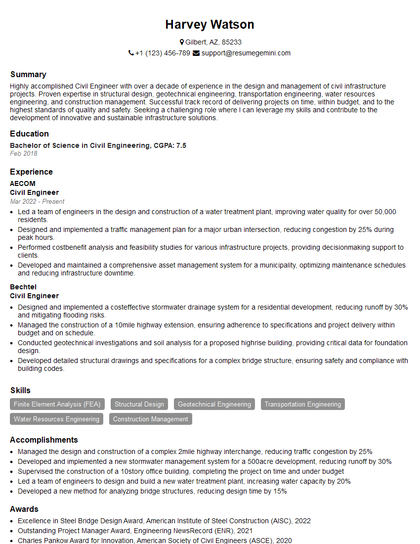
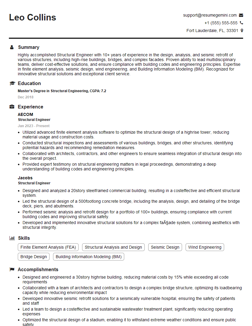
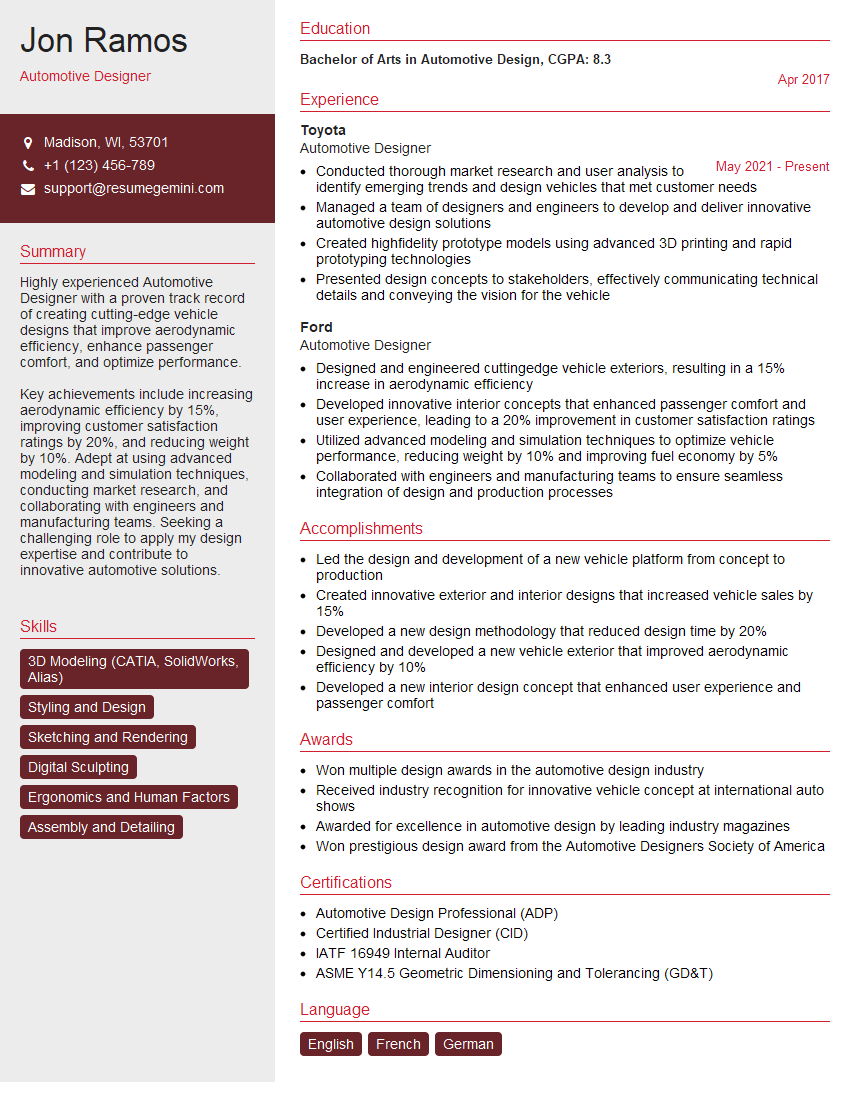
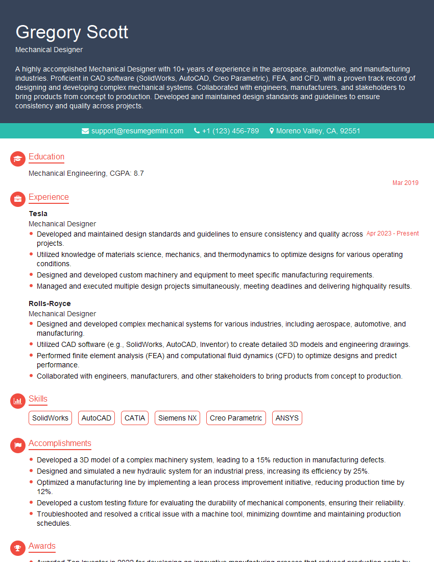
Mastering CAD and Design Software Proficiency is paramount for career advancement in today’s competitive landscape. It opens doors to exciting opportunities and higher earning potential. To maximize your chances of securing your dream role, crafting a compelling and ATS-friendly resume is essential. This ensures your skills and experience are effectively communicated to recruiters and hiring managers. We strongly recommend using ResumeGemini to build a professional and impactful resume tailored to your specific skills and experience. ResumeGemini provides examples of resumes specifically designed for professionals in CAD and Design Software Proficiency, helping you showcase your expertise effectively. Take the next step towards your dream career today!
Explore more articles
Users Rating of Our Blogs
Share Your Experience
We value your feedback! Please rate our content and share your thoughts (optional).
What Readers Say About Our Blog
Hello,
We found issues with your domain’s email setup that may be sending your messages to spam or blocking them completely. InboxShield Mini shows you how to fix it in minutes — no tech skills required.
Scan your domain now for details: https://inboxshield-mini.com/
— Adam @ InboxShield Mini
Reply STOP to unsubscribe
Hi, are you owner of interviewgemini.com? What if I told you I could help you find extra time in your schedule, reconnect with leads you didn’t even realize you missed, and bring in more “I want to work with you” conversations, without increasing your ad spend or hiring a full-time employee?
All with a flexible, budget-friendly service that could easily pay for itself. Sounds good?
Would it be nice to jump on a quick 10-minute call so I can show you exactly how we make this work?
Best,
Hapei
Marketing Director
Hey, I know you’re the owner of interviewgemini.com. I’ll be quick.
Fundraising for your business is tough and time-consuming. We make it easier by guaranteeing two private investor meetings each month, for six months. No demos, no pitch events – just direct introductions to active investors matched to your startup.
If youR17;re raising, this could help you build real momentum. Want me to send more info?
Hi, I represent an SEO company that specialises in getting you AI citations and higher rankings on Google. I’d like to offer you a 100% free SEO audit for your website. Would you be interested?
Hi, I represent an SEO company that specialises in getting you AI citations and higher rankings on Google. I’d like to offer you a 100% free SEO audit for your website. Would you be interested?
good

