Every successful interview starts with knowing what to expect. In this blog, we’ll take you through the top Coaxial Cable Splicing interview questions, breaking them down with expert tips to help you deliver impactful answers. Step into your next interview fully prepared and ready to succeed.
Questions Asked in Coaxial Cable Splicing Interview
Q 1. Explain the process of preparing coaxial cable for splicing.
Preparing coaxial cable for splicing is crucial for a strong, reliable connection. Think of it like preparing the ends of two ropes before tying a knot – you need a clean, even surface for a secure bond. The process involves several steps:
- Cutting the Cable: Use a sharp cable cutter to create a clean, square cut. A jagged cut can damage the inner conductor and cause signal loss.
- Stripping the Outer Jacket: Carefully remove the outer jacket using a cable stripper, being mindful not to nick the braided shield underneath. The length of the jacket removal depends on the connector type being used.
- Stripping the Shield: Gently remove the braided shield, exposing the dielectric insulator. Again, avoid damaging the center conductor. Tools like a specialized coaxial cable stripper are essential for precision.
- Stripping the Dielectric and Inner Conductor: Using the appropriate stripper for the cable type, carefully remove the dielectric insulator, exposing a small length of the center conductor. Be extremely careful not to nick or damage the center conductor.
- Cleaning: Clean the exposed conductor and shield using isopropyl alcohol and a lint-free cloth to remove any debris or oxidation. This ensures optimal contact.
Proper preparation minimizes signal loss and ensures a long-lasting splice.
Q 2. What are the different types of coaxial cable connectors and their applications?
Coaxial connectors come in various types, each designed for specific applications:
- BNC (Bayonet Neill-Concelman): A quick-connect/disconnect type, commonly used in video applications, test equipment, and older Ethernet networks. They’re relatively inexpensive and easy to use.
- F-Type: Very common in cable television and satellite systems, offering a threaded connection for a secure and reliable join. Various versions exist for different cable sizes.
- N-Type: A more robust connector often found in high-frequency applications such as microwave systems and professional broadcast equipment. They handle higher power levels than BNC or F-type connectors.
- SMA (SubMiniature version A): Smaller than N-type, often used in radio frequency (RF) applications, particularly in smaller devices and test equipment.
- TNC (Threaded Neill-Concelman): A threaded version of the BNC connector, providing a more robust connection than its bayonet counterpart.
The choice of connector depends on the frequency, power level, and environment of the application.
Q 3. Describe the steps involved in using a compression connector for coaxial cable.
Using a compression connector involves securing a crimped connector onto the prepared coaxial cable. The process ensures a consistent and reliable connection with minimal signal loss:
- Prepare the Cable: Follow the steps outlined in question 1 to prepare the cable properly.
- Insert the Conductor: Carefully insert the center conductor of the prepared cable into the connector body until it reaches the specified depth. Ensure there are no kinks or damage.
- Secure the Connector: Using a compression tool specifically designed for the chosen connector type, firmly squeeze the connector body onto the cable. This compresses the connector to create a secure, low-impedance connection. Improper compression can result in a poor connection.
- Check the Connection: Inspect the connection to ensure it’s properly crimped and there’s no visible damage.
- Test for Continuity and SWR: Use a time domain reflectometer (TDR) or a cable tester to verify the connection’s continuity and standing wave ratio (SWR) to ensure minimal signal loss and reflections.
Always use the correct compression tool for the specific connector and cable type to ensure a proper connection. Using the incorrect tool can lead to a faulty connection.
Q 4. How do you test the continuity of a coaxial cable after splicing?
Testing the continuity of a coaxial cable after splicing involves checking for any breaks or discontinuities in the signal path. This is typically done using a Time Domain Reflectometer (TDR) or a simple multimeter and continuity tester (for simple checks).
Using a TDR: A TDR sends a signal down the cable and measures the reflections. A clean, continuous signal reflects back without any significant impedance mismatch. Any reflections indicate a problem.
Using a Multimeter: For a basic continuity check, you can use a multimeter set to the continuity setting. Connect the probes to the center conductor and shield at each end of the splice. A continuous tone or reading indicates a good connection. However, a multimeter will not reveal impedance mismatch.
A proper splice will show continuous conductivity and minimal impedance mismatch, ensuring that the signal passes through without significant loss or reflection.
Q 5. What are the common causes of signal loss in coaxial cable, and how can they be addressed?
Signal loss in coaxial cables is a common problem stemming from various factors:
- Poor Connections: Loose or improperly made connections (splices or connectors) are major culprits. This introduces impedance mismatches and reflections.
- Cable Damage: Bending, kinking, crushing, or cuts in the cable disrupt the signal path.
- Water Ingress: Moisture within the cable causes corrosion and significantly increases attenuation (signal loss).
- Environmental Factors: Extreme temperatures and exposure to corrosive chemicals can degrade the cable’s performance.
- Improper Shielding: A compromised shield allows interference to enter and degrade the signal.
Addressing Signal Loss: Solutions involve carefully examining the cable and connections. Reseat connectors, replace damaged sections, ensure proper sealing to prevent water ingress, and replace any damaged shielding. A TDR helps to pinpoint the exact location of the fault.
Q 6. Explain the difference between a crimp connector and a compression connector.
The main difference lies in how the connector is attached to the cable:
- Crimp Connectors: These use a crimping tool to mechanically secure the connector onto the cable. The tool compresses a metal ring around the cable, creating a mechanical bond. They are generally less expensive but require precise crimping for a good connection. An improper crimp can result in intermittent signal problems.
- Compression Connectors: These use a compression tool to squeeze the connector’s body firmly onto the cable. This compresses the cable against the connector’s internal components, creating a low-impedance electrical connection. They often provide a superior and more reliable connection than crimp connectors, especially at higher frequencies. Compression tools are generally more expensive than crimping tools.
The choice depends on the application, budget, and the level of reliability required. For critical applications or higher frequencies, compression connectors are preferred.
Q 7. What safety precautions should be taken while working with coaxial cables?
Safety is paramount when working with coaxial cables, especially those carrying high-frequency signals or high voltages:
- Eye Protection: Always wear safety glasses to protect your eyes from potential debris or sparks.
- Proper Tools: Use the right tools for the job. Improper tools can lead to injury or damage to the cable.
- Grounding: Ground yourself and the equipment to prevent static electricity buildup, which can damage sensitive electronics.
- High Voltage Awareness: Some coaxial cables carry significant voltages. Never work on energized cables without proper training and safety equipment.
- Sharp Tools Caution: Coaxial cable strippers and cutters are sharp. Handle them carefully to avoid cuts.
- Work Area Safety: Maintain a clean and organized workspace to avoid accidents.
Always refer to the manufacturer’s safety guidelines for specific cable types and connectors.
Q 8. How do you identify different types of coaxial cables?
Identifying different coaxial cables involves examining several key characteristics. Think of it like identifying different types of pipes – each has a specific purpose and construction.
- Connector Type: The most obvious difference is the connector at each end (e.g., F-type, BNC, RCA). Different connectors are designed for different applications and frequencies.
- Impedance: This is crucial! Coaxial cables are designed with a specific characteristic impedance, usually 50 ohms or 75 ohms. This is printed on the cable jacket itself or is indicated in the cable specifications. Mismatched impedance leads to signal loss. Think of it like trying to force water through a pipe that’s too narrow – you lose pressure (signal strength).
- Outer Diameter: The outer diameter (OD) of the cable varies depending on its application and frequency. Thicker cables generally handle higher frequencies and power levels.
- Shielding: The type of shielding (e.g., braided, foil, or a combination) affects the cable’s performance in terms of signal attenuation and immunity to interference. A better shielded cable is like a better insulated pipe, protecting the signal from environmental noise.
- Jacket Material: The jacket material indicates the cable’s environmental rating (e.g., UV resistance, weatherproofing). Some cables are designed for indoor use only, while others can withstand harsh outdoor conditions.
For example, a RG-59 cable (75 ohms) is commonly used for cable television, while RG-58 (50 ohms) is often found in radio frequency applications. By carefully examining these features, you can accurately identify the type of coaxial cable.
Q 9. Explain the significance of impedance matching in coaxial cable splicing.
Impedance matching in coaxial cable splicing is absolutely critical for optimal signal transmission. Imagine trying to connect two pipes of different diameters – you’ll get a significant loss of water pressure (signal). The characteristic impedance of a coaxial cable, typically 50 ohms or 75 ohms, represents the ratio of voltage to current along the cable.
When the impedance isn’t matched at the splice point, a portion of the signal is reflected back toward the source instead of traveling to the destination. This reflection results in signal loss, distortion, and even damage to sensitive equipment. Think of it as a bottleneck in the signal path. To avoid this, you need to ensure a seamless transition of impedance at the splice.
Proper impedance matching ensures maximum power transfer and minimal signal degradation. This is achieved through the use of properly designed connectors and splice techniques. Failure to match impedance can lead to significant performance issues in any system, from home cable TV setups to complex telecommunications networks.
Q 10. What tools and equipment are essential for coaxial cable splicing?
Splicing coaxial cables requires precision and the right tools. It’s like performing delicate surgery on an electrical circuit. Here’s a list of essentials:
- Cable Stripper/Cutter: To precisely remove the outer jacket and insulation without damaging the inner conductor.
- Crimping Tool: For securely attaching connectors to the cable.
- Connectors: Appropriate connectors (F-type, BNC, etc.) matching the cable type and impedance.
- Coaxial Cable Splice Kit (optional but recommended): These kits often contain connectors, tools, and sealant for a professional-grade splice.
- Multimeter: To verify continuity and impedance after the splice is completed.
- Signal Level Meter: To measure signal strength before and after the splice to confirm proper connection.
- Safety Glasses and Gloves: Always protect your eyes and hands.
Depending on the specific splicing technique, you may require additional tools such as a soldering iron for soldering splices. It’s always beneficial to start with a high-quality kit that contains the appropriate tools for your cable type.
Q 11. How do you troubleshoot a faulty coaxial cable splice?
Troubleshooting a faulty coaxial cable splice is a systematic process. Think of it like diagnosing a plumbing leak – you need to isolate the problem systematically.
- Visual Inspection: Carefully examine the splice for any obvious damage, loose connections, or water ingress.
- Continuity Test: Use a multimeter to check the continuity of the inner and outer conductors across the splice. A break in continuity indicates a problem.
- Impedance Measurement: Use a time domain reflectometer (TDR) or a network analyzer to measure the impedance at the splice point. Significant deviation from the cable’s nominal impedance indicates a mismatch.
- Signal Level Measurement: Measure the signal strength at both ends of the cable, and at the splice point if possible, using a signal level meter. A significant drop in signal strength indicates a fault at or near the splice.
- Resolder/Recrimp: If the problem is identified to a loose solder or crimp, repeat the splice process ensuring a secure connection.
- Replace Splice: If damage is significant, replacing the splice is the best solution. Often it’s more cost-effective to replace a faulty section of cable rather than trying to repair a bad splice.
Remember, safety is paramount. Always disconnect power before working on any cable.
Q 12. What are the different types of coaxial cable splices?
Several types of coaxial cable splices exist, each with its advantages and disadvantages. Just as there are various methods to join pipes, each coaxial splice method is tailored to a specific need.
- Compression Connectors: These are the most common type. They create a mechanical connection by compressing the cable onto the connector. They are relatively easy to install but require proper crimping to ensure a good connection. Think of it like clamping two pipes together.
- Soldered Splices: These involve soldering the inner and outer conductors together. They provide a strong and reliable connection, especially in high-frequency applications, but require more skill and specialized tools. It’s like welding two pipes together.
- F-Type Connectors: These screw-on connectors are very popular for consumer applications like cable TV. They offer a relatively easy and reliable connection. It’s like using a threaded pipe fitting.
- Coaxial Splice Connectors: These specialized connectors provide a weatherproof connection, often incorporating sealing mechanisms to protect against water ingress. It’s like a waterproof joint for pipes.
The choice of splice type depends on factors like the cable type, frequency, environment, and the skill level of the installer.
Q 13. Describe the proper grounding techniques for coaxial cables.
Proper grounding of coaxial cables is crucial to prevent signal interference and protect equipment. Think of it as providing a safe path for stray electrical currents.
Grounding typically involves connecting the outer shield of the coaxial cable to a known ground point. This ground point could be a grounding rod, a building’s electrical ground, or a dedicated grounding system within the equipment. The connection must be low resistance and provide a stable path to prevent surges and interference.
Effective grounding minimizes the impact of electromagnetic interference (EMI) and radio frequency interference (RFI) on the signal carried by the cable. It also protects the equipment from voltage spikes, reducing the risk of damage. Always use appropriate grounding connectors and techniques to ensure a secure and low-impedance ground connection.
Q 14. How do you deal with water ingress in coaxial cable splices?
Water ingress in coaxial cable splices can cause significant signal degradation, corrosion, and equipment failure. It’s like a leak in a pipe that eventually damages the whole system.
Preventing water ingress is crucial. This involves using weatherproof splices and connectors, properly sealing the connections with sealant, and protecting the splice from exposure to the elements.
If water ingress has already occurred, the best course of action is often to replace the affected section of cable. If a professional splice is used with appropriate sealant, water ingress should be prevented, but if it occurs, corrosion could compromise the integrity of the connection. Attempts to dry out the splice or remove water may not be effective and could further damage the connection. Prevention is far more effective than remediation in this case. Regular inspections of cable connections are an important part of preventative maintenance.
Q 15. What are the effects of improper coaxial cable splicing on signal quality?
Improper coaxial cable splicing significantly degrades signal quality, leading to several issues. Think of a coaxial cable as a highway for your signal; any damage or imperfection acts like a pothole or a roadblock. These imperfections cause signal attenuation (weakening), increased signal reflections (echoes), and impedance mismatches.
- Attenuation: A poor splice increases signal loss, resulting in a weaker signal reaching its destination. This can manifest as poor picture quality on a television or unreliable internet connection.
- Reflections: A poorly made splice can reflect a portion of the signal back towards the source, creating interference and ghosting (multiple images on a TV screen) or data corruption.
- Impedance Mismatch: Coaxial cables have a characteristic impedance (usually 50 or 75 ohms). A bad splice disrupts this impedance, causing reflections and signal loss. It’s like changing lanes abruptly on the highway – it’s disruptive and inefficient.
For instance, imagine splicing two cables where the center conductors aren’t properly aligned. The signal will struggle to pass through the joint, leading to significant attenuation. Similarly, if the outer shield isn’t properly grounded, it can introduce noise and interference.
Career Expert Tips:
- Ace those interviews! Prepare effectively by reviewing the Top 50 Most Common Interview Questions on ResumeGemini.
- Navigate your job search with confidence! Explore a wide range of Career Tips on ResumeGemini. Learn about common challenges and recommendations to overcome them.
- Craft the perfect resume! Master the Art of Resume Writing with ResumeGemini’s guide. Showcase your unique qualifications and achievements effectively.
- Don’t miss out on holiday savings! Build your dream resume with ResumeGemini’s ATS optimized templates.
Q 16. Describe the process of repairing a damaged coaxial cable.
Repairing a damaged coaxial cable involves carefully assessing the damage and choosing the appropriate repair method. This could range from a simple crimp connector for minor damage to a more involved splice for significant breaks.
- Assess the Damage: Carefully examine the damaged area. Is the outer jacket broken? Is the braid shield compromised? Is the center conductor damaged?
- Prepare the Cable: Strip back the outer jacket and shielding, exposing enough of the center conductor and braid to work with. Make clean, precise cuts to avoid fraying.
- Choose a Repair Method:
- Crimp Connector: For minor damage, use a crimp connector. This is a quick and easy method, ideal for minor cuts near the end of a cable.
- Splice Connector: For significant damage or mid-cable breaks, a splice connector provides a more robust and reliable solution. This usually involves stripping back the cables, carefully aligning the center conductors and shields, and securing them within the connector. Different splice connectors are available, such as compression connectors or solder connectors.
- Connect and Secure: Using the chosen method, carefully connect the cable ends, ensuring proper alignment and secure contact. Crimp connectors require a crimping tool for proper connection while splice connectors might need soldering or compression.
- Test the Connection: Use a signal level meter to test the signal strength and quality after the repair.
Remember, cleanliness is paramount. Any debris or moisture can compromise the connection. Work in a clean, well-lit environment.
Q 17. How do you test the signal strength after a coaxial cable splice?
Testing signal strength after a coaxial cable splice is crucial to ensure the repair’s effectiveness. You’ll need a signal level meter, also known as a field strength meter. This device measures the signal strength (in dBmV or dBµV) and signal-to-noise ratio (SNR).
- Connect the Meter: Connect the signal level meter to the coaxial cable after the splice point.
- Measure the Signal: The meter will display the signal level and SNR. Compare these readings to the signal strength before the cable was damaged or spliced, if this data is available.
- Interpret the Results: A significant drop in signal strength or a low SNR indicates a problem with the splice. You might need to re-do the splice or investigate other issues in the cable run.
- Adjustments (If necessary): If the readings are unsatisfactory, you might need to adjust the connectors or check for any loose connections or impedance mismatches.
Example: If the signal strength before the splice was -10 dBmV and after the splice it is -25 dBmV, this shows a significant 15 dBmV attenuation indicating a faulty connection.
Q 18. Explain the concept of return loss in coaxial cable.
Return loss in coaxial cable refers to the amount of signal power reflected back towards the source due to impedance mismatches. Imagine throwing a ball against a wall. If the wall is perfectly smooth and flat, the ball bounces back with nearly the same energy. However, if the wall is uneven, some energy is absorbed or scattered. Return loss measures how much of the signal’s energy is reflected back.
It’s expressed in decibels (dB) and a higher return loss value (e.g., 20 dB) indicates less reflection, while a lower value (e.g., 10 dB) indicates more reflection. High return loss is desired, as it means minimal signal loss due to reflection. Low return loss indicates significant signal degradation.
Return loss is crucial because reflections can cause interference, signal distortion, and damage to sensitive equipment. Improperly installed connectors, damaged cable, or impedance mismatches can all contribute to poor return loss.
Q 19. What are the limitations of different coaxial cable splicing methods?
Different coaxial cable splicing methods have various limitations:
- Crimp Connectors: Easy and quick, but less robust than other methods, particularly prone to failure in high-vibration or harsh environments. They also might not provide the best impedance match, particularly if improperly crimped.
- Compression Connectors: Generally more reliable than crimp connectors and offer a better impedance match. However, they require specialized tools and may be slightly more complex to install.
- Solder Connectors: Provide a very secure and reliable splice, excellent impedance matching, and are durable. However, they require more skill and specialized tools, including a soldering iron, and may be prone to cold solder joints if not done correctly.
- F-Connectors: Primarily used for connecting cables to equipment, not for splicing in the middle of a cable run. They can be a quick fix in certain situations but are not designed for in-line splicing.
The choice of method should be guided by factors such as environmental conditions, signal frequency, required reliability, and the skill level of the technician.
Q 20. How do you select the appropriate coaxial cable for a specific application?
Selecting the appropriate coaxial cable for a specific application depends on several factors:
- Frequency Range: Different cables are designed for different frequency ranges (e.g., 50 MHz for cable TV, GHz for satellite signals). Choosing the wrong cable can result in significant signal loss and degradation.
- Impedance: Coaxial cables usually have a 50-ohm or 75-ohm impedance. Matching impedance is crucial for minimizing signal reflections.
- Attenuation: The amount of signal loss per unit length. Low attenuation is preferable, especially for long cable runs.
- Shielding: The effectiveness of the shielding determines how well the cable rejects external interference. The choice of shielding (braid, foil, etc.) is crucial.
- Environmental Conditions: The cable’s construction should withstand the environment it will be deployed in (outdoor, underground, etc.).
- Application: Cable TV, satellite, internet, or other applications have different requirements.
For example, a long cable run for a high-definition TV signal would require a low-attenuation cable with excellent shielding to minimize signal loss and interference. On the other hand, a shorter cable for a local area network might use a less expensive option with adequate performance.
Q 21. What is the difference between coaxial and fiber optic cable?
Coaxial and fiber optic cables are both used for transmitting signals, but they differ significantly in their construction and capabilities:
| Feature | Coaxial Cable | Fiber Optic Cable |
|---|---|---|
| Signal Transmission | Electrical signals | Light pulses |
| Bandwidth | Lower bandwidth | Much higher bandwidth |
| Distance | Limited distance due to signal attenuation | Can transmit over much longer distances with minimal loss |
| Susceptibility to Interference | More susceptible to electromagnetic interference (EMI) | Immune to EMI |
| Cost | Generally less expensive | Generally more expensive |
| Physical Size and Weight | Larger and heavier | Smaller and lighter |
In short, fiber optic cables are superior in terms of bandwidth, distance, and immunity to interference, making them ideal for high-speed data transmission and long-distance communication. However, coaxial cables remain cost-effective for shorter runs and applications where their limitations are acceptable.
Q 22. Explain the role of shielding in coaxial cable.
Shielding in coaxial cables is crucial for preventing signal interference and maintaining signal integrity. It works by creating a barrier that isolates the inner conductor (carrying the signal) from external electromagnetic fields (EMI) and radio frequency interference (RFI). Think of it like a Faraday cage – a conductive enclosure that blocks electromagnetic waves.
A typical coaxial cable uses a braided metallic shield or a solid metallic foil layer surrounding the dielectric insulator and inner conductor. This shield intercepts and redirects external electromagnetic waves, preventing them from affecting the signal. The effectiveness of the shield depends on factors such as its conductivity, density (for braided shields), and the overall cable construction. A poorly shielded cable will experience signal loss, distortion, and susceptibility to noise, leading to poor performance in applications like cable television, internet connections, and radio frequency transmission.
For example, imagine you’re listening to a radio in a car. The car’s electrical system could generate EMI that interferes with your radio reception. A well-shielded coaxial cable connecting your radio antenna to the receiver helps mitigate this interference, ensuring a clearer signal.
Q 23. Describe the process of cleaning coaxial cable connectors.
Cleaning coaxial cable connectors is a vital step before connecting or splicing them. Contamination, such as dust, moisture, or oxidation, can significantly degrade the signal. I always follow these steps:
- Inspection: First, visually inspect the connector for any obvious damage or debris.
- Preparation: Gather the necessary cleaning tools: isopropyl alcohol (70% or higher), lint-free wipes or swabs, and compressed air (optional). Avoid using abrasive materials which could scratch the connector.
- Cleaning: Lightly dampen a lint-free wipe or swab with isopropyl alcohol and gently wipe the connector, paying attention to the center pin and the outer shell. For stubborn debris, compressed air can help remove loose particles before wiping.
- Drying: Allow the connector to air dry completely before connecting. Avoid using heat to dry the connector as this can damage the components.
It’s important to be meticulous during this process. A seemingly minor amount of dirt can cause a significant signal loss, particularly at higher frequencies. Think of it like trying to fit two slightly dirty pieces together; they might not make a proper contact. Proper cleaning ensures a clean, reliable connection.
Q 24. How do you handle different cable gauges during splicing?
Handling different cable gauges (thicknesses) during splicing requires careful attention to detail and the use of appropriate tools. Different gauges have different inner conductor and shield diameters. For example, RG-6 and RG-59 cables are commonly used and have different dimensions. A direct splice between cables with vastly different gauges may lead to impedance mismatches, resulting in signal reflections and attenuation.
There are a few ways to handle this:
- Adapters: If splicing cables with significantly different gauges is necessary, using appropriate adapters or connectors can minimize impedance mismatch. These adapters are designed to bridge the difference in cable sizes and maintain signal integrity.
- Transition Connectors: These connectors are specifically designed to transition between different cable types, effectively mitigating impedance issues. The design of these connectors is crucial for minimizing signal degradation.
- Careful Preparation: When direct splicing is required, ensuring proper stripping, crimping, and soldering techniques are crucial to maintain a clean, consistent, and low-impedance connection across the different gauges.
The choice of method depends on the specific application and the desired level of signal quality. In high-bandwidth applications, using adapters or transition connectors is generally preferred over direct splicing for better signal integrity.
Q 25. What are the common standards and specifications for coaxial cables?
Several standards and specifications govern coaxial cables, defining their electrical properties and physical dimensions. Some common examples include:
- RG-59: Commonly used for video signals and lower-bandwidth applications.
- RG-6: Frequently employed in cable television systems and broadband internet connections due to its superior bandwidth capabilities.
- RG-11: Used for longer cable runs and broadband applications, particularly suited for situations requiring lower signal loss.
- LMR series (e.g., LMR-400): These are low-loss cables designed for high-frequency applications requiring minimal signal attenuation.
These standards specify parameters like impedance (typically 50 or 75 ohms), attenuation, and bandwidth. The impedance is critical; a mismatch will lead to signal reflections and reduced performance. Knowing the specifications ensures proper cable selection for any given application. For example, using RG-59 for a high-definition television signal might result in unacceptable picture quality due to the insufficient bandwidth of RG-59. Therefore, understanding standards and specs is paramount for a successful installation.
Q 26. How do you manage coaxial cable slack during installation?
Managing coaxial cable slack during installation is crucial for preventing strain on connectors, preventing damage and ensuring optimal signal quality. Excess slack can lead to signal degradation, while too little can cause stress on the cable and connectors.
Several strategies are used:
- Cable management: Using cable ties, straps, and properly designed cable trays can secure the cables along the installation path, reducing the chance of excess slack causing problems. This ensures a neat and organized installation.
- Slack loops: At points where the cable may experience movement or stress (like near connectors), slack loops are created. These loops allow the cable to flex without putting undue stress on the connections.
- Proper termination: Securing connectors to prevent bending, twisting, and strain is essential. Using cable strain relief components helps to reinforce and protect connections.
- Planning and measurement: Accurately measuring the required cable length before installation prevents excessive slack. Proper planning helps to mitigate issues with slack management during the installation process.
Think of it like installing a clothesline; you need enough slack to allow for stretching and movement without the line being too loose or too taut. The correct management of cable slack ensures reliability and longevity.
Q 27. Explain the importance of proper cable labeling.
Proper cable labeling is essential for efficient troubleshooting, maintenance, and future modifications. Clear and consistent labeling simplifies the identification of individual cables, their functions, and connections. Imagine trying to troubleshoot a complex system with hundreds of unlabeled cables – it would be incredibly time-consuming and prone to errors.
Key aspects of proper cable labeling:
- Uniqueness: Each cable should have a unique identifier, possibly using a sequential numbering system or a descriptive label, including details such as source and destination.
- Consistency: Use a consistent labeling format throughout the system. This ensures everyone involved can easily understand the labeling scheme.
- Durability: Use labels that are durable enough to withstand environmental conditions, such as temperature fluctuations, moisture, and abrasion.
- Legibility: Labels must be clearly legible and easy to read, even after extended periods.
I often use heat-shrinkable labels, which are durable and weather-resistant. They allow writing specific details to eliminate confusion. Good labeling saves time and prevents errors during maintenance and repair.
Q 28. Describe your experience with different types of coaxial cable testing equipment.
My experience encompasses a range of coaxial cable testing equipment. I’m proficient in using:
- Time Domain Reflectometers (TDRs): These instruments precisely locate faults and discontinuities along the cable, such as shorts, opens, and impedance mismatches. They display a graphical representation of the cable’s characteristics, making fault identification straightforward.
- Cable and Antenna Analyzers: These sophisticated tools measure the cable’s electrical parameters, such as impedance, return loss, attenuation, and VSWR (Voltage Standing Wave Ratio). These measurements are essential for determining cable quality and performance.
- Signal Generators and Spectrum Analyzers: These are crucial for verifying signal strength, frequency response, and assessing the cable’s ability to accurately transmit signals over its designated frequency range.
- Multimeters: While not solely dedicated to coaxial cables, multimeters are valuable for checking continuity, voltage levels, and other basic electrical parameters.
I’ve utilized these tools extensively for installation verification, troubleshooting, and preventative maintenance on various coaxial cable systems. Each instrument offers a unique perspective on cable health and performance, and understanding their strengths and limitations is critical to making informed decisions during cable testing and troubleshooting.
Key Topics to Learn for Coaxial Cable Splicing Interview
- Coaxial Cable Construction and Types: Understand the different types of coaxial cables (RG-59, RG-6, etc.), their impedance characteristics, and the materials used in their construction. Be prepared to discuss the differences and applications of each type.
- Splicing Techniques: Master various coaxial cable splicing techniques, including compression connectors, crimp connectors, and solderless connectors. Be ready to explain the advantages and disadvantages of each method and when they are most appropriate.
- Signal Loss and Impedance Matching: Discuss the impact of improper splicing on signal quality. Explain the importance of impedance matching and how to minimize signal loss during the splicing process. Understand the concept of Return Loss and its implications.
- Testing and Troubleshooting: Familiarize yourself with the tools and techniques used to test coaxial cable connections, including time domain reflectometry (TDR) and signal level measurements. Be prepared to discuss troubleshooting common problems encountered during splicing.
- Safety Procedures: Understand and be able to articulate the necessary safety precautions and best practices for working with coaxial cables and associated tools. This includes proper grounding and personal protective equipment (PPE).
- Practical Applications: Be ready to discuss real-world applications of coaxial cable splicing, such as in cable television, telecommunications, and networking infrastructure. Consider examples from your own experience, if applicable.
- Advanced Concepts (Optional): For more senior roles, be prepared to discuss more advanced topics, such as fiber optic splicing, different types of connectors (e.g., BNC, F-type), and the principles of signal propagation in coaxial cables.
Next Steps
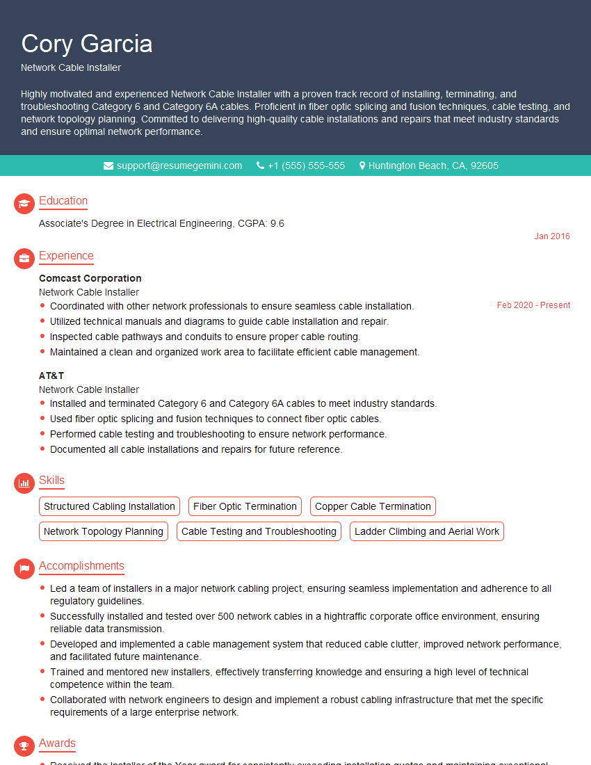
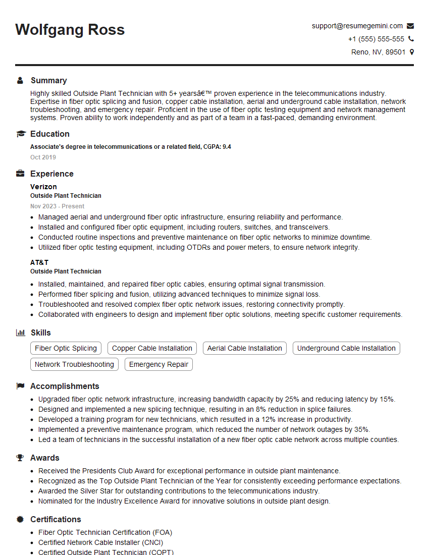
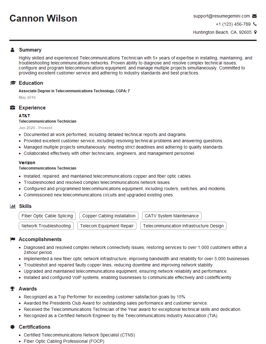
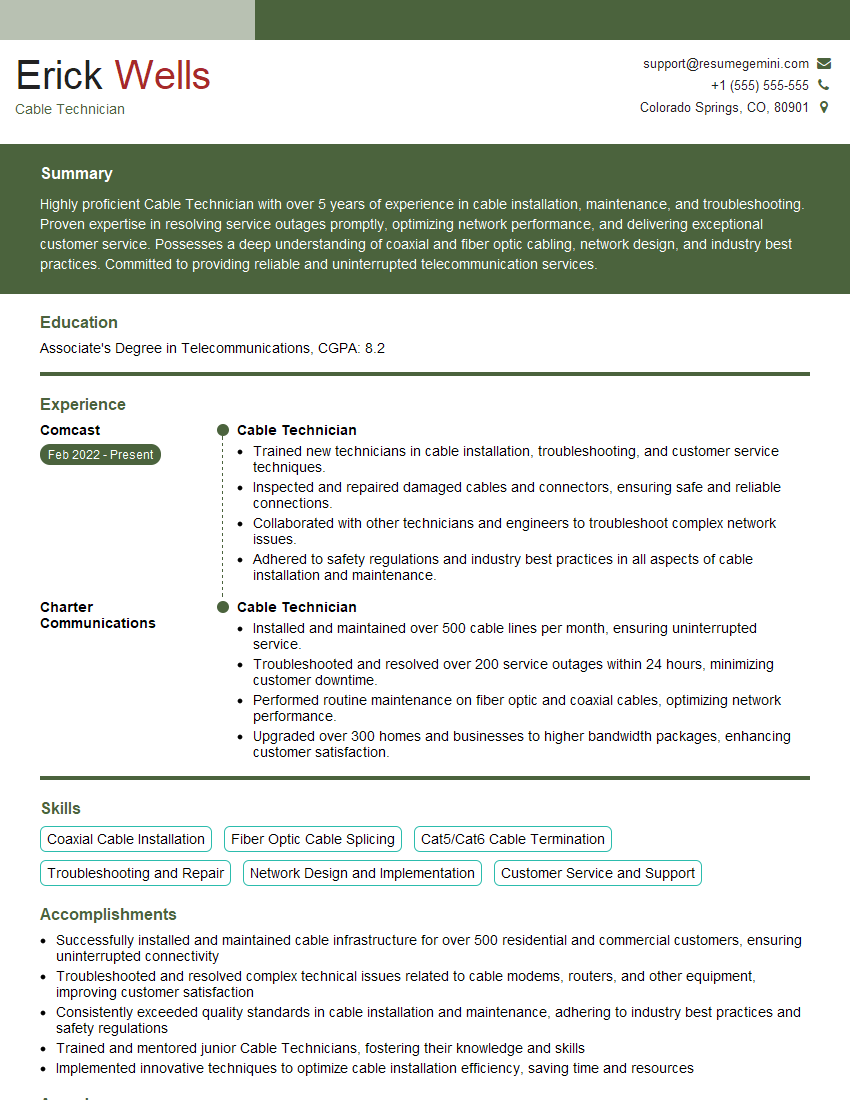
Mastering coaxial cable splicing opens doors to exciting career opportunities in various technical fields. A strong understanding of these skills is highly valued by employers and will significantly enhance your job prospects. To increase your chances of landing your dream job, create an ATS-friendly resume that effectively showcases your skills and experience. ResumeGemini is a trusted resource that can help you build a professional and impactful resume tailored to the specific requirements of the job market. We provide examples of resumes specifically designed for candidates specializing in Coaxial Cable Splicing to help guide you through the process. Invest in your future – build a powerful resume today!
Explore more articles
Users Rating of Our Blogs
Share Your Experience
We value your feedback! Please rate our content and share your thoughts (optional).
What Readers Say About Our Blog
Hello,
We found issues with your domain’s email setup that may be sending your messages to spam or blocking them completely. InboxShield Mini shows you how to fix it in minutes — no tech skills required.
Scan your domain now for details: https://inboxshield-mini.com/
— Adam @ InboxShield Mini
Reply STOP to unsubscribe
Hi, are you owner of interviewgemini.com? What if I told you I could help you find extra time in your schedule, reconnect with leads you didn’t even realize you missed, and bring in more “I want to work with you” conversations, without increasing your ad spend or hiring a full-time employee?
All with a flexible, budget-friendly service that could easily pay for itself. Sounds good?
Would it be nice to jump on a quick 10-minute call so I can show you exactly how we make this work?
Best,
Hapei
Marketing Director
Hey, I know you’re the owner of interviewgemini.com. I’ll be quick.
Fundraising for your business is tough and time-consuming. We make it easier by guaranteeing two private investor meetings each month, for six months. No demos, no pitch events – just direct introductions to active investors matched to your startup.
If youR17;re raising, this could help you build real momentum. Want me to send more info?
Hi, I represent an SEO company that specialises in getting you AI citations and higher rankings on Google. I’d like to offer you a 100% free SEO audit for your website. Would you be interested?
Hi, I represent an SEO company that specialises in getting you AI citations and higher rankings on Google. I’d like to offer you a 100% free SEO audit for your website. Would you be interested?
good
