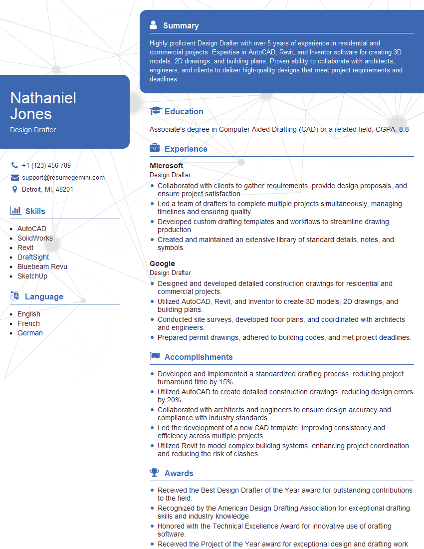
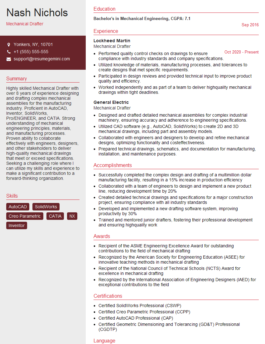
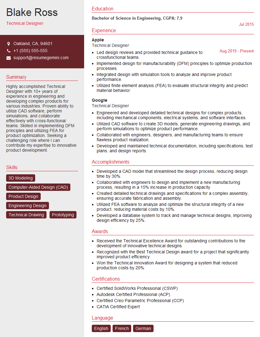
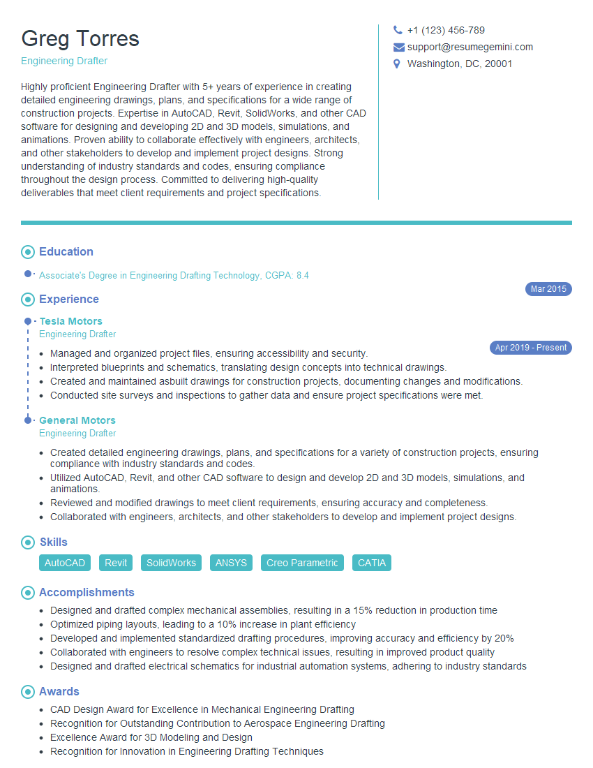
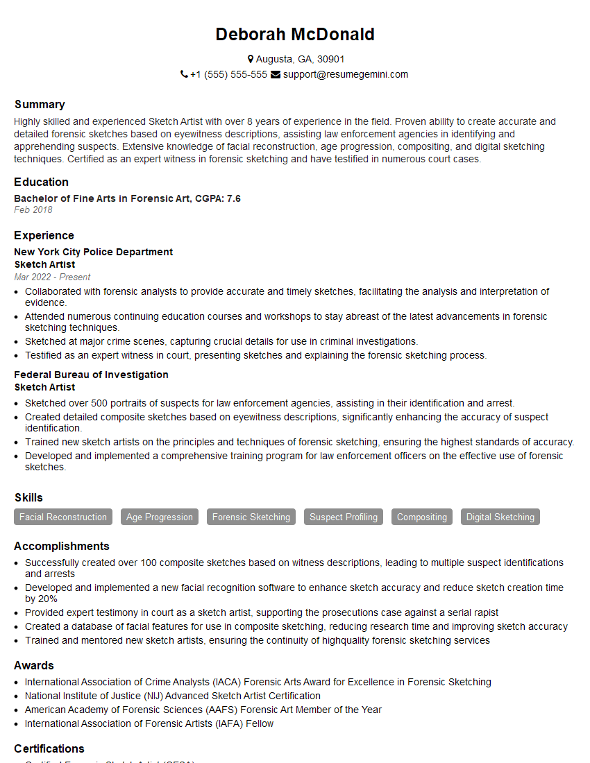
Interviews are opportunities to demonstrate your expertise, and this guide is here to help you shine. Explore the essential Drafting and Sketching interview questions that employers frequently ask, paired with strategies for crafting responses that set you apart from the competition.
Questions Asked in Drafting and Sketching Interview
Q 1. Explain your experience with different CAD software (AutoCAD, Revit, SketchUp, etc.).
My experience with CAD software is extensive, encompassing a range of programs crucial for diverse drafting and design needs. I’m highly proficient in AutoCAD, utilizing its powerful 2D drafting capabilities for precise plans, sections, and details. I frequently employ AutoCAD’s features like dynamic blocks and external references to streamline workflow and manage complex projects. My Revit experience centers on building information modeling (BIM), where I leverage its 3D modeling capabilities for creating detailed architectural, structural, and MEP models. This allows for coordinated design and effective clash detection, crucial for large-scale projects. I also have practical experience with SketchUp, primarily for conceptual design and quick 3D visualizations. Its intuitive interface and ease of use make it ideal for initial design explorations and client presentations. I’m familiar with other programs like SolidWorks and MicroStation, though my expertise lies in the previously mentioned software due to extensive project experience.
Q 2. Describe your proficiency in 2D and 3D drafting.
My proficiency in both 2D and 3D drafting is a key strength. In 2D, I’m adept at producing precise technical drawings, including floor plans, elevations, sections, and detailed drawings using various CAD software. I understand the importance of adhering to drafting standards, including layering, linetypes, and annotation techniques, to ensure clarity and consistency. My 3D drafting skills are equally strong. I use 3D modeling software to create realistic representations of designs, enabling better visualization and analysis of spatial relationships. For example, in a recent project, I used Revit to model a complex building, allowing us to identify and resolve potential construction clashes before they became costly issues on-site. This transition between 2D and 3D is seamless for me, understanding that 2D drawings often originate from or feed into 3D models.
Q 3. How do you ensure accuracy and precision in your drawings?
Accuracy and precision are paramount in drafting. I ensure this through a multi-pronged approach. Firstly, I meticulously follow design specifications and adhere strictly to industry standards and client requirements. Secondly, I leverage the tools within the CAD software to maintain precision. This includes using constraints, dimensional constraints and precise coordinate input where applicable. For instance, I regularly utilize the snap and osnap functions in AutoCAD to guarantee accurate point placement and alignment. Thirdly, I perform thorough quality checks, including visual inspections and dimensional verifications. I also utilize the software’s measurement and analysis tools to identify and correct any discrepancies. Finally, documenting my work using version control systems and maintaining detailed records ensures traceability and easy modification, preventing errors from propagating.
Q 4. What are your preferred methods for creating technical drawings?
My preferred methods for creating technical drawings depend on the project’s complexity and requirements. For straightforward projects, I might start with hand sketches to quickly explore design concepts before moving to a digital CAD environment. For complex projects, I usually start directly in a CAD software like Revit or AutoCAD. My process often involves layering for organization, employing consistent line weights and styles according to relevant standards (like ANSI or ISO), and meticulously annotating the drawings with dimensions, notes, and specifications. I always prioritize clear communication through visual clarity and consistent annotation. I frequently use templates and styles to ensure consistency and efficiency across multiple drawings.
Q 5. Explain your process for interpreting design specifications.
Interpreting design specifications is a critical first step. I begin by thoroughly reviewing all provided documents, including written specifications, reference drawings, and client briefs. I meticulously examine details such as dimensions, materials, construction methods, and relevant codes. If ambiguities or conflicts arise, I promptly communicate with the design team to clarify these issues before proceeding. I often create a detailed checklist to ensure all aspects of the specifications are understood and incorporated into the drawings. This systematic approach minimizes errors and ensures the final drawings accurately reflect the client’s vision.
Q 6. How do you handle revisions and updates to existing drawings?
Handling revisions and updates is a standard part of the design process. I employ a version control system to track all changes, allowing me to easily revert to previous versions if needed. I use revision clouds to clearly highlight modifications on the drawings themselves. These clouds are annotated with revision numbers and descriptions of changes. This system ensures clear communication of updates to the project team and clients. The use of revision logs, including dates, authors, and descriptions, ensures complete audit trails. This ensures transparency and accountability throughout the revision process, preventing confusion and ensuring project consistency.
Q 7. Describe your experience with creating detailed construction drawings.
I have significant experience creating detailed construction drawings for various projects, ranging from residential to commercial buildings. This involves producing comprehensive sets of drawings that accurately represent the design intent and provide all the necessary information for construction. This includes floor plans, elevations, sections, details, schedules, and specifications. My focus is always on clarity and completeness, ensuring that contractors have all the information needed to build the project correctly and efficiently. I pay close attention to detail, ensuring dimensions are accurate, materials are clearly specified, and construction methods are properly depicted. For example, in a recent project, I created detailed shop drawings for custom metalwork, collaborating closely with the fabricator to ensure a precise and buildable design.
Q 8. How familiar are you with industry standards and building codes?
My familiarity with industry standards and building codes is extensive. I’ve worked extensively with codes like IBC (International Building Code), NFPA (National Fire Protection Association) codes, and various local jurisdictional codes. Understanding these codes isn’t just about compliance; it’s about ensuring safety and building structures that meet the highest standards. For example, I recently worked on a project requiring specific fire-resistance ratings for wall assemblies, necessitating deep knowledge of NFPA codes to ensure the design met the required safety regulations. I regularly consult and stay updated on the latest revisions of these codes through professional development and online resources to maintain my proficiency and ensure our designs are always current and compliant.
Beyond codes, I’m proficient with industry standards related to drafting practices, including ASME Y14.5 (Dimensioning and Tolerancing) and ISO standards for technical drawings. This ensures consistency, clarity, and professional quality in all my work, making it easily understood by other professionals across different disciplines.
Q 9. Explain your approach to troubleshooting errors in your drawings.
Troubleshooting errors in drawings is a systematic process for me. I approach it like solving a puzzle, starting with a careful review of the drawing itself. This often involves zooming in to identify inconsistencies or omissions. I then compare the drawing against project specifications, ensuring consistency between the design and the client’s needs.
- Visual Inspection: This is the first step – thoroughly examining the drawing for obvious errors like dimension mismatches, conflicting annotations, or missing details.
- Cross-referencing: I compare the drawing with other related documents, such as specifications, calculations, and other drawings, to check for any discrepancies.
- Software Tools: I leverage built-in error-checking tools within my CAD software, which often highlight potential problems like overlapping lines or incorrect layering.
- Consultation: If the error persists, I don’t hesitate to consult with other team members – engineers, architects, or other drafters – for a fresh perspective.
For instance, I once discovered a clash between MEP (Mechanical, Electrical, Plumbing) systems and structural elements during a review. This was solved through collaboration with the MEP engineer, adjusting the routing of the pipes to avoid the conflict. My systematic approach ensures that errors are identified and resolved quickly and efficiently, preventing costly mistakes down the line.
Q 10. How do you collaborate with other team members on design projects?
Collaboration is crucial in design. I use a variety of methods to ensure smooth teamwork. We utilize cloud-based platforms like BIM 360 or similar systems to share models and drawings in real-time. This allows multiple users to work concurrently, eliminating version control issues. Regular team meetings, both in person and virtually, are key to discussing progress, addressing challenges, and ensuring everyone is on the same page. These meetings often include reviewing drawings, discussing design changes, and assigning tasks. Clear and concise communication, both written and verbal, is essential for avoiding misunderstandings and maintaining project momentum.
For example, on a recent large-scale project, we used a centralized model to coordinate between architectural, structural, and MEP teams. Any changes made by one team were instantly visible to others, preventing design clashes and ensuring a coordinated design. I believe a collaborative environment fosters creativity and results in a higher-quality end product.
Q 11. Describe your experience with creating presentation drawings.
Creating presentation drawings requires a different approach than technical drawings. The goal is to communicate design concepts clearly and effectively to a non-technical audience, like clients or stakeholders. I use high-quality rendering techniques to create visually appealing images. Clean linework, appropriate use of color, and strategically placed annotations are vital. I typically incorporate perspective views, cutaways, and detailed renderings to showcase the design’s key features and aesthetics. The final product needs to be clear, concise and impactful, easily communicating the design’s essence, rather than focusing on technical detail.
For example, I recently prepared a presentation for a client showcasing a new residential design. We used high-quality renderings to depict the exterior and interior spaces, focusing on the materials, lighting, and overall ambiance. The client was able to visualize the finished project easily and appreciated the professional presentation.
Q 12. How do you manage large and complex drawing files?
Managing large and complex drawing files requires a strategic approach. I rely on techniques like file organization and efficient model management. This includes organizing drawings into logical folders and using a naming convention that is clear and consistent. I use data linking effectively so that all project files are connected, ensuring any change in one automatically updates the others. The use of xrefs (external references) for repetitive details is crucial to prevent excessive file size growth. My CAD software also allows me to purge unnecessary data from files, optimizing their size without sacrificing essential information. Regular file backups are also part of my workflow to ensure data security.
For very large projects, utilizing a Building Information Modeling (BIM) platform offers significant advantages in managing the complexity and keeping the project data coordinated.
Q 13. What are your strategies for maintaining drawing organization and version control?
Maintaining drawing organization and version control is critical for efficient project management and avoiding conflicts. I employ a variety of strategies to ensure this. We utilize a central project repository, such as a cloud-based platform, allowing all team members access to the most up-to-date files. A clear version control system is implemented, using version numbers or revision dates to track changes, ensuring traceability of all modifications. Regular backups are performed to prevent data loss, following a schedule appropriate to the project size and complexity. Furthermore, a standardized filing system and consistent file naming conventions are maintained to easily locate files.
For instance, we use a system where each drawing has a unique identifier, a revision number (e.g., Drawing 001-Rev B), and the date of revision. This allows easy tracking of changes and efficient retrieval of specific versions if needed.
Q 14. Describe your experience working with different drawing scales.
Experience with different drawing scales is fundamental to my drafting work. I’m comfortable working with various scales, from very large scales (e.g., 1:1 for detailed components) to very small scales (e.g., 1:500 for site plans). Understanding the implications of scale selection is crucial – larger scales are suitable for detailing, while smaller scales are ideal for showing the overall context of the design. I must be able to accurately calculate dimensions and annotations regardless of the chosen scale. Maintaining consistency in scaling across drawings and documents is vital to ensure the project remains accurate and coordinated. This includes ensuring that all referenced drawings are compatible in scale.
For example, I might create a 1:100 scale drawing of a building’s overall layout and then create detailed drawings of individual components at a larger scale (e.g., 1:20) for construction purposes. I’m adept at converting dimensions between scales to ensure accuracy and consistency throughout the project documentation.
Q 15. Explain your understanding of orthographic and isometric projections.
Orthographic and isometric projections are two fundamental methods for representing three-dimensional objects in two dimensions. Think of them as different ways of taking a ‘picture’ of an object.
Orthographic projection uses multiple views – typically front, top, and side – to show the object from perpendicular angles. Each view shows only two dimensions of the object. Imagine looking directly at the front, then the top, then the side of a box. Each view you see is an orthographic projection. This method is extremely precise and crucial for detailed engineering drawings because it allows for accurate measurements in each plane.
Isometric projection, on the other hand, shows a single view that attempts to represent all three dimensions simultaneously. It’s like looking at an object from a slightly elevated angle. This method provides a more visually intuitive representation of the object, often used for conceptual design or presentations where clarity and easy visualization are key. While it’s less precise for measurement than orthographic projections, it offers a quicker understanding of the overall form.
For example, designing a building would use orthographic projections for precise dimensions in the blueprints, but isometric projections might be used in a presentation to showcase the building’s overall design and relationship with its surroundings.
Career Expert Tips:
- Ace those interviews! Prepare effectively by reviewing the Top 50 Most Common Interview Questions on ResumeGemini.
- Navigate your job search with confidence! Explore a wide range of Career Tips on ResumeGemini. Learn about common challenges and recommendations to overcome them.
- Craft the perfect resume! Master the Art of Resume Writing with ResumeGemini’s guide. Showcase your unique qualifications and achievements effectively.
- Don’t miss out on holiday savings! Build your dream resume with ResumeGemini’s ATS optimized templates.
Q 16. How do you handle conflicting design requirements?
Conflicting design requirements are inevitable. My approach involves a systematic process of prioritization and compromise. First, I’d clearly define all conflicting requirements, identifying the source of each. Then, I’d assess the impact of each requirement on the overall design, considering factors such as functionality, cost, and aesthetics. Often, a simple prioritization matrix can be helpful – weighting each requirement based on importance. This allows for a clear visual of what to focus on.
Sometimes, compromises are necessary. This may involve exploring alternative design solutions that can meet most of the requirements, or even revisiting the initial brief with stakeholders to clarify or re-prioritize. Effective communication throughout this process is crucial, ensuring everyone understands the trade-offs and agrees on the final solution. I’ve found that using collaborative design software facilitates clear discussions and makes managing these conflicts much easier.
For instance, in designing a piece of furniture, a client might want both maximum storage and a minimalist aesthetic. These are sometimes conflicting. I would explore various design solutions that maximize storage while using space-saving techniques to maintain a minimalist visual. Compromise might mean slightly reducing storage capacity to achieve a more streamlined look.
Q 17. What is your experience with creating detailed sections, elevations, and plans?
Creating detailed sections, elevations, and plans is a cornerstone of my drafting skills. Sections expose the internal structure of an object by cutting through it, showing hidden details. Elevations are essentially a vertical, ‘side-on’ view, showcasing the height and exterior details. Plans provide a top-down view, mapping out the layout and spatial relationships within a structure.
My experience encompasses creating these drawings for a wide range of projects, from small-scale furniture design to large-scale architectural projects. I’m proficient in using various software to create accurate, dimensionally correct drawings. I understand the importance of using standard conventions like line weights and hatching to clearly represent different materials and components. For instance, I’ve used AutoCAD to create detailed architectural plans showcasing spatial arrangements, material specifications and structural elements, and I’ve used SketchUp to create detailed sections and elevations for furniture designs showcasing internal structures and joinery details.
Beyond the technical skills, I also place a strong emphasis on clear communication through annotation. Each drawing includes clear labeling and callouts to ensure unambiguous understanding.
Q 18. How do you ensure your drawings are clearly labeled and annotated?
Clear labeling and annotation are essential for the usability and accuracy of any drawing. My approach to this involves adhering to industry standards and best practices while tailoring the level of detail to the specific audience and purpose of the drawing.
I use a consistent system of layering, ensuring all elements are clearly organized and easily identifiable. Text labels use a standard font size and style, making them legible and consistent. Dimension lines are placed accurately and clearly show units of measurement. Leader lines effectively connect labels to the specific features they refer to. For complex drawings, a comprehensive legend is provided, explaining the various symbols and notations used.
For example, when creating architectural plans, I would meticulously label all rooms, walls, doors, and windows with accurate dimensions. I’d use a specific symbol to indicate plumbing fixtures and another for electrical outlets. The legend would clearly define each symbol, ensuring the drawing is easily interpreted by anyone who might review or use it.
Q 19. Describe your experience using different drafting tools (both physical and digital).
My experience with drafting tools spans both traditional and digital methods. I’m proficient in using traditional instruments such as drafting boards, T-squares, triangles, scales, compasses, and various drawing pens. This foundational experience instilled in me a deep understanding of geometric principles and precision drafting techniques.
My digital skills include proficiency in industry-standard software like AutoCAD, Revit, SketchUp, and Adobe Illustrator. I’m adept at creating 2D and 3D models, generating detailed drawings, and manipulating complex geometries. I understand the strengths and limitations of each software, allowing me to choose the most appropriate tool for a given project. For instance, I might use Revit for complex architectural modeling, then export the views to AutoCAD to add specific details.
Beyond software, I also utilize digital pen tablets to enhance precision and control when creating drawings digitally.
Q 20. How do you stay up-to-date with the latest software and industry best practices?
Staying current in this rapidly evolving field requires a multi-pronged approach. I regularly attend industry conferences and workshops, keeping abreast of new software updates and emerging technologies. I actively participate in online forums and communities dedicated to drafting and design, engaging with professionals and learning from their experiences.
I subscribe to relevant industry publications and online resources, staying informed about best practices, new techniques, and evolving standards. I also invest time in self-learning, exploring tutorials and online courses to master new software features and techniques. Continuous learning through these methods ensures that my skills remain relevant and adaptable to the changing demands of the industry.
For example, recently I completed an online course on the latest features of Revit, improving my efficiency in creating complex building information models (BIM).
Q 21. What methods do you use for checking your work for errors?
Error checking is a critical step in my workflow. My methods combine careful self-review with systematic techniques. I begin by conducting a thorough visual inspection of my drawings, checking for inconsistencies in line weights, dimensions, and labeling. I then use the software’s built-in tools to check for dimensional errors and geometry inconsistencies.
I also employ peer review whenever possible, having another draftsperson review my work for errors or areas for improvement. This provides a fresh perspective and often helps identify errors I might have overlooked. Finally, I maintain a detailed revision history, documenting all changes and corrections. This allows me to trace any issues back to their source and ensures the final drawings are accurate and complete.
For complex projects, a checklist can help ensure nothing is missed during the review process. For example, I’ll create a checklist specifying items to check (e.g., dimension accuracy, material notations, compliance with building codes).
Q 22. Explain your experience with creating detailed assembly drawings.
Creating detailed assembly drawings requires a methodical approach combining technical skill and spatial reasoning. I begin by thoroughly understanding the assembly’s function and the individual components. This often involves reviewing design specifications, collaborating with engineers, and sometimes even physically examining prototypes. My process then involves:
- Component Breakdown: First, I meticulously list each component, noting its material, dimensions, and manufacturing process.
- Exploded View Sketching: I create a preliminary exploded view sketch to visualize the assembly sequence and spatial relationships between parts. This helps ensure clarity and avoids conflicts during the detailed drawing phase.
- Detailed Drawing Creation: I then use CAD software (AutoCAD, SolidWorks, etc., depending on project requirements) to create detailed orthographic projections, including views like front, side, top, and section views as needed. Each component is precisely dimensioned and annotated with tolerances and material specifications.
- Bill of Materials (BOM): A comprehensive BOM is created and linked to the drawing, specifying part numbers, quantities, and material descriptions for each component.
- Revision Control: I maintain strict revision control using a versioning system to track changes and ensure everyone works from the most up-to-date version.
For example, in a recent project involving a complex robotic arm assembly, I created a detailed assembly drawing with over 50 components, ensuring that manufacturing tolerances were accurately defined to guarantee smooth operation and avoid assembly errors.
Q 23. How do you create effective and communicative sketches for design concepts?
Effective design sketches communicate ideas clearly and concisely, even before detailed drawings are produced. My approach emphasizes clarity, proportion, and visual appeal. I start with loose, gestural sketches to explore design options, focusing on form and function. Then, I refine these into more detailed sketches that communicate specific design features.
- Perspective & Proportion: I pay close attention to perspective and proportion to create a realistic and believable representation of the design.
- Line Weight & Shading: Using varying line weights and shading techniques helps to highlight important features and create depth and visual interest. I avoid clutter by using only necessary lines and details.
- Annotations: I add concise annotations to clarify design decisions or highlight specific features. This ensures that anyone reviewing the sketches understands the design intent.
- Iteration & Feedback: Sketching is an iterative process. I frequently review and refine my sketches, incorporating feedback from collaborators and stakeholders.
Imagine sketching a new chair design. A quick initial sketch might focus on the overall shape and proportions. Then, more refined sketches might show specific details like the joinery between the legs and seat, the curvature of the backrest, and the material texture.
Q 24. Describe your understanding of dimensioning and tolerancing.
Dimensioning and tolerancing are crucial for ensuring that a design can be manufactured consistently and meets its functional requirements. Dimensioning provides the exact sizes and locations of features, while tolerancing specifies the acceptable range of variation for those dimensions. Understanding geometric dimensioning and tolerancing (GD&T) is essential for communicating manufacturing requirements precisely.
- Dimensioning: This involves adding numerical values to drawings to indicate the sizes, lengths, angles, and other relevant parameters of parts and assemblies. Proper dimensioning practices involve using appropriate standards and avoiding redundant or conflicting dimensions.
- Tolerancing: This defines acceptable limits of variation in dimensions and form. Tolerances are expressed using various methods, including plus/minus values, limit dimensions, and GD&T symbols. GD&T employs symbols to specify tolerances on features like straightness, flatness, circularity, and position. The choice of tolerancing method depends on the application and manufacturing process.
For example, specifying a hole diameter as “10.00 ± 0.05mm” means the hole can range from 9.95mm to 10.05mm and still be acceptable. Using GD&T, one might specify the position tolerance of that hole relative to other features, allowing for more flexibility in manufacturing while ensuring proper functionality.
Q 25. How do you handle tight deadlines and pressure?
Handling tight deadlines and pressure requires effective time management, prioritization, and a calm approach. I thrive under pressure but recognize the importance of strategic planning and resource allocation. My strategies include:
- Prioritization: I identify critical tasks and prioritize them based on deadlines and impact. This allows me to focus my efforts on the most important aspects of the project first.
- Time Management: I use project management tools and techniques (like Gantt charts or Kanban) to break down large projects into smaller, manageable tasks with realistic timelines. This ensures steady progress and helps identify potential bottlenecks early on.
- Communication: Open communication with clients and team members is essential. If I encounter unexpected delays or roadblocks, I proactively communicate these to stakeholders to prevent surprises and ensure effective collaboration.
- Stress Management: While pressure is inevitable, I maintain a calm and focused approach. I take short breaks, prioritize my well-being, and utilize relaxation techniques to avoid burnout.
I remember one instance where a major project’s deadline was unexpectedly accelerated. By focusing my efforts, delegating certain tasks where possible, and maintaining open communication, I successfully delivered the drawings on time and to specification.
Q 26. Explain your experience with creating drawings for different building types (residential, commercial, industrial).
My experience spans various building types, each with unique drawing requirements and standards.
- Residential: I’ve worked on residential projects ranging from single-family homes to multi-unit dwellings. Drawings typically include floor plans, elevations, sections, and details showing construction methods, material specifications, and plumbing/electrical layouts.
- Commercial: Commercial projects require more detailed and complex drawings, including site plans, floor plans, elevations, structural drawings, and MEP (mechanical, electrical, and plumbing) plans. These need to adhere to stringent building codes and regulations.
- Industrial: Industrial projects often involve large-scale structures and specialized equipment. Drawings might include detailed site plans, structural analysis drawings, equipment layouts, and piping and instrumentation diagrams (P&IDs).
The key difference lies in the scale and complexity of the projects. Residential drawings are generally simpler, while commercial and industrial projects demand precision and rigorous adherence to industry standards and regulations. I am proficient in using different software and adapting my style to fit specific project needs.
Q 27. What is your experience with creating shop drawings?
Shop drawings are detailed, technical drawings used by fabricators and contractors during construction. They provide precise dimensions, specifications, and installation details to ensure accurate construction. My experience includes:
- Reviewing Design Documents: I begin by thoroughly reviewing architectural and engineering drawings to understand the design intent and specifications.
- Creating Fabrication Drawings: I then create detailed drawings for each component, specifying dimensions, materials, and finishes. This ensures accuracy and consistency.
- Coordination and Collaboration: I collaborate with fabricators and contractors to resolve any conflicts or discrepancies between the design documents and the shop drawings. This coordination is key to successful construction.
- Checking for Compliance: I ensure that shop drawings adhere to all relevant building codes, industry standards, and client specifications.
In a recent project, I prepared shop drawings for custom metalwork components for a commercial building. My accurate shop drawings ensured seamless installation and avoided costly rework during construction.
Q 28. How would you approach creating a drawing from a verbal description?
Creating drawings from verbal descriptions requires active listening, visualization skills, and careful questioning. I adopt a systematic approach:
- Clarification and Questioning: I begin by asking clarifying questions to fully understand the design intent, including dimensions, materials, and functional requirements. I encourage the client to describe the design from different perspectives.
- Sketching and Visualization: I create preliminary sketches to visualize the design based on the verbal description. This helps to clarify ambiguities and identify potential conflicts.
- Refining the Drawings: I refine the sketches into more detailed drawings, using appropriate tools and techniques, incorporating necessary annotations and dimensions.
- Confirmation and Feedback: I present the refined drawings to the client for review and feedback, ensuring that the final drawings accurately reflect their design vision.
Imagine someone describing a simple bookshelf. I would ask about the dimensions, the number of shelves, the material, and the desired style. I would then create a rough sketch, refine it based on feedback, and finalize the drawing with precise dimensions and annotations.
Key Topics to Learn for Drafting and Sketching Interview
- Fundamentals of Drafting: Understanding drawing instruments, scales, lettering standards, and orthographic projections. Practice applying these to create accurate and detailed technical drawings.
- Sketching Techniques: Mastering freehand sketching, perspective drawing, and sketching from observation. Develop your ability to quickly communicate design ideas through effective sketches.
- CAD Software Proficiency: Demonstrate familiarity with industry-standard CAD software (AutoCAD, Revit, etc.). Be prepared to discuss your experience with 2D and 3D modeling, drafting tools, and file management.
- Blueprint Reading and Interpretation: Practice interpreting complex blueprints, identifying dimensions, materials, and specifications. Highlight your ability to understand and extract information from technical drawings.
- Dimensioning and Tolerancing: Understand geometric dimensioning and tolerancing (GD&T) principles and their application in creating precise and unambiguous drawings. Be ready to explain how tolerances affect manufacturing processes.
- Design Principles and Applications: Discuss your understanding of design principles like ergonomics, aesthetics, and functionality. Be prepared to explain how drafting and sketching contribute to successful product design.
- Problem-Solving and Critical Thinking: Show how you approach technical challenges using your drafting and sketching skills. Prepare examples demonstrating your ability to troubleshoot design issues and find effective solutions.
- Communication and Collaboration: Highlight your ability to effectively communicate technical information through drawings and collaborate with other professionals in a design team environment.
Next Steps
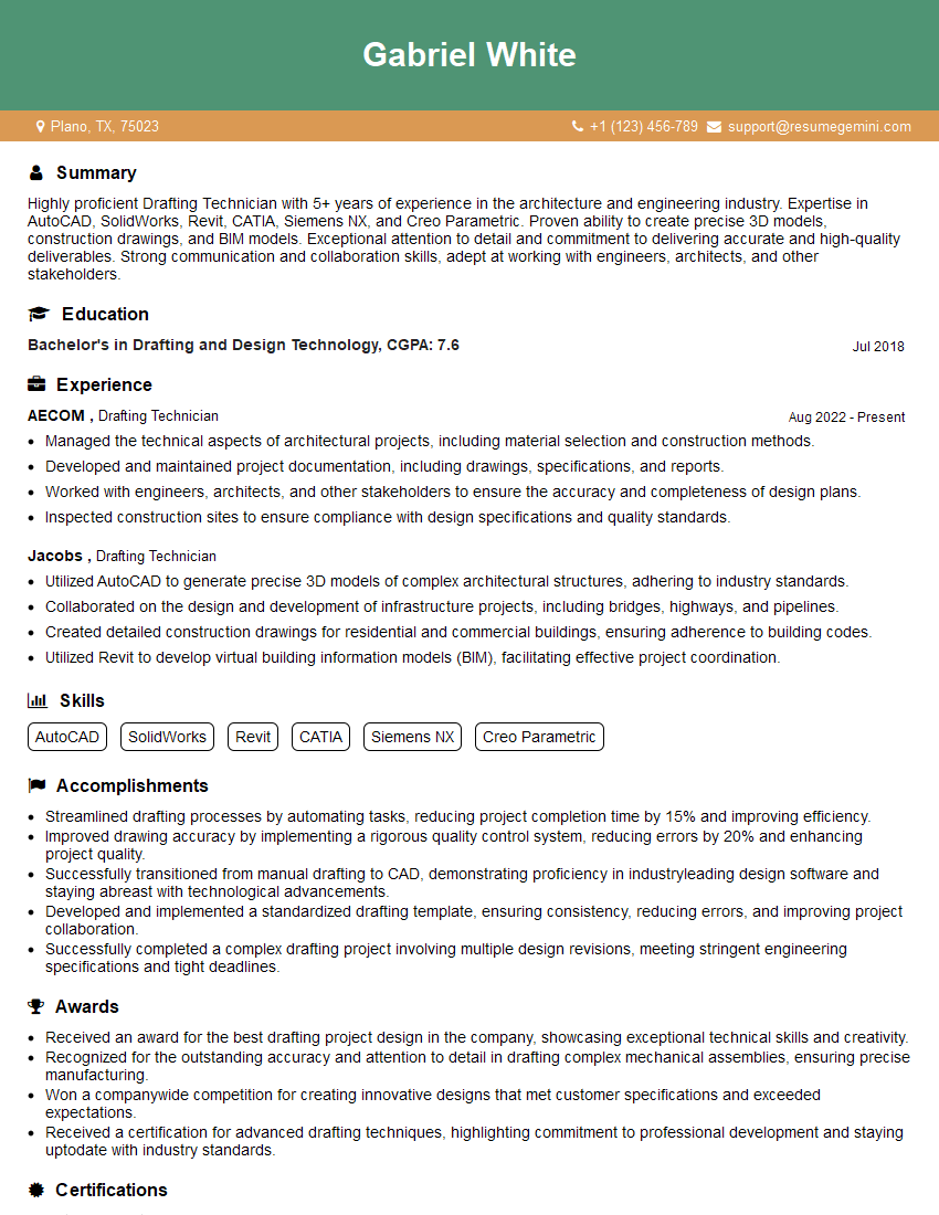
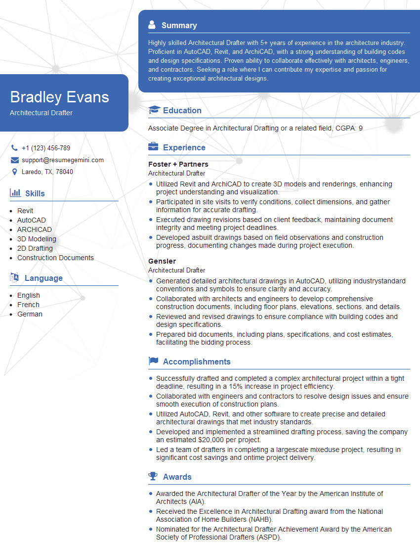
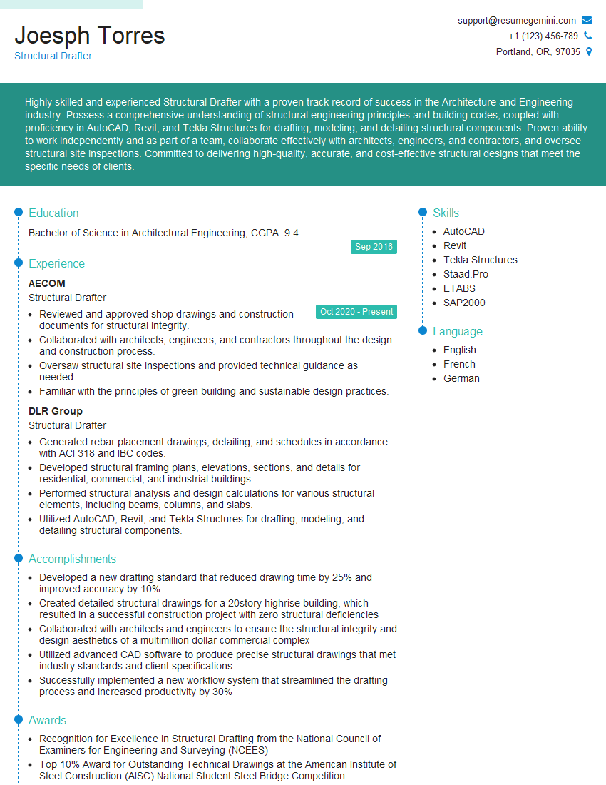
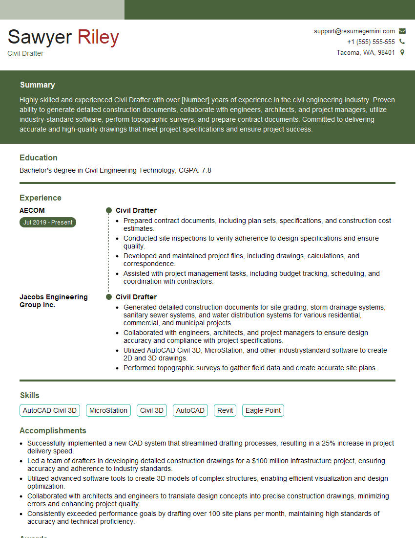
Mastering drafting and sketching is crucial for a successful career in many fields, opening doors to exciting opportunities in engineering, architecture, and design. A strong foundation in these skills demonstrates attention to detail, problem-solving abilities, and effective communication – all highly valued attributes by employers. To enhance your job prospects, create an ATS-friendly resume that highlights your technical skills and experience. We strongly encourage you to leverage ResumeGemini, a trusted resource for building professional resumes. ResumeGemini provides examples of resumes tailored specifically to Drafting and Sketching professionals, ensuring your application stands out. Take the next step in your career journey today!
Explore more articles
Users Rating of Our Blogs
Share Your Experience
We value your feedback! Please rate our content and share your thoughts (optional).
What Readers Say About Our Blog
Hello,
We found issues with your domain’s email setup that may be sending your messages to spam or blocking them completely. InboxShield Mini shows you how to fix it in minutes — no tech skills required.
Scan your domain now for details: https://inboxshield-mini.com/
— Adam @ InboxShield Mini
Reply STOP to unsubscribe
Hi, are you owner of interviewgemini.com? What if I told you I could help you find extra time in your schedule, reconnect with leads you didn’t even realize you missed, and bring in more “I want to work with you” conversations, without increasing your ad spend or hiring a full-time employee?
All with a flexible, budget-friendly service that could easily pay for itself. Sounds good?
Would it be nice to jump on a quick 10-minute call so I can show you exactly how we make this work?
Best,
Hapei
Marketing Director
Hey, I know you’re the owner of interviewgemini.com. I’ll be quick.
Fundraising for your business is tough and time-consuming. We make it easier by guaranteeing two private investor meetings each month, for six months. No demos, no pitch events – just direct introductions to active investors matched to your startup.
If youR17;re raising, this could help you build real momentum. Want me to send more info?
Hi, I represent an SEO company that specialises in getting you AI citations and higher rankings on Google. I’d like to offer you a 100% free SEO audit for your website. Would you be interested?
Hi, I represent an SEO company that specialises in getting you AI citations and higher rankings on Google. I’d like to offer you a 100% free SEO audit for your website. Would you be interested?
good
