Every successful interview starts with knowing what to expect. In this blog, we’ll take you through the top Electrical Wiring and Control interview questions, breaking them down with expert tips to help you deliver impactful answers. Step into your next interview fully prepared and ready to succeed.
Questions Asked in Electrical Wiring and Control Interview
Q 1. Explain the difference between AC and DC current.
The fundamental difference between AC (Alternating Current) and DC (Direct Current) lies in the direction of electron flow. In DC, electrons flow consistently in one direction, like a river flowing downstream. This is the type of current produced by batteries. AC, on the other hand, periodically reverses its direction of flow, oscillating back and forth like a wave in the ocean. This is the type of electricity that powers our homes and businesses.
Think of it like this: a water pump pushing water in one direction continuously is like DC. A piston pump that pushes and pulls water alternately is like AC. This cyclical nature of AC allows for efficient long-distance transmission through transformers, reducing power loss.
Practically, DC is used in applications requiring a constant voltage, such as charging batteries or powering electronic devices. AC is ubiquitous in power grids due to its ease of transformation and distribution. The difference is critical in choosing the appropriate components and equipment for electrical systems.
Q 2. Describe the function of a circuit breaker.
A circuit breaker is a safety device designed to protect an electrical circuit from damage caused by excessive current flow. It acts as an automatic switch, interrupting the circuit when the current exceeds a predetermined threshold. This prevents overheating, fires, and equipment damage. Essentially, it’s a fast-acting safety valve for your electrical system.
Imagine a pipe carrying water under high pressure. If the pressure gets too high, the pipe could burst. A circuit breaker is like a pressure relief valve that automatically shuts off the water flow before the pipe bursts. Different circuit breakers are rated for different current capacities, so selecting the appropriate breaker for a given circuit is critical.
Circuit breakers use either thermal or electromagnetic mechanisms or a combination of both, to detect overcurrent conditions. When triggered, they trip, cutting off the power. They can then be manually reset once the problem has been resolved.
Q 3. What are the different types of wiring conduits?
Wiring conduits protect electrical wiring from physical damage and environmental hazards. Several types exist, each with its own advantages and disadvantages:
- Rigid Metal Conduit (RMC): Strong and durable, suitable for harsh environments. It’s often used for outdoor installations or where high mechanical protection is needed.
- Intermediate Metal Conduit (IMC): Lighter and easier to install than RMC, but still provides good protection. A good compromise between strength and ease of installation.
- Electrical Metallic Tubing (EMT): Also known as thin-wall conduit, it’s lightweight and flexible, making it ideal for indoor applications. It’s less protective than RMC or IMC but significantly easier to work with.
- Flexible Metal Conduit (FMC): Highly flexible, used for connecting equipment or in areas requiring frequent movement of the wires.
- Plastic Conduit (PVC): Lightweight, corrosion-resistant, and cost-effective. Commonly used for indoor applications where mechanical protection isn’t as critical.
The choice of conduit depends on factors such as the environment, the type of wiring, and the required level of protection.
Q 4. How do you troubleshoot a faulty circuit?
Troubleshooting a faulty circuit requires a systematic approach. Safety is paramount; always de-energize the circuit before beginning any troubleshooting.
- Visual Inspection: Begin with a thorough visual inspection of the circuit, looking for obvious problems like loose connections, damaged wires, or tripped circuit breakers.
- Voltage Testing: Use a non-contact voltage tester or a multimeter to check for voltage at various points in the circuit to identify where the problem lies. A lack of voltage could indicate a break in the circuit, while excessive voltage could indicate a short circuit.
- Continuity Testing: With the circuit de-energized, use a multimeter to test the continuity of the wires. This helps locate breaks or short circuits in the wiring.
- Component Testing: If the problem isn’t in the wiring, test individual components such as switches, outlets, and appliances to determine which one is faulty.
- Load Testing: If possible, gradually increase the load on the circuit to see if it trips the breaker. This can help pinpoint the cause of overloading.
Detailed documentation and organized testing are key. Using a systematic method greatly reduces the time spent troubleshooting.
Q 5. What safety precautions do you take when working with electricity?
Safety is paramount when working with electricity. Never compromise on safety procedures. Here are key precautions:
- De-energize the Circuit: Always disconnect the power source before working on any electrical circuit. Use a lockout/tagout system to prevent accidental re-energization.
- Use Proper Personal Protective Equipment (PPE): Wear insulated gloves, safety glasses, and appropriate footwear. Consider a safety harness for working at heights.
- Use Insulated Tools: Ensure all tools are insulated to prevent electrical shock.
- Be Aware of Surroundings: Keep a safe distance from overhead power lines and other potential hazards.
- Follow Electrical Codes: Adhere to all relevant electrical codes and regulations.
- Never Work Alone: Always have a colleague present to assist in case of an emergency.
Remember that even seemingly low voltages can be dangerous. A moment of carelessness can lead to serious injury or even death.
Q 6. Explain Ohm’s Law and its applications.
Ohm’s Law describes the relationship between voltage (V), current (I), and resistance (R) in an electrical circuit. It states: V = I * R
Voltage (V) is the electrical potential difference, measured in volts. Current (I) is the flow of electrical charge, measured in amperes. Resistance (R) is the opposition to the flow of current, measured in ohms.
Applications:
- Calculating Voltage Drop: Ohm’s Law helps calculate the voltage drop across a component or a section of a circuit. This is crucial for designing circuits to ensure components receive the correct voltage.
- Determining Circuit Current: Knowing the voltage and resistance, Ohm’s Law allows us to calculate the current flowing through a circuit. This helps determine the appropriate size of wires and circuit breakers.
- Calculating Resistance: If the voltage and current are known, Ohm’s Law can be used to calculate the resistance of a component. This is essential for troubleshooting and determining the health of electrical components.
Ohm’s Law is a fundamental principle in electrical engineering, used extensively in circuit design, analysis, and troubleshooting.
Q 7. What is a PLC and how does it work?
A PLC (Programmable Logic Controller) is a digital computer used for automated control of electromechanical processes such as those found in manufacturing. Think of it as the brain of an automated system.
How it works: A PLC receives input signals from sensors and switches, processes these inputs according to a programmed logic, and outputs control signals to actuators like motors, valves, and lights. The program is typically written using ladder logic, a graphical programming language easily understood by electrical technicians.
Example: Imagine a conveyor belt system in a factory. Sensors detect the presence of parts on the belt. A PLC program monitors these sensors. If a part is detected, the PLC activates a motor to move the part to the next stage of the production process. If no part is detected, the motor remains off. PLCs are used across many industries for increased efficiency and safety in automated processes.
In short, PLCs simplify complex control systems through easily programmable logic, leading to robust and reliable automation solutions.
Q 8. Describe different types of sensors used in control systems.
Sensors are the eyes and ears of any control system, providing crucial information about the system’s environment or internal state. They convert physical phenomena like temperature, pressure, light, or motion into electrical signals that a controller can understand and use to make decisions. There’s a wide variety, categorized by the physical quantity they measure.
- Temperature Sensors: Thermocouples (measuring temperature difference), RTDs (Resistance Temperature Detectors, measuring resistance change with temperature), and thermistors (similar to RTDs but with a more pronounced resistance change). For example, a thermocouple might be used in an industrial oven to monitor temperature, ensuring consistent baking.
- Pressure Sensors: Strain gauge-based sensors, piezoelectric sensors, and capacitive sensors. A pressure sensor might be used in a hydraulic system to monitor fluid pressure and prevent overpressure conditions.
- Proximity Sensors: Inductive, capacitive, and ultrasonic sensors detect the presence of objects without physical contact. These are common in robotics for obstacle avoidance or in automated manufacturing for part detection.
- Light Sensors: Photoresistors (resistance changes with light intensity), photodiodes (generate current proportional to light intensity), and phototransistors. A photoresistor might be used in a streetlight control system to activate the lights when it gets dark.
- Motion Sensors: Accelerometers (measure acceleration), gyroscopes (measure rotation), and encoders (measure angular or linear displacement). Motion sensors are critical in robotic arms for precise control and navigation.
The choice of sensor depends heavily on the specific application, considering factors like accuracy, range, response time, cost, and environmental robustness.
Q 9. Explain the concept of grounding and its importance.
Grounding, or earthing, is the connection of an electrical circuit or equipment to the earth. It’s a fundamental safety measure and crucial for proper system operation. Imagine the earth as a massive reservoir of electrons – grounding provides a low-resistance path for fault currents to flow to the earth, preventing dangerous voltage buildup and protecting equipment and personnel.
Importance:
- Safety: In the event of a fault (e.g., a short circuit), grounding diverts fault current to the earth, minimizing the risk of electric shock. Without grounding, exposed metal parts could become live, posing a severe hazard.
- Equipment Protection: Grounding helps protect electronic equipment from voltage surges and lightning strikes by providing a path for excess energy to dissipate safely. It prevents damage to sensitive components.
- Noise Reduction: Grounding minimizes electrical noise and interference in circuits, crucial for sensitive electronics where unwanted signals can lead to malfunctions.
- System Stability: Proper grounding helps stabilize voltage levels and ensures consistent operation of electrical systems.
Grounding is achieved using ground rods driven into the earth, connected to a grounding busbar, and then to the equipment through grounding conductors. The National Electrical Code (NEC) provides detailed guidelines for proper grounding practices.
Q 10. What are the different types of relays used in control circuits?
Relays are electromechanical switches that use a small electrical current to control a much larger current. Think of them as electrically operated light switches that can handle significantly more power than a simple wall switch. Various types exist, categorized by their operating principle or application.
- Electromechanical Relays: These are the most common type, using an electromagnet to actuate mechanical contacts. They are relatively simple, robust, and inexpensive.
- Solid-State Relays (SSRs): These use semiconductor devices instead of mechanical contacts. SSRs are faster, quieter, and have longer lifespans than electromechanical relays but can be more expensive and sensitive to overvoltage conditions.
- Time-Delay Relays: These introduce a time delay before switching, useful for sequencing operations or preventing premature activation. They can be either electromechanical or solid-state.
- Overload Relays: These are safety devices that protect circuits from excessive current. They trip and disconnect the circuit if the current exceeds a predetermined threshold.
- Contactor Relays: These are heavy-duty relays designed to switch high-power loads, commonly used in motor control circuits.
The selection of a relay depends on factors like the load current, voltage, switching frequency, required speed, and environmental conditions. For instance, a contactor relay might control a large motor in an industrial setting, while a solid-state relay might be used to switch a low-voltage LED light.
Q 11. How do you interpret electrical schematics and blueprints?
Interpreting electrical schematics and blueprints requires a systematic approach and familiarity with standard symbols and conventions. Schematics are simplified diagrams showing the electrical connections and components, while blueprints provide the physical layout and dimensions. Think of a schematic as a wiring diagram and a blueprint as the construction plan.
Interpretation Steps:
- Identify the symbols: Understand the meaning of standard electrical symbols for components like resistors, capacitors, inductors, switches, relays, and motors.
- Trace the circuits: Follow the lines representing wires to trace the path of the current flow through different components.
- Understand the logic: Analyze the arrangement of components to understand the function of the circuit and how it works. Look for control loops, feedback mechanisms, and safety features.
- Refer to the legend: Many schematics include a legend or key that explains specific symbols or notations used.
- Cross-reference with blueprints: Correlate the schematic’s components with their physical locations shown on the blueprints.
For example, you might use a schematic to understand how a motor control circuit works, then refer to the blueprint to determine the physical placement of the motor, relay, and other components in the equipment.
Q 12. Describe your experience with different types of wiring diagrams.
My experience encompasses various wiring diagrams, each suited for different purposes and levels of detail. The choice of diagram depends on the complexity of the system and the audience.
- Ladder Diagrams: These are widely used in industrial control systems, representing the circuit using horizontal power rails and vertical rungs representing individual control circuits. They’re easy to understand and follow the logic of the system.
- Schematic Diagrams: These provide a more detailed representation of the electrical components and their interconnections, showing more precisely how the circuit is wired. They are useful for troubleshooting and understanding the circuit’s internal workings.
- One-Line Diagrams: These are simplified diagrams that show the main power lines and equipment connections, omitting less critical details. They are commonly used in power system studies and analysis.
- Wiring Diagrams: These show the actual physical connections of wires and terminals, providing a direct guide for installation and wiring. These diagrams are essential for technicians installing or repairing equipment.
I’ve worked extensively with all these types in various projects, from simple residential wiring to complex industrial automation systems. The ability to interpret and create different types of diagrams is essential for effective communication and efficient troubleshooting.
Q 13. What are the common causes of electrical fires?
Electrical fires are a serious hazard, often caused by a combination of factors. Understanding these causes is crucial for prevention.
- Overloaded Circuits: Drawing more current than the wiring or circuit breaker can safely handle. This leads to overheating and potential ignition of nearby materials.
- Faulty Wiring: Damaged insulation, loose connections, or improper wiring practices can create arcing, sparking, and excessive heat. This is particularly dangerous in older buildings with outdated wiring.
- Short Circuits: An unintended path for current to flow, bypassing normal circuit components. This often leads to rapid heating and can initiate a fire.
- Overheating Appliances: Appliances with faulty heating elements, overloaded motors, or insufficient ventilation can overheat and catch fire.
- Improper Grounding: Inadequate grounding can allow dangerous voltage to build up, leading to arcing and fires.
- Appliance Malfunction: Faulty appliances, such as refrigerators, washing machines, or microwaves, can become fire hazards if not repaired or replaced timely.
Regular inspection, proper maintenance, and adhering to electrical safety codes are vital in preventing electrical fires. Simple steps like not overloading outlets and replacing frayed cords can significantly reduce risk.
Q 14. Explain the NEC code and its significance in electrical work.
The National Electrical Code (NEC) is a widely adopted standard for the safe installation of electrical systems in the United States. It’s not a law itself but forms the basis for many local electrical codes and regulations. Think of it as a comprehensive rulebook ensuring safe and reliable electrical installations.
Significance:
- Safety: The NEC’s primary goal is to prevent electrical hazards, protecting people and property from fire, shocks, and other electrical dangers.
- Consistency: It provides a uniform set of standards, ensuring that electrical installations are consistent across different regions and jurisdictions.
- Compliance: Adherence to the NEC is often mandated by building codes and insurance companies, ensuring that electrical work meets minimum safety requirements.
- Liability: Electricians who violate NEC provisions can face legal and financial consequences.
The NEC is regularly updated to reflect advancements in technology and to address emerging safety concerns. Staying abreast of the latest code revisions is crucial for anyone working in the electrical field.
Q 15. What experience do you have with different types of motor controls?
My experience with motor controls spans a wide range of technologies, from simple on/off switching to sophisticated variable frequency drives (VFDs). I’ve worked extensively with:
- Direct On-Line (DOL) starters: These are the simplest, providing direct power to the motor. I’ve used them in applications requiring simple starts and stops, such as small conveyor systems. However, I understand their limitations, specifically high inrush current and mechanical stress on the motor.
- Star-Delta starters: These reduce starting current by initially connecting the motor windings in a star configuration before switching to a delta configuration for normal operation. I’ve implemented these in situations where reducing starting current was crucial, minimizing power grid disturbances.
- Autotransformers: Similar to Star-Delta starters, autotransformers reduce starting voltage, reducing inrush current. I’ve used these in applications where precise control over starting current is needed.
- Variable Frequency Drives (VFDs): My most extensive experience lies with VFDs, which offer precise speed control and soft starting capabilities. I’ve worked with VFDs in various applications, including complex HVAC systems, process control machinery, and robotics, using both scalar and vector control methods. I’m familiar with troubleshooting VFD issues such as overheating, communication errors, and parameter settings.
- Soft Starters: These provide a smooth, controlled start for AC motors, reducing stress on both the motor and power system. They are particularly useful for large motors driving high-inertia loads.
In each application, I carefully select the control method based on factors like motor size, load characteristics, required speed control, and budget constraints.
Career Expert Tips:
- Ace those interviews! Prepare effectively by reviewing the Top 50 Most Common Interview Questions on ResumeGemini.
- Navigate your job search with confidence! Explore a wide range of Career Tips on ResumeGemini. Learn about common challenges and recommendations to overcome them.
- Craft the perfect resume! Master the Art of Resume Writing with ResumeGemini’s guide. Showcase your unique qualifications and achievements effectively.
- Don’t miss out on holiday savings! Build your dream resume with ResumeGemini’s ATS optimized templates.
Q 16. How do you test for continuity and voltage?
Testing for continuity and voltage is fundamental to electrical troubleshooting. Safety is paramount – always ensure the power is OFF before conducting any tests.
Continuity Testing: This verifies the presence of a continuous, unbroken path for current flow. I use a multimeter set to the continuity mode (often symbolized by a diode). A low resistance reading (often indicated by a beep) indicates continuity. A high resistance or open circuit means a break in the wire or component.
Example: To check the continuity of a circuit breaker, I’d place the multimeter probes across the terminals. A beep confirms that the contacts are closed and the circuit is complete. An open circuit indicates a faulty breaker.
Voltage Testing: This measures the electrical potential difference between two points in a circuit. Again, I use a multimeter, this time selecting the appropriate voltage range (AC or DC, and the anticipated voltage level). I carefully probe the circuit points while ensuring I avoid touching the probes or other metallic parts.
Example: Before connecting a motor to a power supply, I’d measure the voltage at the supply terminals to confirm it matches the motor’s voltage rating. A significant deviation would indicate a problem with the power supply.
Q 17. What is a PID controller and how does it function?
A Proportional-Integral-Derivative (PID) controller is a feedback control loop mechanism widely used in industrial control systems. It aims to minimize the error between a desired setpoint and a measured process variable by adjusting a manipulated variable.
How it functions:
- Proportional (P): This term responds to the current error. A larger error results in a larger corrective action. Think of it like a thermostat: the further the temperature is from the setpoint, the harder the heater or AC works.
- Integral (I): This term addresses accumulated error over time. It corrects for persistent offsets or drifts. If the system consistently has a small error, the integral term gradually adjusts to eliminate it.
- Derivative (D): This term anticipates future error based on the rate of change of the error. It helps dampen oscillations and prevent overshoot. Think of it like braking a car – you ease off the accelerator to anticipate the stop.
The overall control action is a combination of these three terms, often expressed as:
Output = Kp * error + Ki * integral(error) + Kd * derivative(error)where Kp, Ki, and Kd are tuning constants that determine the contribution of each term. Precise tuning of these constants is crucial for optimal controller performance, avoiding oscillations and ensuring stability.
Real-world example: In a chemical process, a PID controller might maintain the temperature of a reactor by adjusting the flow rate of a coolant based on the temperature difference between the setpoint and the actual reactor temperature.
Q 18. Describe your experience with SCADA systems.
My SCADA (Supervisory Control and Data Acquisition) system experience involves both configuration and troubleshooting. I’ve worked with various SCADA platforms, including [mention specific platforms if possible, e.g., Wonderware, Siemens WinCC, Rockwell Automation FactoryTalk].
My experience includes:
- Designing and implementing HMI (Human-Machine Interface) screens: Creating intuitive interfaces for operators to monitor and control processes.
- Configuring data acquisition: Setting up communication protocols (e.g., Modbus, Profibus, Ethernet/IP) to collect data from various field devices (sensors, PLCs, etc.).
- Developing alarm management strategies: Implementing alarm prioritization and notification systems to alert operators to critical events.
- Troubleshooting communication issues: Identifying and resolving network connectivity problems and data transmission errors.
- Data analysis and reporting: Using historical data to identify trends, optimize processes, and improve efficiency.
One particular project involved implementing a SCADA system for a water treatment plant. This required integration of various sensors, PLCs, and actuators to monitor and control water flow, chemical dosing, and filtration processes. I successfully resolved a significant communication issue between the SCADA server and remote PLCs, improving real-time data visibility and operational efficiency.
Q 19. Explain the concept of short circuits and open circuits.
Short Circuit: A short circuit, or short, is an unintended low-resistance path for current to flow, typically caused by faulty insulation, damaged wiring, or accidental contact between conductors. This leads to excessive current flow, which can generate significant heat and potentially cause fire or equipment damage. Think of it like creating a shortcut in a river, causing a massive surge of water in the new, shorter path.
Open Circuit: An open circuit occurs when a break in the electrical path prevents current from flowing. This can be due to a broken wire, a faulty switch, or a burned-out component. It’s like a dam blocking the flow of water in a river.
Consequences: Short circuits can cause significant damage, while open circuits result in a lack of functionality. Both require careful troubleshooting and repair to ensure safety and proper operation.
Q 20. How do you handle electrical emergencies?
My approach to electrical emergencies prioritizes safety. My first step is always to:
- Isolate the source of the problem: This might involve switching off the main breaker or isolating the affected circuit.
- Assess the situation: Determine the extent of the hazard. Is there a fire? Are there injuries?
- If safe to do so, attempt to contain the problem: This might involve using a fire extinguisher (if properly trained) or disconnecting a faulty piece of equipment.
- Evacuate the area if necessary: Ensure the safety of everyone involved.
- Call emergency services: Contact the appropriate personnel (fire department, emergency medical services, facility management) immediately.
After the immediate danger is addressed, I would then conduct a thorough investigation to determine the root cause of the emergency and implement corrective measures to prevent future occurrences. Proper documentation and reporting are crucial.
Q 21. What is your experience with troubleshooting control system issues?
Troubleshooting control system issues requires a systematic approach. I typically follow these steps:
- Gather information: This includes understanding the nature of the problem, when it started, and any preceding events. I talk to operators and review logs.
- Visual inspection: A careful inspection of the wiring, components, and equipment can often reveal obvious problems.
- Measurements: Using multimeters and other test equipment to measure voltage, current, and other parameters to identify abnormalities.
- Logic analysis: Tracing the signal path to isolate the faulty component or section of the system. I might use ladder logic diagrams or flow charts to help.
- Component testing: Testing individual components (sensors, actuators, relays) to identify the source of the fault.
- Documentation: Detailed recording of the troubleshooting process, including findings, repairs made, and verification of the solution. This is crucial for future reference.
A recent example involved troubleshooting a production line stoppage due to a PLC communication failure. Through systematic checks, I traced the problem to a faulty network cable, demonstrating the importance of routine preventative maintenance. I also ensured proper documentation to avoid similar issues in the future.
Q 22. What are the different types of programmable logic controllers (PLCs)?
Programmable Logic Controllers (PLCs) are the brains of many industrial automation systems. They come in various sizes and capabilities, categorized primarily by their processing power, I/O capacity, and communication protocols.
- Compact PLCs: These are small, often single-unit devices ideal for smaller applications with limited I/O needs, such as controlling a simple conveyor belt or a small machine. They’re cost-effective and easy to program.
- Modular PLCs: These are more versatile and scalable. They consist of a central processing unit (CPU) and various modules (input, output, communication, etc.) that can be added or removed to match the specific needs of the application. This allows for customization and expansion as needed. Think of a large manufacturing line requiring hundreds of inputs and outputs.
- Rack-Mounted PLCs: These are the heavy hitters, designed for large-scale industrial applications requiring extensive I/O and high processing speeds. Often found in large-scale manufacturing plants or process control environments like refineries.
- Safety PLCs: These are specialized PLCs designed to meet strict safety standards and are used in applications where safety is paramount, such as robotics or machinery with hazardous moving parts. They often incorporate redundant systems and features to prevent failures that could cause harm.
The choice of PLC depends heavily on the complexity and scale of the application. For instance, a small bakery might use a compact PLC to manage its oven and mixing equipment, while a large automotive assembly plant would require a much more robust, modular or rack-mounted system.
Q 23. Describe your experience with industrial automation systems.
My experience in industrial automation spans over ten years, encompassing various roles from design and implementation to troubleshooting and maintenance. I’ve worked extensively with Supervisory Control and Data Acquisition (SCADA) systems, integrating PLCs with Human-Machine Interfaces (HMIs) to monitor and control complex processes. For example, I was involved in a project automating a bottling plant, where I programmed PLCs to manage the filling, capping, and labeling processes, ensuring precise control and efficient production. This involved integrating various sensors, actuators, and communication networks to create a fully automated system.
Another significant project involved designing a robotic welding cell. This required expertise in robotics programming, PLC integration, and safety protocols. We used a modular PLC system to allow for flexibility and future expansion of the welding cell. This project highlighted the importance of robust safety measures in automation to protect personnel.
Beyond specific projects, I have a strong understanding of different industrial communication protocols such as Ethernet/IP, Profibus, and Modbus, and I’m proficient in using various programming languages like Ladder Logic, Structured Text, and Function Block Diagram.
Q 24. How do you select the appropriate wire gauge for a given application?
Selecting the correct wire gauge is crucial for safety and performance. A wire that’s too thin will overheat and potentially cause a fire; a wire that’s too thick is wasteful and unnecessarily expensive. The process involves considering several factors:
- Ampacity: This is the maximum current a wire can carry without exceeding its temperature rating. It’s determined by the wire’s material, size (gauge), and insulation type. You need to calculate the expected current draw of the circuit.
- Voltage Drop: This is the reduction in voltage along the length of the wire. Excessive voltage drop can affect equipment performance. Longer runs require thicker wires to minimize voltage drop.
- Environmental Conditions: Factors like ambient temperature, installation method (conduit, free air), and whether the wire is exposed to moisture affect its ampacity. Ambient temperature higher than rated temperature means derating the wire, requiring a larger gauge.
- National Electrical Code (NEC) and local regulations: These codes provide guidelines and requirements for wire sizing based on safety and other factors. Compliance is mandatory.
We often use ampacity charts and online calculators to determine the appropriate wire gauge. For instance, if a motor draws 15 amps and is located 100ft from the panel, we might need to select a larger gauge to compensate for the voltage drop, even if the ampacity rating for 15 amps is met with a smaller gauge.
Q 25. What are your skills in using electrical test equipment?
I’m proficient in using a wide range of electrical test equipment including multimeters, clamp meters, insulation testers, loop testers, and oscilloscopes. I can use these instruments to troubleshoot various electrical problems, perform preventive maintenance, and ensure the safety and integrity of electrical systems.
For example, I routinely use a multimeter to check voltage, current, and resistance. A clamp meter allows me to measure current without breaking the circuit, essential for safety. Insulation testers are crucial for identifying insulation faults before they cause problems, potentially avoiding a dangerous short circuit. I use oscilloscopes to analyze waveforms and identify issues with signals in control systems. My experience extends to specialized equipment like motor analyzers for comprehensive testing of motor performance.
Beyond merely using the equipment, I understand the principles behind the measurements and how to interpret the results to diagnose problems accurately and efficiently.
Q 26. Explain your experience with different types of power distribution systems.
My experience encompasses several power distribution systems, including:
- Low-Voltage Systems (120/240V): These are common in residential and smaller commercial settings. I’ve worked extensively with branch circuits, panelboards, and service entrances, ensuring compliance with relevant electrical codes.
- Medium-Voltage Systems (2.4kV – 34.5kV): These systems are typically found in industrial settings, commercial buildings, and substations. My experience includes working with transformers, switchgear, and protective relays in these systems. I understand the importance of safety procedures when dealing with higher voltages.
- High-Voltage Systems (above 34.5kV): I have limited hands-on experience with these systems due to the high risk and specialized safety precautions required. However, I possess a thorough understanding of their principles and safety regulations.
- DC Power Distribution: This is becoming increasingly prevalent with the rise of renewable energy and electric vehicles. My knowledge includes working with battery systems, DC breakers, and other specialized equipment for DC power distribution.
I understand the importance of proper grounding, protection devices, and safety measures in all power distribution systems. In practice, this means knowing how to correctly size wires, choose appropriate protection devices, and implement grounding systems to ensure the safety and reliability of the entire system.
Q 27. Describe your experience with the installation and maintenance of electrical systems.
I have extensive experience in the installation and maintenance of electrical systems, covering both new construction and retrofits. This includes working on everything from simple residential wiring to complex industrial control systems.
My experience in installations includes proper wire routing, termination techniques, conduit bending, and adherence to relevant electrical codes (NEC). I’m familiar with various installation methods and understand the importance of proper documentation. For instance, in a recent project involving the electrical upgrade of a manufacturing facility, I was responsible for overseeing the entire electrical installation, from the design stage to the final inspection, ensuring all work was done to code and safety standards.
Maintenance involves preventative measures like regular inspections, testing of equipment, and repairs as needed. I am adept at troubleshooting problems, using diagnostic tools to identify faults and implement effective solutions. A good example is troubleshooting a faulty control system in a process plant. By systematically testing components and analyzing the PLC program, I was able to pinpoint a faulty sensor causing production downtime.
Throughout all my work, safety is my utmost priority. I strictly adhere to all relevant safety regulations and procedures and continuously look for ways to improve safety practices.
Key Topics to Learn for Your Electrical Wiring and Control Interview
Ace your interview by mastering these fundamental concepts. Remember, a deep understanding of both theory and practical application is key.
- Circuit Analysis: Understanding Ohm’s Law, Kirchhoff’s Laws, and series/parallel circuits is fundamental. Be prepared to apply these principles to solve real-world problems.
- Wiring Methods and Codes: Familiarize yourself with various wiring methods (e.g., conduit bending, cable tray installation) and relevant electrical codes (NEC, IEC, etc.). Knowing safe practices is crucial.
- Control Systems: Grasp the principles of various control systems, including PLC programming, relay logic, and motor control circuits. Be ready to discuss troubleshooting techniques.
- Electrical Safety: Demonstrate a thorough understanding of safety regulations, lockout/tagout procedures, and personal protective equipment (PPE). Safety is paramount in this field.
- Troubleshooting and Diagnostics: Practice identifying and resolving common electrical faults using multimeters, oscilloscopes, and other diagnostic tools. Explain your problem-solving approach clearly.
- AC/DC Motors and Drives: Understand the principles of operation, control methods, and common applications of various AC and DC motors. Be prepared to discuss motor selection criteria.
- Power Distribution Systems: Gain a working knowledge of different power distribution systems, including transformers, circuit breakers, and protective relays. Discuss their role in ensuring reliable power supply.
- Instrumentation and Measurement: Become familiar with different types of sensors, transducers, and measurement devices used in electrical systems. Explain how they work and their applications.
Next Steps: Power Up Your Career
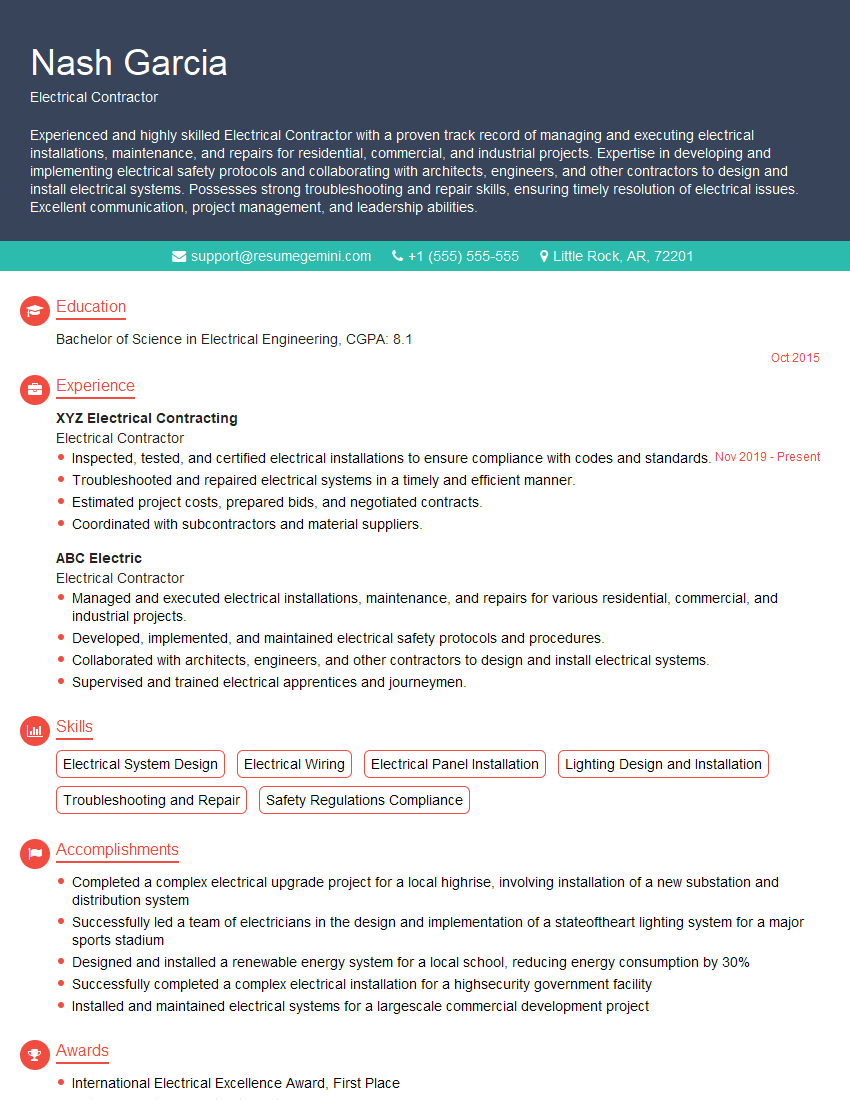
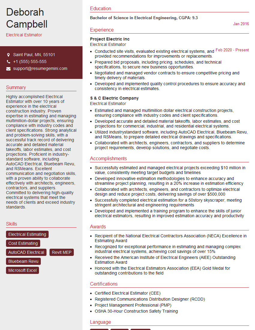
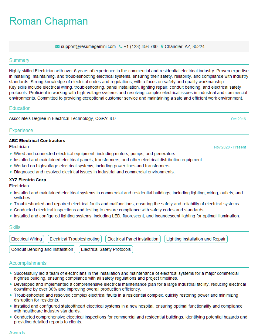
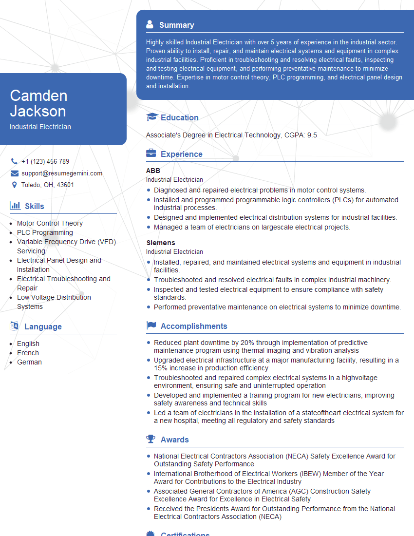
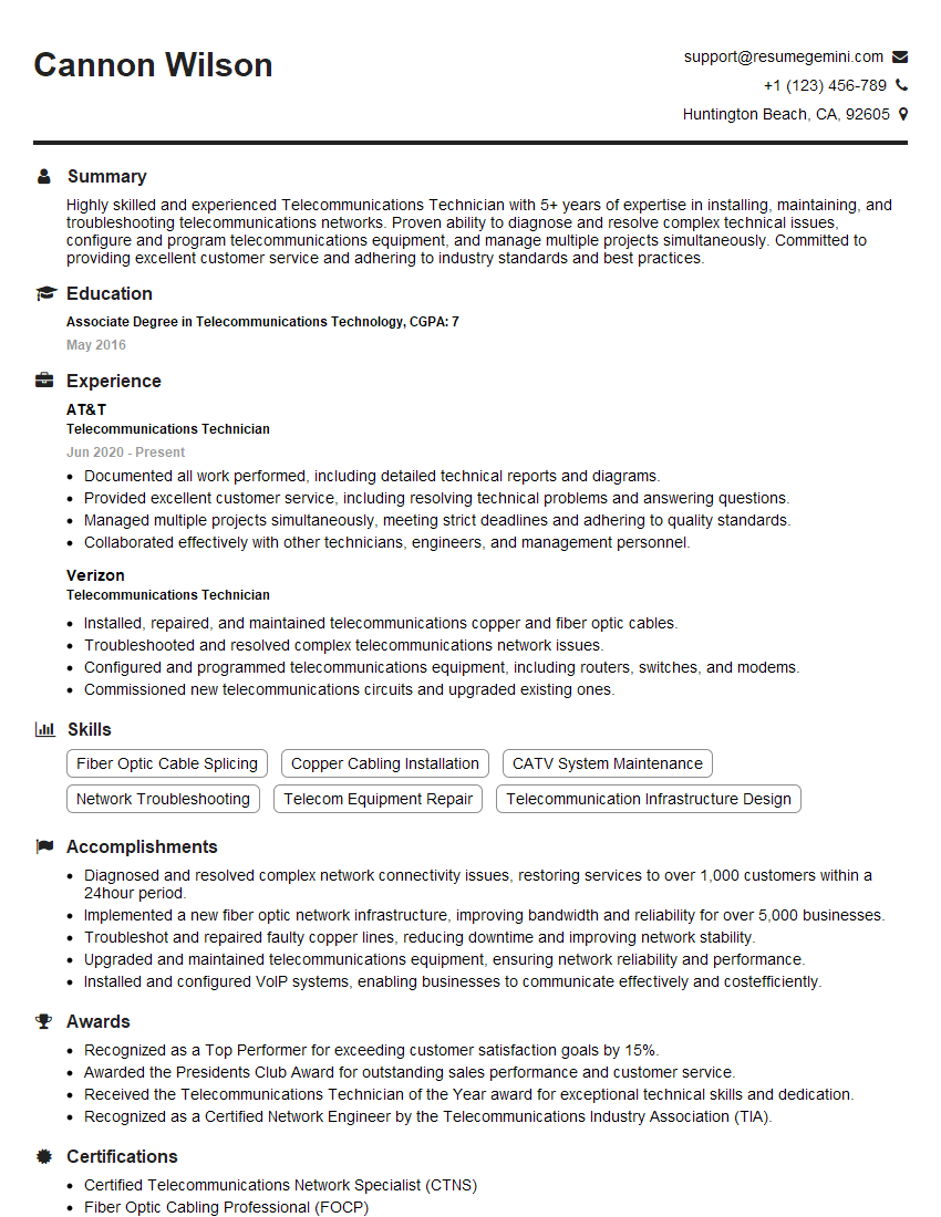
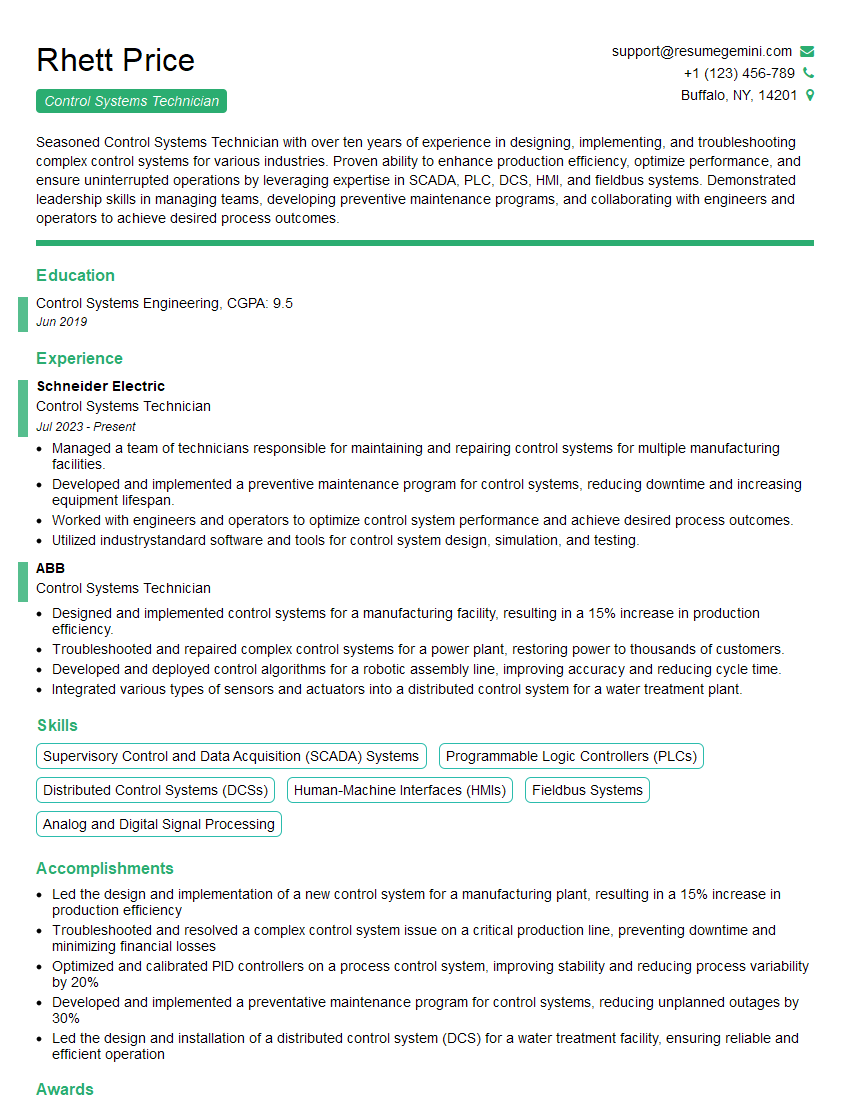
Mastering Electrical Wiring and Control opens doors to exciting career opportunities and significant professional growth. To maximize your chances, a strong resume is essential. Create an ATS-friendly resume that highlights your skills and experience effectively. ResumeGemini is a trusted resource that can help you build a professional resume that stands out. We offer examples of resumes tailored to Electrical Wiring and Control to guide you through the process. Take control of your future – start building your winning resume today!
Explore more articles
Users Rating of Our Blogs
Share Your Experience
We value your feedback! Please rate our content and share your thoughts (optional).
What Readers Say About Our Blog
Hello,
We found issues with your domain’s email setup that may be sending your messages to spam or blocking them completely. InboxShield Mini shows you how to fix it in minutes — no tech skills required.
Scan your domain now for details: https://inboxshield-mini.com/
— Adam @ InboxShield Mini
Reply STOP to unsubscribe
Hi, are you owner of interviewgemini.com? What if I told you I could help you find extra time in your schedule, reconnect with leads you didn’t even realize you missed, and bring in more “I want to work with you” conversations, without increasing your ad spend or hiring a full-time employee?
All with a flexible, budget-friendly service that could easily pay for itself. Sounds good?
Would it be nice to jump on a quick 10-minute call so I can show you exactly how we make this work?
Best,
Hapei
Marketing Director
Hey, I know you’re the owner of interviewgemini.com. I’ll be quick.
Fundraising for your business is tough and time-consuming. We make it easier by guaranteeing two private investor meetings each month, for six months. No demos, no pitch events – just direct introductions to active investors matched to your startup.
If youR17;re raising, this could help you build real momentum. Want me to send more info?
Hi, I represent an SEO company that specialises in getting you AI citations and higher rankings on Google. I’d like to offer you a 100% free SEO audit for your website. Would you be interested?
Hi, I represent an SEO company that specialises in getting you AI citations and higher rankings on Google. I’d like to offer you a 100% free SEO audit for your website. Would you be interested?
good
