The thought of an interview can be nerve-wracking, but the right preparation can make all the difference. Explore this comprehensive guide to Interpretation of Engineering Drawings and Specifications interview questions and gain the confidence you need to showcase your abilities and secure the role.
Questions Asked in Interpretation of Engineering Drawings and Specifications Interview
Q 1. Explain the difference between orthographic and isometric projections.
Orthographic and isometric projections are two different ways of representing a three-dimensional object on a two-dimensional drawing. Think of it like taking photos of a building from different angles. Orthographic projection uses multiple views (typically top, front, and side) to show the object’s dimensions accurately, as if looking at it straight-on from each direction. Each view shows only two dimensions at a time. Isometric projection, on the other hand, shows a single view that depicts all three dimensions simultaneously, offering a more pictorial representation. It’s like looking at a slightly angled perspective, allowing us to visualize the object’s overall form.
Orthographic Projection: Imagine drawing a cube. You’d have a top view showing the square top surface, a front view showing the square front surface, and a side view showing the square side surface. These three views, when combined, fully define the cube’s shape and dimensions. They’re accurate but lack a holistic visual representation.
Isometric Projection: In contrast, an isometric drawing of the same cube would show all three dimensions in a single sketch, albeit with slightly distorted angles. While not precisely to scale along each axis, it gives a quick visual understanding of the object’s form. It’s often used for quick sketches or illustrations in presentations.
Q 2. How do you identify different line types and their significance on an engineering drawing?
Line types in engineering drawings are crucial for conveying information about the object’s features and construction. Different lines represent different elements, enabling clear communication between designers, manufacturers, and builders.
- Object Lines (Solid Lines): These thick, solid lines define the visible edges and outlines of an object. They’re the most prominent lines on the drawing.
- Hidden Lines (Dashed Lines): These lines show edges or features that are hidden from the chosen viewing perspective. For example, a hole drilled through a block would have its inner edges represented by dashed lines in a view where the hole isn’t directly visible.
- Center Lines (Dashed-Dotted Lines): These lines indicate axes of symmetry, centers of holes, or the central axis of circular features. They’re typically thinner than object lines.
- Dimension Lines (Thin Solid Lines with Arrows): Used to indicate the size and location of object features, always ending with arrowheads.
- Leader Lines (Thin Solid Lines): These lines connect notes, symbols, or dimensions to specific features of the object.
- Section Lines (Thin Solid Lines): Used to indicate the cut-plane of a sectional view and often have a consistent pattern (like hatching).
Understanding line types is fundamental. Misinterpreting a dashed line as a solid line, for instance, can lead to manufacturing errors. Always refer to the drawing’s legend or standards if unsure.
Q 3. What are the common types of dimensioning used in engineering drawings?
Several dimensioning methods exist, each with specific applications. Choosing the right method is key for clear and accurate communication.
- Aligned Dimensioning: Dimension lines are parallel to each other, with dimension text placed above or below the line. This is a common method for linear dimensions.
- Unidirectional Dimensioning: All dimension text is oriented in the same direction (usually horizontally). This method is preferred when clarity is paramount, especially in complex drawings.
- Chain Dimensioning: Dimensions are placed consecutively along a common baseline. This method is efficient but can accumulate errors; hence, it’s used judiciously.
- Ordinate Dimensioning: Used to define the location of points relative to a common origin (usually the x-y coordinate system). This is prevalent in complex parts with many features.
- Radial Dimensioning: Specifies the radius or diameter of circular or arc features. It makes clear whether the measurement is from the center or circumference.
The choice of method influences both readability and potential for error. For instance, chain dimensioning can accumulate errors if a value changes, while ordinate dimensioning needs to have a clearly defined origin.
Q 4. Describe the importance of tolerances and how they are indicated on drawings.
Tolerances represent the permissible variation in a dimension or feature. They are critical because manufacturing processes are never perfectly precise. Tolerances ensure parts will function correctly even with minor variations.
Tolerances are indicated on drawings using various methods. A common way is to specify a plus/minus value after the nominal dimension. For example, ’10 ± 0.1 mm’ means the dimension can vary from 9.9 mm to 10.1 mm. Sometimes, a tolerance range is shown as ’10-10.2 mm’, indicating an allowable variation of 0.2 mm.
Geometric Dimensioning and Tolerancing (GD&T) is a more sophisticated system. It uses symbols and zones to define allowable variations in form, orientation, location, and runout. Understanding GD&T is essential for precision engineering, allowing for finer control and ensuring interchangeability of parts. A part might be dimensionally correct, but if it is slightly out of shape, GD&T helps clarify those aspects.
Q 5. Explain the role of a title block in an engineering drawing.
The title block is the rectangular area usually found in the bottom right corner of an engineering drawing. It contains critical information necessary to identify and understand the drawing. Think of it as the drawing’s ‘identity card’.
Key information within a title block typically includes:
- Drawing Number: A unique identifier for the drawing.
- Title or Description: A brief description of what the drawing represents.
- Revision Number: Indicates the revision level of the drawing.
- Date: The date the drawing was created or last revised.
- Scale: The scale used in the drawing (e.g., 1:10, 1:100).
- Company Name and/or Project Name: The company that produced the drawing and the project to which it pertains.
- Designer and Checker Names: Identifying those who created and reviewed the drawing.
A complete and accurate title block is vital for traceability, version control, and seamless collaboration within a project team. Missing or incorrect information could lead to serious misunderstandings.
Q 6. How do you interpret section views and detail views on a drawing?
Section views and detail views are used to reveal interior features or details that would otherwise be hidden in a standard view. They provide clarity and avoid clutter in the main drawing.
Section Views: These views show an imaginary cut-through the object, revealing its internal structure. A cut-plane line on the main drawing indicates where the section view is taken. Hatching is often used to differentiate the sectioned area from the rest of the object.
Detail Views: These views show enlarged or more detailed views of specific features. They’re usually used for components that are complex or require precise dimensions. A leader line often connects the detail view to its location on the main drawing.
For example, imagine a complex mechanical assembly. A section view can reveal the arrangement of internal components, while detail views might show the precise dimensions and tolerances of a specific gear or bearing. Combining both views provides a comprehensive understanding of the assembly, far exceeding the capacity of one overall view.
Q 7. What are common symbols used to represent materials on engineering drawings?
Engineering drawings use various symbols to represent materials concisely. These symbols are standardized to prevent confusion. The specific standard used (like ASME Y14.5 in the US or ISO standards internationally) will determine the precise symbol used.
Common material symbols can include:
- Steel: Often represented by a hatched pattern or specific letters such as ‘ST’ or a material grade code.
- Aluminum: May be indicated by a specific symbol or material grade abbreviation.
- Cast Iron: Often shown with a particular pattern of dots or dashes.
- Plastics: May use a unique symbol, material type code (like ABS, PP, etc.), or other identification methods.
- Wood: Typically represented by a specific pattern or wood type description.
Material identification is crucial for manufacturing. The wrong material could lead to a faulty or unsafe product. Always refer to the material specification table or legend on the drawing to confirm the material intended for each part.
Q 8. Explain the process of interpreting a bill of materials (BOM).
A Bill of Materials (BOM) is a comprehensive list of all the components, materials, and parts required to manufacture a product. Interpreting a BOM involves understanding its structure and extracting crucial information. It’s like a recipe for a product, detailing every ingredient needed.
The process typically involves:
- Identifying the Product: The BOM should clearly state the product it pertains to.
- Understanding the Structure: BOMs are often organized in a tabular format with columns representing part number, description, quantity, material, and potentially other relevant details. Familiarizing yourself with this structure is key.
- Deciphering Part Numbers: Part numbers are crucial for sourcing and ordering. They often follow a specific naming convention within a company, providing clues about the part’s function or characteristics. Sometimes you need a separate parts list to help decode them.
- Checking Quantities: Accurate quantities are vital to prevent shortages or overstocking. Look out for revisions or notes affecting the quantities.
- Understanding Materials: This involves interpreting material specifications (e.g., grade of steel, type of plastic). This helps to ensure the right materials are used for the right application.
- Identifying Dependencies: Some BOMs highlight the hierarchical relationships between parts – showing sub-assemblies.
Example: A BOM for a simple chair might include entries for legs (4x), seat (1x), backrest (1x), screws (16x), and finish (1x). Analyzing this indicates that four legs are needed for each chair, and the material and finish are crucial aspects.
Q 9. How do you identify revisions and updates on engineering drawings?
Revisions and updates on engineering drawings are crucial for keeping the design current and accurate. They’re usually indicated using a revision block or a revision table, often found in a corner of the drawing.
These blocks typically show:
- Revision Letter/Number: Each revision is assigned a letter (A, B, C…) or a number (1, 2, 3…).
- Revision Date: The date the revision was implemented.
- Description of Changes: A brief description of the changes made in that revision (e.g., ‘Corrected dimension on part A’, ‘Added new component X’).
Sometimes, changes are highlighted directly on the drawing using symbols, like circles or clouds, referencing the revision table for details. It’s critical to always refer to the latest revision to ensure you’re working with the most up-to-date information. Ignoring revisions could lead to building incorrect products or components.
Example: Revision ‘B’ might indicate a change in the diameter of a hole, while revision ‘C’ might add a note regarding the material specification. You would ignore Revision A data if you are working with Revision C.
Q 10. What is the purpose of a welding symbol?
Welding symbols are a standardized way to communicate complex welding instructions concisely on engineering drawings. They provide all necessary information about a weld in a single, compact symbol, avoiding lengthy written descriptions.
A welding symbol typically includes:
- Reference Line: The horizontal line connecting the symbol elements.
- Arrow Side: Indicates the side of the joint where the symbol applies.
- Basic Weld Symbol: Represents the type of weld (e.g., fillet, groove, spot).
- Dimensions: Size, length, etc., of the weld.
- Process Specification: Specifies the welding process to be used.
- Other Specifications: Additional specifications (e.g., surface finish requirements, weld penetration depth).
Think of it as a shorthand for the welder. Each element provides the welder with the specifics required to produce the weld correctly and efficiently. Misinterpretation can lead to safety hazards and faulty welds.
Example: A symbol might indicate a 6mm fillet weld on the arrow side, using the Gas Metal Arc Welding (GMAW) process. The absence of symbols on the opposite side implies no welding is required there.
Q 11. Describe your experience reading and interpreting electrical schematics.
I have extensive experience in reading and interpreting electrical schematics, gained from [mention specific projects or roles]. Understanding schematics is essential for troubleshooting, design, and maintenance of electrical systems. It’s like reading a map of the electrical flow.
My skills include:
- Identifying Components: I can readily identify symbols for various electrical components (resistors, capacitors, transistors, integrated circuits, etc.).
- Tracing Signal Paths: I can efficiently trace signal paths and power flows through the circuit.
- Understanding Logic Gates: I’m proficient in understanding logic gates and Boolean algebra used in digital circuits.
- Interpreting Component Values: I accurately interpret values like resistance, capacitance, and voltage ratings.
- Identifying Wiring Diagrams: I differentiate between single-line diagrams and detailed wiring diagrams.
Example: In a recent project involving a PLC system, I used the electrical schematic to identify a faulty relay that was causing a machine malfunction. By tracing the signal paths, I quickly pinpointed the issue and resolved it.
Q 12. How familiar are you with different CAD software packages (AutoCAD, SolidWorks, etc.)?
I am proficient in several CAD software packages, including AutoCAD, SolidWorks, and [mention any others, e.g., Revit, Inventor]. My experience spans [mention years of experience] and includes both 2D and 3D modeling, drafting, and design.
My skills in these packages include:
- 2D Drafting: Creating and editing detailed technical drawings, including dimensioning and annotation.
- 3D Modeling: Developing 3D models of components and assemblies, performing analysis, and generating manufacturing-ready drawings.
- Data Management: Managing project files, layers, and revisions effectively.
- Collaboration: Working collaboratively on projects using cloud-based platforms.
I am confident in using these tools to generate, interpret, and modify engineering drawings. Proficiency in CAD software is vital for creating and understanding modern engineering designs.
Q 13. Explain how you would handle discrepancies or errors found in engineering drawings.
Discovering discrepancies or errors in engineering drawings is a serious matter requiring careful handling. Ignoring them can have significant consequences.
My approach involves:
- Verification: I first verify the discrepancy. Is it a real error or a misunderstanding on my part? Sometimes a second review clarifies things.
- Documentation: I meticulously document the discrepancy, including its location on the drawing, the nature of the error, and any supporting evidence. Photos and detailed notes are essential.
- Communication: I communicate the discrepancy to the relevant stakeholders (design engineers, project managers, etc.). Clear, concise communication prevents misinterpretations and delays.
- Resolution: I actively participate in resolving the issue. This may involve reviewing previous revisions, contacting the designer, or suggesting solutions. Following established change management procedures is important.
- Revision Control: Once resolved, I ensure the drawing is updated according to the established revision control system, with a clear description of the corrections.
It’s critical to use a methodical approach to ensure that errors are identified, resolved correctly, and properly documented to prevent repetition.
Q 14. Describe a time you had to interpret a complex engineering drawing.
During my time at [previous company name], I encountered a complex assembly drawing for a specialized robotic arm. The drawing was highly detailed, containing numerous components, intricate wiring diagrams, and complex pneumatic systems. It was a true challenge.
My approach to interpreting this drawing was:
- Systematic Breakdown: I started by breaking down the assembly into its sub-assemblies. This helped to simplify the overall complexity.
- Reference Materials: I utilized supplementary documents such as part lists, component specifications, and pneumatic schematics to understand the functionality of each part.
- 3D Modeling: I used SolidWorks to create a 3D model based on the 2D drawing. This significantly improved my understanding of the spatial relationships between different components.
- Team Collaboration: I collaborated with senior engineers to clarify ambiguous parts of the drawing. Open communication was vital in navigating this complex design.
Through this methodical process, I successfully interpreted the drawing, contributing significantly to the successful assembly and testing of the robotic arm. This experience highlighted the value of breaking down complex challenges into smaller, manageable tasks, and the power of team collaboration.
Q 15. How do you ensure you are interpreting drawings accurately?
Accurate interpretation of engineering drawings hinges on a methodical approach. It’s not just about seeing lines and numbers; it’s about understanding the design intent. I begin by thoroughly reviewing the title block, which provides crucial information like the drawing number, revision level, scale, and relevant standards. Then, I systematically examine each view, section, and detail, carefully noting dimensions, tolerances, and annotations. Cross-referencing with other related drawings and specifications is vital. I constantly ask myself, ‘What is this part’s function? How does it interact with other components?’ This helps me validate my interpretation against the overall design goals. Finally, I always perform a sanity check—do the dimensions and tolerances make sense in the context of the part’s functionality and manufacturability? For instance, if a dimension seems unusually tight, I’d investigate further to confirm its correctness and potential implications for manufacturing.
For example, I once discovered a critical oversight in a drawing where a critical dimension was missing. By systematically reviewing related drawings and consulting the specification document, I was able to identify the correct value, preventing a costly manufacturing error.
Career Expert Tips:
- Ace those interviews! Prepare effectively by reviewing the Top 50 Most Common Interview Questions on ResumeGemini.
- Navigate your job search with confidence! Explore a wide range of Career Tips on ResumeGemini. Learn about common challenges and recommendations to overcome them.
- Craft the perfect resume! Master the Art of Resume Writing with ResumeGemini’s guide. Showcase your unique qualifications and achievements effectively.
- Don’t miss out on holiday savings! Build your dream resume with ResumeGemini’s ATS optimized templates.
Q 16. What are your strategies for understanding unclear or ambiguous drawings?
Encountering unclear or ambiguous drawings is unfortunately common. My strategies involve a multi-pronged approach. First, I meticulously examine all available documentation, including revision history, notes, and any accompanying specifications. Sometimes, seemingly insignificant notes or symbols hold the key to understanding the ambiguity. Second, I leverage my experience and knowledge of manufacturing processes and common design practices to infer the intended meaning. Third, I don’t hesitate to seek clarification from the design engineer or other relevant stakeholders. Open communication is crucial in resolving ambiguities and ensuring that everyone is on the same page. Sometimes, a simple conversation can save hours of speculation and potential errors. Lastly, I document all assumptions and interpretations made during the clarification process, ensuring that my understanding is clearly recorded and auditable.
Imagine an assembly drawing where the connection between two parts is unclear. I wouldn’t just guess; I’d review related parts lists, check for notes or callouts, and if necessary, contact the designer to confirm the intended assembly method. Clear documentation of these steps is vital for transparency and error prevention.
Q 17. Explain your understanding of Geometric Dimensioning and Tolerancing (GD&T).
Geometric Dimensioning and Tolerancing (GD&T) is a symbolic language used on engineering drawings to define precisely the size, form, orientation, location, and runout of features. It’s far more precise than traditional dimensioning methods, minimizing ambiguity and ensuring interchangeability of parts. GD&T uses symbols and zones to specify tolerance limits, allowing manufacturers to create parts that meet specific functional requirements. Understanding GD&T requires knowledge of the various symbols (like position, perpendicularity, flatness), their associated tolerances, and how they work together to define acceptable variations in manufactured parts. This ensures that parts fit together correctly and function as intended.
For example, a Σ symbol indicates position tolerance, specifying how much variation is permissible in the location of a hole. This is far more informative than simply specifying a nominal diameter and relying on general tolerances, which could lead to unacceptable variations in assembly.
Q 18. How do you interpret assembly drawings?
Interpreting assembly drawings requires a systematic approach that goes beyond simply understanding individual components. It involves visualizing the entire assembly process. I start by analyzing the exploded view (if provided), which shows the individual components and their relative positions. Then, I carefully examine the detailed views of individual parts and their mating relationships. I pay close attention to the assembly sequence, identifying any specific instructions or notes regarding the order of assembly. Furthermore, I consider factors such as fasteners, clearances, and potential interference between parts. I often create a mental (or physical) model of the assembly to verify that the components fit together correctly and function as intended. Using software like CAD can be very helpful in this process, allowing for the manipulation and inspection of the assembly model.
For example, when working with a complex mechanism, I would pay particular attention to the sequence of assembly, ensuring that parts are inserted correctly and that no components interfere with each other. Visualizing the assembly in 3D helps confirm that the design is feasible and avoids potential assembly conflicts.
Q 19. How familiar are you with different material specifications?
Familiarity with material specifications is essential for interpreting engineering drawings accurately. I am proficient in understanding various material designations, including those specified by ASTM (American Society for Testing and Materials), ASME (American Society of Mechanical Engineers), and ISO (International Organization for Standardization). This includes understanding material properties such as tensile strength, yield strength, hardness, ductility, and weldability. Recognizing the limitations of different materials is critical in assessing the feasibility and functionality of a design. I also understand the significance of material selection for specific applications, taking into account factors such as cost, weight, corrosion resistance, and environmental impact. The material specification isn’t just a set of letters and numbers; it’s a critical piece of information that dictates the part’s performance characteristics.
For example, specifying ‘AISI 304 stainless steel’ tells me about the material’s corrosion resistance, strength, and machinability—all crucial factors for determining the part’s suitability for the intended application.
Q 20. How do you utilize engineering specifications alongside drawings?
Engineering specifications and drawings work in tandem. Drawings provide the geometrical representation of a part or assembly, while specifications provide the detailed non-graphical requirements. The specifications may define material properties, surface finishes, tolerances that are not depicted graphically in the drawing, manufacturing processes, quality control procedures, and other critical parameters. I always interpret drawings in conjunction with the relevant specifications, ensuring that all requirements are met. Any discrepancies between the drawing and the specification must be resolved before proceeding. This collaborative interpretation ensures a complete and accurate understanding of the design requirements.
A good analogy would be a recipe and a diagram of a cake: the drawing is like the diagram, showing you the shape and layering; the specification is the recipe, providing the ingredients, quantities, and baking instructions. Only when both are used together can you create a successful cake (or a functional engineering component).
Q 21. Describe your understanding of different drawing scales.
Drawing scales represent the ratio between the dimensions on the drawing and the actual dimensions of the object. Understanding different scales is vital for accurate interpretation. Common scales include 1:1 (full size), 1:2 (half size), 2:1 (double size), and others. I am familiar with various scale notations and can accurately convert measurements from the drawing to real-world dimensions. The scale is always clearly indicated in the drawing’s title block. Misunderstanding the scale can lead to significant errors in manufacturing or construction. Furthermore, I understand the implications of different scales for accuracy and detail. Larger scales allow for more detailed representation, while smaller scales provide an overview of a larger assembly or system. Choosing the appropriate scale is crucial in conveying the necessary information effectively.
For example, a 1:100 scale drawing means that 1 unit on the drawing represents 100 units in reality. If a dimension on the drawing measures 5cm, the actual dimension would be 500cm or 5 meters.
Q 22. Explain the importance of proper drawing documentation and management.
Proper drawing documentation and management are paramount for successful engineering projects. Think of drawings as the blueprints of a project – they communicate the design intent, manufacturing specifications, and assembly instructions. Without meticulous documentation, projects risk errors, delays, and cost overruns.
- Preventing Errors: Clear, concise drawings minimize misinterpretations, leading to fewer mistakes during construction or manufacturing.
- Facilitating Collaboration: Well-organized drawings enable seamless collaboration among engineers, designers, contractors, and manufacturers. Everyone works from the same source of truth.
- Managing Revisions: A robust system for managing revisions ensures everyone uses the latest version, preventing costly rework from outdated documents.
- Legal Compliance: Comprehensive documentation can be crucial in resolving disputes or proving compliance with regulations.
- Long-term Maintainability: Accurate records enable easy maintenance and repair long after the project’s completion. Imagine trying to repair a machine without its original schematics!
For example, in a recent project involving a complex piece of machinery, meticulously documented drawings allowed us to identify and correct a design flaw early in the process, avoiding substantial rework and cost overruns.
Q 23. How do you ensure drawings comply with relevant standards (e.g., ASME, ISO)?
Adherence to relevant standards is non-negotiable for engineering drawings. Standards like ASME (American Society of Mechanical Engineers) and ISO (International Organization for Standardization) provide a common language and ensure drawings meet safety, performance, and quality requirements. We ensure compliance through a multi-step process:
- Standard Selection: Identifying the applicable standards based on the project’s scope, industry, and geographical location.
- Template Usage: Using drawing templates pre-formatted to comply with chosen standards. This automatically incorporates elements like title blocks, revision tables, and specific drawing notations.
- Software Tools: Utilizing CAD software with built-in features for standards compliance, such as automated dimensioning and tolerance checks.
- Peer Review: Conducting thorough peer reviews to check for inconsistencies and deviations from the selected standard. A second pair of eyes catches many errors.
- Formal Verification: In some cases, engaging external certification bodies to independently verify compliance, particularly for critical projects.
For instance, when working on pressure vessels, we strictly adhere to ASME Section VIII, Division 1, ensuring all aspects meet safety and design standards. Any deviation is carefully documented and justified.
Q 24. Describe your experience working with different drawing formats (PDF, DWG, etc.).
My experience spans a wide range of drawing formats, including PDF, DWG (AutoCAD), DXF, and more recently, IFC (Industry Foundation Classes) for Building Information Modeling (BIM) projects. Each format has its strengths and weaknesses.
- DWG/DXF: Native formats for CAD software, allowing for full editing and modification. Ideal for collaborative design and revision control.
- PDF: Excellent for distribution and archiving; however, it’s read-only, limiting editing capabilities. Useful for sharing final approved designs.
- IFC: A crucial format for integrating various disciplines in BIM projects. It allows different software applications to exchange data seamlessly.
In a past project, we used DWG for design and collaboration, then exported to PDF for client review and archiving, maintaining a well-defined workflow and leveraging each format’s strengths.
Q 25. How do you communicate complex technical information from drawings to non-technical audiences?
Communicating complex technical information from drawings to non-technical audiences requires a clear and concise approach. Technical jargon needs to be avoided, replaced with simpler terms and visuals.
- Simplified Diagrams: Creating simplified diagrams or flowcharts that highlight key components and their interactions.
- Visual Aids: Using photos, videos, and 3D models to illustrate complex concepts.
- Analogies: Employing relatable analogies to explain technical functions. For example, explaining a circuit’s function by comparing it to a water pipe system.
- Layman’s Terms: Avoiding technical terminology, using plain language and simple sentence structure.
- Interactive Presentations: Developing interactive presentations or demonstrations to engage the audience and allow for questions.
For example, when presenting a complex design to a client with limited engineering knowledge, I utilized a 3D model and simple animations to explain the function, operation and safety aspects of the design.
Q 26. How do you use engineering drawings to troubleshoot technical issues?
Engineering drawings are invaluable tools for troubleshooting. They serve as a detailed roadmap of the system, pinpointing components and their relationships.
- Component Identification: Identifying the faulty component using the drawing’s designations and bill of materials.
- Assembly Analysis: Analyzing the assembly sequence to determine how the component interacts with others.
- Dimensional Verification: Checking dimensions and tolerances to identify any deviations from specifications.
- Failure Analysis: Using the drawing to identify potential points of failure and investigate the root cause.
- Modification Planning: Designing modifications or repairs with the aid of the drawing.
In a recent scenario, a malfunctioning pump was successfully diagnosed using its detailed assembly drawing. A misaligned component revealed in the drawing was pinpointed as the cause of the problem, facilitating efficient repair.
Q 27. Explain your process for verifying the completeness and accuracy of a set of drawings.
Verifying drawing completeness and accuracy is a critical step. This is done through a rigorous checklist-based approach.
- Title Block Verification: Checking that all information in the title block (revision, date, designer, etc.) is accurate and complete.
- Dimension and Tolerance Check: Verifying all dimensions, tolerances, and annotations are clearly indicated and consistent.
- Material Specifications: Confirming that all materials and finishes are correctly specified.
- Cross-referencing: Ensuring that all referenced drawings and documents are consistent and accurate.
- Geometric Dimensioning and Tolerancing (GD&T): Properly interpreting and applying GD&T symbols and specifications (if present).
- Peer Review: Utilizing a peer review process to catch potential oversights or errors.
I often use a formal checklist and a detailed review matrix to document every step of the verification process. This ensures consistency and thoroughness, leaving no stone unturned.
Q 28. Describe your experience with 3D modeling software and its role in interpreting engineering drawings.
3D modeling software, such as SolidWorks or AutoCAD Inventor, plays a vital role in interpreting engineering drawings. It bridges the gap between 2D representations and a three-dimensional understanding.
- Visualization: 3D models offer a clearer, more intuitive visualization of the designed object, facilitating better comprehension.
- Clash Detection: Identifying potential clashes or interferences between components early in the design process, saving time and resources.
- Detailed Analysis: Performing simulations and analyses such as Finite Element Analysis (FEA) to validate the design.
- Enhanced Communication: Creating realistic renderings or animations for more effective communication with clients and stakeholders.
- Reverse Engineering: In some cases, 3D scanning and modeling can be used to create digital models from existing physical parts, useful for repairs or modifications.
In a past project, we used 3D modeling to identify a potential interference between two components that wasn’t apparent from the 2D drawings alone. This prevented a costly assembly problem later on.
Key Topics to Learn for Interpretation of Engineering Drawings and Specifications Interview
- Drawing Types and Standards: Understanding different drawing types (e.g., orthographic, isometric, sectional) and relevant industry standards (e.g., ASME, ISO).
- Dimensioning and Tolerancing: Interpreting dimensions, tolerances, and geometric dimensioning and tolerancing (GD&T) symbols to ensure accurate part manufacturing.
- Material Specifications: Identifying and understanding material properties and specifications as indicated on drawings and in accompanying documents.
- Bill of Materials (BOM) Interpretation: Analyzing BOMs to understand the components required for assembly and manufacturing.
- Blueprint Reading Techniques: Developing proficiency in effectively reading and interpreting detailed engineering blueprints, including understanding views, sections, and details.
- Practical Application: Relating theoretical knowledge to real-world scenarios, such as identifying potential design flaws or manufacturing challenges based on drawing interpretation.
- Problem-Solving: Demonstrating the ability to analyze complex drawings, identify inconsistencies, and propose solutions to design or manufacturing issues.
- Technical Specifications: Understanding and interpreting detailed technical specifications accompanying engineering drawings.
- Common Symbols and Abbreviations: Familiarity with standard symbols, abbreviations, and notations used in engineering drawings.
- Software Proficiency (if applicable): Demonstrating experience with CAD software (e.g., AutoCAD, SolidWorks) used for viewing and manipulating engineering drawings.
Next Steps
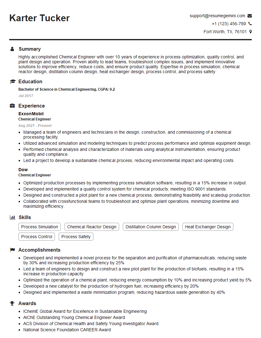
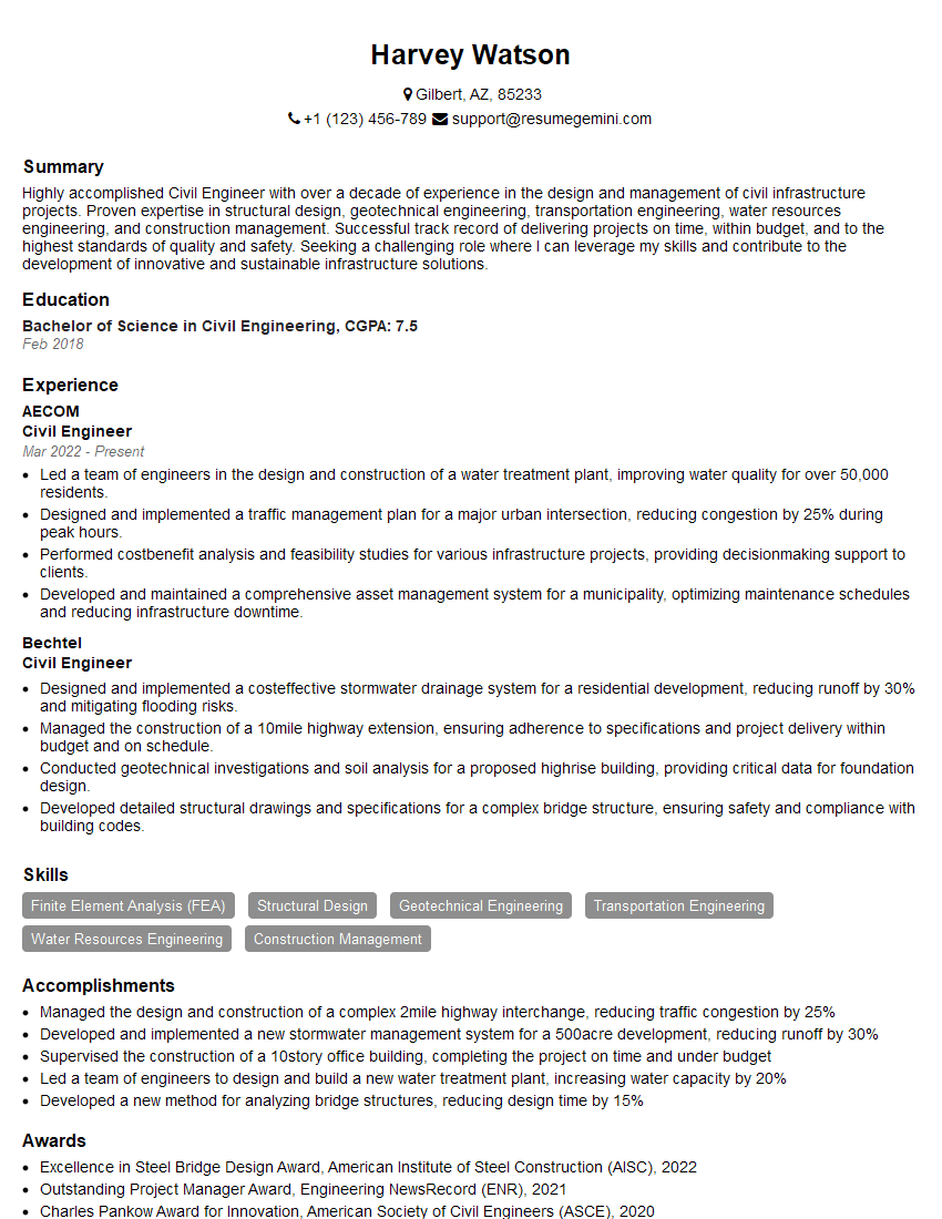
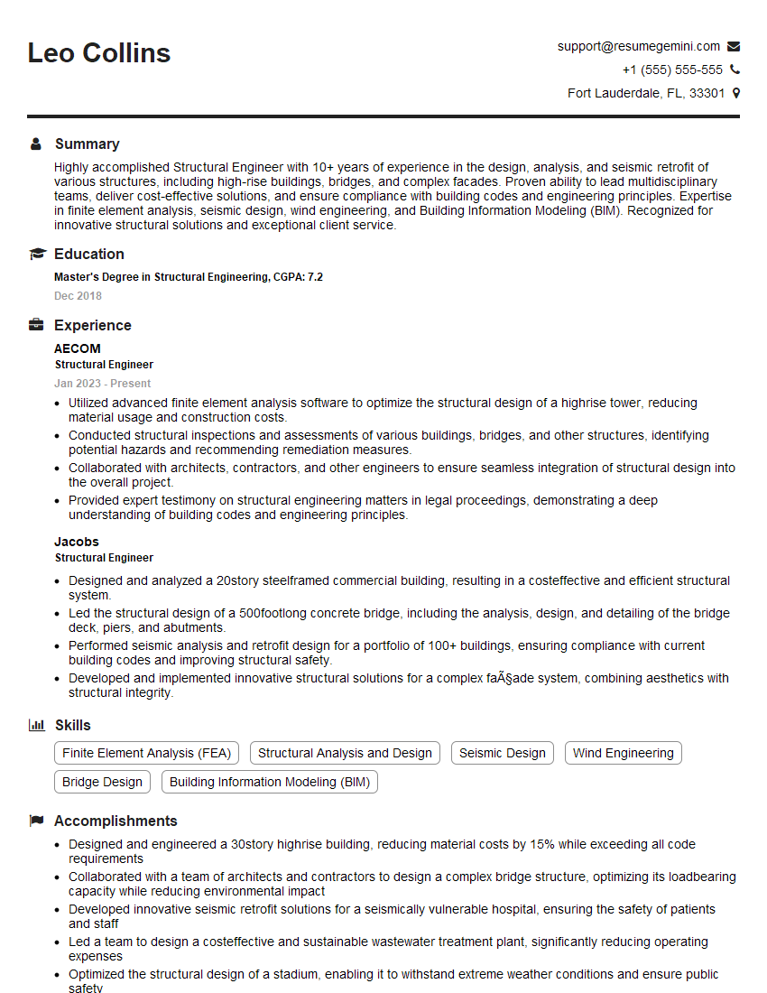
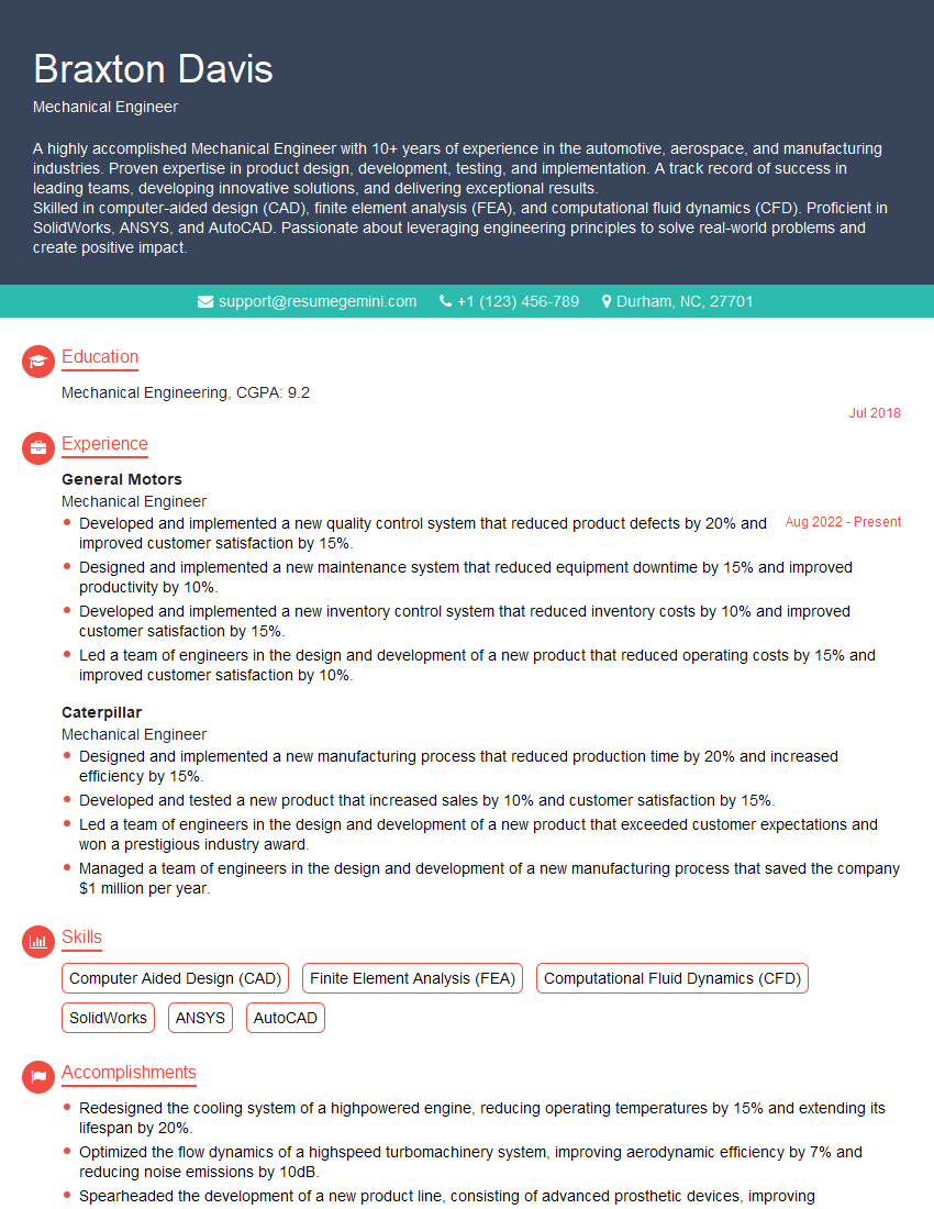
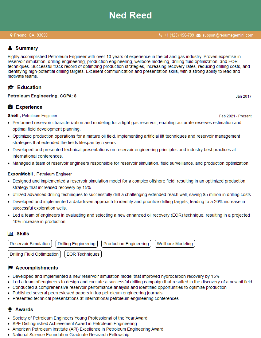
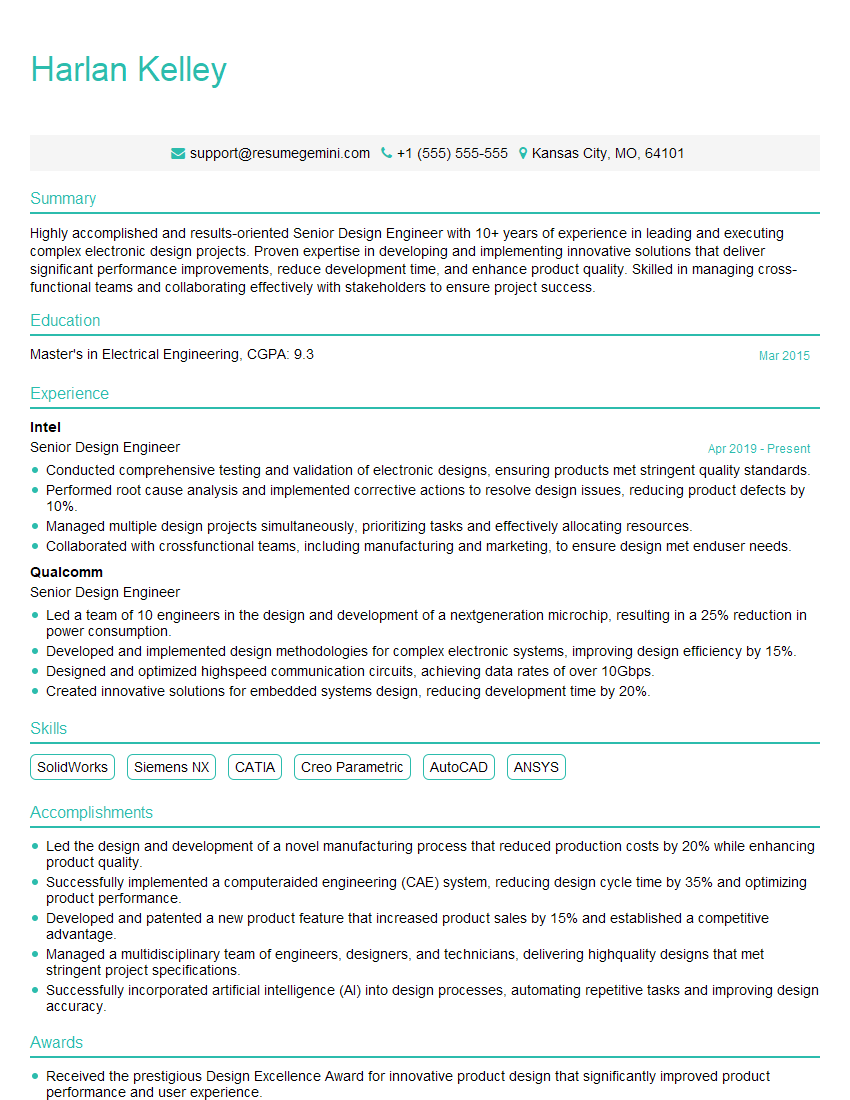
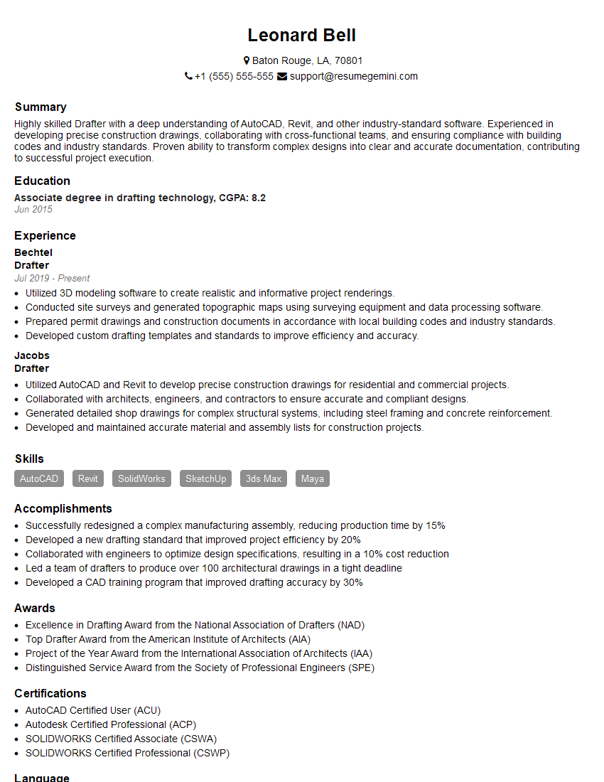
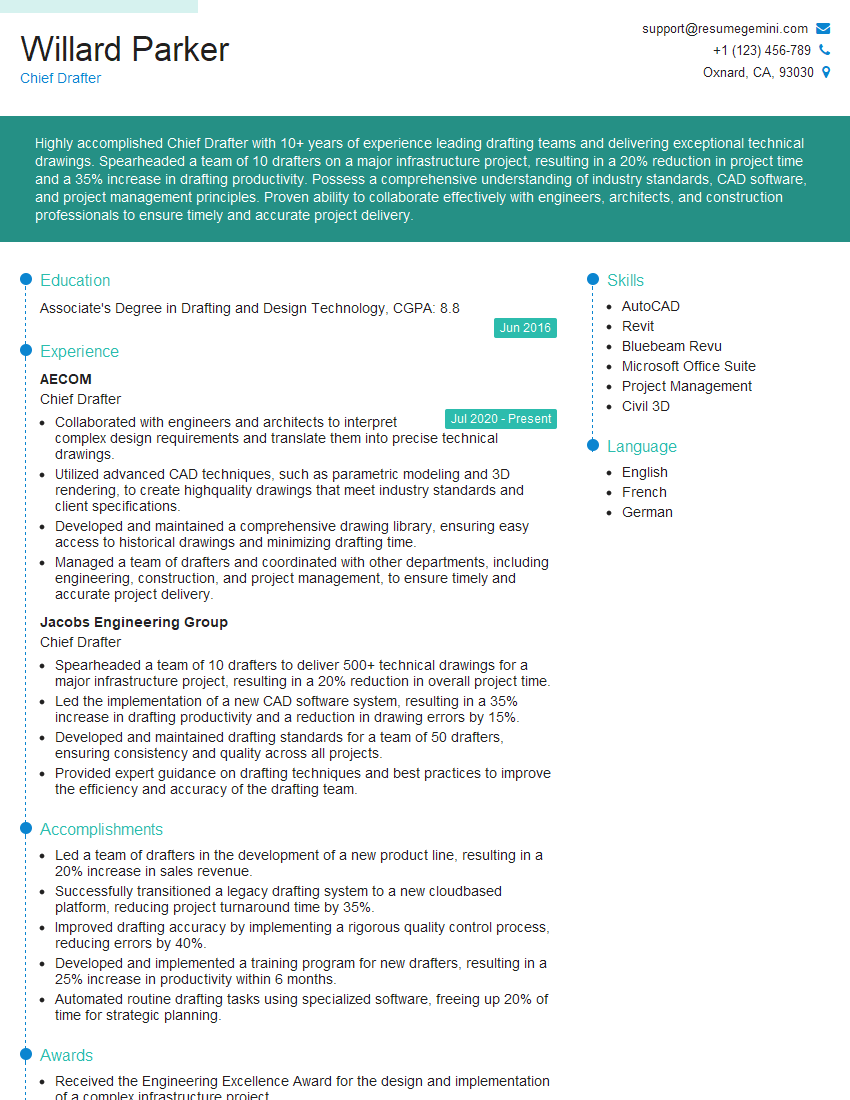
Mastering the interpretation of engineering drawings and specifications is crucial for career advancement in engineering and related fields. It demonstrates a crucial skill set for successful project execution and collaboration. To significantly improve your job prospects, invest time in crafting an ATS-friendly resume that highlights your abilities effectively. ResumeGemini is a trusted resource that can help you build a professional and impactful resume. Examples of resumes tailored to showcasing expertise in Interpretation of Engineering Drawings and Specifications are available through ResumeGemini to help guide you.
Explore more articles
Users Rating of Our Blogs
Share Your Experience
We value your feedback! Please rate our content and share your thoughts (optional).
What Readers Say About Our Blog
good
