The right preparation can turn an interview into an opportunity to showcase your expertise. This guide to Interpretation of Technical Drawings interview questions is your ultimate resource, providing key insights and tips to help you ace your responses and stand out as a top candidate.
Questions Asked in Interpretation of Technical Drawings Interview
Q 1. Explain the difference between orthographic and isometric projections.
Orthographic and isometric projections are two different ways of representing a three-dimensional object on a two-dimensional surface like a piece of paper. Think of it like taking photographs of an object from different angles.
Orthographic projection uses multiple views (typically top, front, and side) to show the object’s dimensions precisely. Each view shows only two dimensions of the object, and the views are related to each other using projection lines. Imagine taking separate photos of the front, side and top of a box. This is essentially what orthographic drawings do – they depict the object as seen directly from a certain perspective (front, top, side, etc.). The advantage is clarity and precision; all dimensions are explicitly shown.
Isometric projection, on the other hand, shows a single view of the object in three dimensions simultaneously. Imagine viewing a transparent box slightly from above. You can see some sides more fully than others. This is the core concept of an isometric drawing. It’s a pictorial representation, allowing for a quick visual understanding of the object’s overall shape and spatial relationships. However, the angles and dimensions aren’t shown directly and accurately, and require some understanding of the isometric grid.
In short: Orthographic drawings are precise and detailed, ideal for manufacturing, while isometric drawings are quick visual aids for design and presentation, suitable for quickly understanding the 3D arrangement.
Q 2. How do you interpret dimensioning and tolerances on a technical drawing?
Dimensioning and tolerances are crucial for manufacturing accuracy. Dimensioning specifies the size and location of features on a drawing. This includes lengths, widths, heights, diameters, and angles. These are usually shown with lines, arrowheads, and numbers indicating the exact measurement. For example, 10.00 ± 0.05 means a dimension of 10.00 units with a tolerance of ±0.05 units; meaning, any dimension between 9.95 and 10.05 would be acceptable.
Tolerances define the permissible variation in dimensions. It’s the acceptable range of deviation from the nominal dimension. Tolerances ensure that parts manufactured from the same drawing will fit together correctly. There are several ways to specify tolerances: using plus/minus values (as shown above), using limits (e.g., 10.00 – 10.05), or referencing a standardized tolerance system (like ISO 286).
Interpreting dimensioning and tolerances requires careful attention to detail and understanding of the symbols used. For example, a diameter is represented by a symbol Ø before the dimension, while radius is denoted by R. Understanding these notations is critical to accurately represent or interpret the intended dimensions.
Example: A shaft dimensioned as Ø25.00 ± 0.02 indicates a shaft with a nominal diameter of 25.00 units. The acceptable diameter range is between 24.98 and 25.02 units. Anything outside this range would be considered out of tolerance.
Q 3. Describe your experience with different types of technical drawings (e.g., assembly, detail, schematic).
Throughout my career, I’ve worked extensively with various types of technical drawings:
- Assembly Drawings: These show how multiple parts fit together to form a complete assembly. I’ve used these extensively to understand the relationship between components and the overall functioning of complex machinery and products. A classic example would be an assembly drawing of a bicycle, showing how the frame, wheels, handlebars, etc., interact and are assembled.
- Detail Drawings: These provide detailed information about individual parts, showing all dimensions, tolerances, materials, and manufacturing processes. Detail drawings are essential for manufacturing individual components. I’ve created and reviewed these to ensure accuracy and manufacturability of parts.
- Schematic Drawings: These diagrams are usually used in electrical or electronic engineering; showing the interconnection of components using symbols rather than geometric representations. I have experience interpreting electrical schematics to understand the flow of signals and power through a circuit. This is different from using mechanical detail drawings and requires a different set of skills.
My experience extends to interpreting and creating drawings for various industries, including automotive, manufacturing, and aerospace. I understand the specific standards and conventions that apply to each type.
Q 4. What software are you proficient in for viewing and interpreting technical drawings?
My expertise encompasses several software packages crucial for viewing and interpreting technical drawings. I am highly proficient in:
- AutoCAD: This is an industry-standard software for 2D and 3D drafting. I’m comfortable navigating drawings, measuring dimensions, and understanding the layer structure. My experience also includes modifying drawings for revisions when necessary, following a change request.
- SolidWorks: I can use this 3D modeling software to review complex models and generate various 2D views, allowing a better overall understanding of the three dimensional structure.
- Creo Parametric: Similar to SolidWorks, I utilize this software for 3D model review and creation of orthographic projections.
- Adobe Acrobat: This is essential for reviewing PDF versions of drawings, marking up changes, and adding comments during collaboration sessions.
I also possess the ability to navigate and interpret drawings from various less common or older formats, adapting my workflow to different file types efficiently.
Q 5. How do you identify and interpret symbols and abbreviations used in technical drawings?
Identifying and interpreting symbols and abbreviations in technical drawings relies heavily on familiarity with industry standards and conventions. There are several key strategies I use:
- Reference Documents: I always begin by checking for any accompanying documentation that provides a legend or key explaining the symbols and abbreviations used. This could be part of the drawing itself, or a separate document.
- Industry Standards: I have a strong understanding of relevant industry standards, such as ANSI, ISO, and ASME standards. These standards define common symbols and abbreviations. For example, the symbol
Ralmost universally denotes a radius, andØdenotes a diameter. - Contextual Understanding: If a symbol is unfamiliar, I assess its context within the drawing. Often, the surrounding dimensions or annotations give clues to its meaning. For example if you see a symbol in proximity to a circle, and you are viewing a machine part, you can very confidently assume it has to do with the circle’s dimensions such as its radius or diameter.
- Cross-referencing: If uncertainties remain, I cross-reference the drawing with related documents or consult with other engineers or design team members to clarify ambiguities.
My extensive experience has provided a rich knowledge base of common and specialized symbols and abbreviations across different disciplines.
Q 6. Explain your process for verifying the accuracy and completeness of a technical drawing.
Verifying the accuracy and completeness of a technical drawing is crucial to prevent errors in manufacturing and assembly. My process involves the following steps:
- Dimensional Check: I carefully check all dimensions for consistency and completeness. I verify that all necessary dimensions are present and that there are no conflicting dimensions.
- Geometric Tolerance Verification: I check that all geometric tolerances (e.g., perpendicularity, flatness, roundness) are correctly specified and that their values are appropriate for the application.
- Material Specification Verification: I ensure that the material specifications (type, grade, etc.) are clearly defined and consistent throughout the drawing.
- Bill of Materials (BOM) Cross-Reference: For assembly drawings, I verify the BOM against the drawing to ensure all parts are correctly identified and accounted for.
- View Consistency: In orthographic drawings, I ensure all views are consistent and accurately represent the part.
- Notation Check: I verify all annotations, symbols, and abbreviations are clear, consistent, and follow relevant standards.
If any inconsistencies or missing information is discovered, I document them and bring them to the attention of the design team for resolution.
Q 7. How do you handle discrepancies or ambiguities found in a technical drawing?
Handling discrepancies or ambiguities in a technical drawing requires a systematic approach:
- Document the Discrepancy: I meticulously document the exact nature of the discrepancy, including its location in the drawing and any relevant information.
- Investigate Potential Causes: I attempt to understand why the discrepancy occurred. This might involve reviewing older revisions of the drawing, consulting related documents, or discussing the issue with the design team.
- Seek Clarification: If I’m unable to resolve the discrepancy independently, I seek clarification from the design engineer or the originator of the drawing. I communicate in a professional way, clearly stating my findings and asking for feedback on the interpretation. The best way to do this is in writing, so a record can be kept.
- Suggest a Resolution: I make a proposal on how to resolve the ambiguity or discrepancy. If there is more than one possible interpretation, I propose multiple possible solutions and the implications of each.
- Formal Change Request: Significant discrepancies generally require a formal change request to update the drawing. It’s important to follow the appropriate change control procedures within an organization.
The goal is to ensure that the drawing is interpreted correctly and that any ambiguities are resolved before manufacturing begins, avoiding costly mistakes.
Q 8. Describe your experience working with different drawing scales.
Working with different drawing scales is fundamental to interpreting technical drawings accurately. A scale indicates the ratio between the dimensions on the drawing and the actual dimensions of the object. For instance, a scale of 1:10 means that 1 unit on the drawing represents 10 units in real life. I’ve extensively worked with various scales, from large-scale architectural drawings (e.g., 1:50, 1:100) to small-scale detailed components (e.g., 1:1, 1:2, 1:5). My experience includes using both metric and imperial scales and understanding how scale impacts dimension calculations and tolerances.
In my previous role, I worked on a project involving a large industrial machine. The overall assembly drawing was at a 1:20 scale, while individual component drawings were at 1:5 or even 1:1 for intricate parts. Accurately interpreting these different scales was crucial to ensuring the correct assembly and avoiding costly errors. I utilized CAD software to manage different scales effectively, including zoom and measurement tools. Proficiency in understanding and applying these scales is essential for precise measurements and preventing misinterpretations.
Q 9. Explain how you would interpret a section view or a detail view.
Section views and detail views are crucial for visualizing internal features and intricate details that aren’t visible on a standard orthographic projection. A section view shows a cut-away representation of an object, revealing the interior structure. It’s like slicing through an object with an imaginary plane to expose its internal components. For example, a section view of a pipe would show the thickness of the pipe wall and any internal fittings. A detail view, on the other hand, is an enlarged view of a specific area, typically showing fine details or complex features that may be too small to illustrate clearly on the main drawing. Think of it as a close-up shot focusing on a critical element.
Interpreting these requires careful attention to the cutting plane line (section view) and the location indicated in the main drawing (detail view). I always verify the view’s scale and note any annotations or callouts specifying materials or dimensions. In one project involving a complex pump assembly, a detailed cross-section allowed us to quickly identify a potential clearance issue between the impeller and casing, preventing manufacturing delays and rework. My ability to understand and extract crucial information from these views is key to my effective work.
Q 10. How do you identify different material specifications within a technical drawing?
Material specifications are vital for accurate manufacturing. They are usually indicated by symbols, abbreviations, or sometimes even a descriptive note next to the relevant component on the drawing. Common methods include using material codes (e.g., ASTM standards for steel alloys), material names (e.g., ‘Aluminum 6061’), or references to external material specifications. I’m familiar with various standards like ISO, ASTM, and DIN, allowing me to accurately interpret the material being specified.
For example, a drawing might indicate ‘AISI 304’ next to a component, indicating a specific grade of stainless steel. Or it might utilize a reference number linking to a separate materials specification sheet. I always cross-reference this information to ensure complete understanding and correct material selection during manufacturing. Misinterpreting this can lead to significant issues, including functional failures or incompatibility between parts.
Q 11. Describe your understanding of geometric dimensioning and tolerancing (GD&T).
Geometric Dimensioning and Tolerancing (GD&T) is a symbolic language used on engineering drawings to precisely define the dimensions and tolerances of parts. Unlike simple plus/minus tolerances, GD&T uses symbols to communicate complex requirements regarding form, orientation, location, and runout. This ensures that parts meet functional requirements, even with slight variations during manufacturing. I have a strong understanding of GD&T principles and symbols.
For example, a position tolerance symbol (a circle with a cross inside) indicates the allowable deviation of a feature’s location from its nominal position. A flatness symbol indicates the allowable variation from a perfectly flat surface. Understanding GD&T is critical for ensuring proper part functionality and interchangeability. My expertise in GD&T has been crucial in preventing assembly problems and quality issues in my previous roles.
Q 12. How do you interpret surface finish symbols and specifications?
Surface finish symbols and specifications define the quality of a surface, indicating roughness, waviness, and lay. They’re usually represented by symbols (e.g., Ra, Rz) and numerical values indicating the permitted surface roughness in micrometres (µm) or microinches. A smoother surface might require a lower Ra value, while a rougher surface has a higher Ra value. These specifications are crucial for functionality (e.g., sealing, lubricity) and aesthetic appearance.
I am familiar with interpreting various surface finish symbols and understand how they affect the manufacturing process. In my experience, improper surface finish specifications can lead to leaks, friction issues, or poor cosmetic results. A detailed understanding of this ensures proper manufacturing selection and functional performance.
Q 13. Explain your process for creating a bill of materials (BOM) from a technical drawing.
Creating a Bill of Materials (BOM) from a technical drawing involves systematically identifying each component, specifying its quantity, description, and material. I typically start by reviewing the assembly drawing to understand the overall structure. Then, I carefully examine each component, noting its part number (if available), description, material specifications, and quantity needed for the final assembly. This information is then compiled into a structured table or spreadsheet. Software tools are frequently used to automate and manage this process, improving accuracy and efficiency.
For example, I might see that an assembly requires two ‘Bracket A’ parts made from ‘Aluminum 6061’ and four ‘Screw B’ parts made of ‘Steel AISI 304’. I would then list each item with its quantity, part number (if available), description, and material in the BOM. This careful process is essential for procurement and manufacturing purposes. Errors in the BOM can lead to significant delays and cost overruns.
Q 14. How would you use a technical drawing to identify potential manufacturing challenges?
Identifying potential manufacturing challenges from technical drawings requires a thorough understanding of manufacturing processes and limitations. I typically look for several key factors: complex geometries that may be difficult or expensive to produce (e.g., deep recesses, extremely tight tolerances), material selections that might be prone to cracking or warping, and potential assembly issues (e.g., interference between parts, difficult access for fasteners).
For instance, a drawing specifying a very thin-walled part made from a brittle material might indicate a potential for cracking during manufacturing. Similarly, a part with a complex internal geometry may require specialized machining processes, increasing production time and cost. I use my knowledge of manufacturing processes to anticipate and flag these potential challenges early on, enabling proactive solutions and preventing delays or cost overruns.
Q 15. Describe your experience with using technical drawings in quality control inspections.
In quality control, technical drawings are the ultimate reference for verifying that a manufactured part or assembly meets the design specifications. My experience involves using drawings to inspect dimensions, tolerances, materials, and finishes. I meticulously compare the manufactured item against the drawing, using precision measuring instruments like calipers, micrometers, and height gauges. For example, if a drawing specifies a hole diameter of 10mm ± 0.1mm, I ensure that the actual measured diameter falls within that tolerance range. Any deviations are documented with photographic evidence and detailed reports, triggering a root cause analysis to prevent future defects.
I’ve also used drawings to check for surface imperfections, ensuring they align with the drawing’s specifications regarding surface roughness, and verifying that the correct materials have been used according to the bill of materials (BOM) referenced within the drawing. This includes checking for correct markings, coatings, and other surface treatments. My process always begins with a thorough review of the drawing’s revision history to ensure I am working with the most up-to-date version.
Career Expert Tips:
- Ace those interviews! Prepare effectively by reviewing the Top 50 Most Common Interview Questions on ResumeGemini.
- Navigate your job search with confidence! Explore a wide range of Career Tips on ResumeGemini. Learn about common challenges and recommendations to overcome them.
- Craft the perfect resume! Master the Art of Resume Writing with ResumeGemini’s guide. Showcase your unique qualifications and achievements effectively.
- Don’t miss out on holiday savings! Build your dream resume with ResumeGemini’s ATS optimized templates.
Q 16. Explain how you would use technical drawings during the manufacturing process.
Technical drawings are the backbone of the manufacturing process. They provide the blueprint for every step, from material selection and cutting to assembly and final inspection. During manufacturing, I use drawings to:
- Guide Machining Operations: Drawings define the precise dimensions, tolerances, and surface finishes required for machining processes. For example, a drawing might specify the exact location of a mounting hole and the required depth of a counterbore.
- Direct Assembly Procedures: Drawings illustrate the relationship between different parts in an assembly. They indicate how parts fit together, including the type of fasteners, and the sequence of assembly steps.
- Control Material Usage: The drawings provide a bill of materials (BOM), indicating the exact materials, quantities, and their specifications required for production. This ensures consistency and reduces material waste.
- Ensure Quality Control: As mentioned previously, drawings are indispensable for comparing the finished product to the design specifications during quality control inspections. Any discrepancies are immediately identified and addressed.
Think of it like a recipe for building a complex machine. The drawing provides all the necessary ingredients and instructions to ensure the final product is exactly as intended.
Q 17. Describe your understanding of different drawing formats (e.g., DWG, DXF, PDF).
I’m proficient in several common drawing formats. DWG (Drawing) is the native file format for AutoCAD, a widely used Computer-Aided Design (CAD) software. DXF (Drawing Exchange Format) is a more universal format, allowing for easier data exchange between different CAD systems and applications. PDF (Portable Document Format) is used for distributing and archiving drawings, ensuring consistent viewing across different platforms. While PDFs are great for sharing, they lack the editing capabilities of DWG or DXF.
Understanding the strengths of each format is crucial. For example, I would use DWG for active design modifications within AutoCAD, DXF to seamlessly transfer drawings between different CAD systems, and PDF for final distribution and archiving, ensuring that revisions are properly documented and the drawing’s integrity is maintained over time.
Q 18. How do you identify revision history on a technical drawing?
Most technical drawings include a revision block or a revision table that documents all changes made to the drawing. This table usually lists the revision number, the date of the revision, the description of the changes, and the initials or signature of the person who authorized the changes. For example, ‘Rev. A’ might denote the first revision, ‘Rev. B’ the second, and so on.
Finding the revision history is usually straightforward; it’s typically located in a designated area of the drawing, often in a title block or header. Carefully reviewing the revision history is crucial to ensure that you are working with the latest, approved version of the drawing. Using an outdated version can lead to costly errors in manufacturing.
Q 19. Explain the importance of following safety precautions while working with technical drawings in a production environment.
Safety is paramount when working with technical drawings in a production environment. Several precautions must be followed to avoid accidents and injuries. These include:
- Proper Handling of Drawings: Drawings should be handled carefully to prevent damage or loss. Avoid bending, creasing, or spilling liquids on them. Keep them clean and dry.
- Maintaining Clean Workspace: A cluttered workspace can lead to accidents. Keep your work area organized and free of obstructions to prevent slips, trips, or falls.
- Ergonomics: Prolonged work with drawings can cause eye strain and back problems. Maintain good posture and take regular breaks to avoid fatigue.
- Appropriate Lighting: Sufficient lighting is essential to prevent eye strain and ensure accurate interpretation of the drawing details.
- Using Protective Equipment (PPE): In some scenarios, depending on the environment, PPE such as safety glasses or gloves might be necessary.
Ignoring these precautions could lead to misinterpretations of drawings, which could have serious consequences in a manufacturing setting, potentially leading to injury or damage.
Q 20. How do you ensure you maintain the confidentiality of technical drawings?
Maintaining the confidentiality of technical drawings is crucial for protecting intellectual property and ensuring competitive advantage. I adhere to strict company policies and procedures to ensure this confidentiality. These measures include:
- Secure Storage: Drawings are stored in secure locations, either physically or digitally, with access restricted to authorized personnel only.
- Password Protection: Digital drawings are password-protected and encrypted to prevent unauthorized access.
- Controlled Access: Access to drawings is granted only on a need-to-know basis. This limits the number of people who can view sensitive information.
- Data Backup and Disaster Recovery: Regular backups are made to protect against data loss and ensure business continuity. I understand procedures to follow in case of unforeseen events.
- Compliance with Legal Regulations: I am aware of and comply with all relevant regulations regarding the protection of intellectual property and confidential information.
Treat technical drawings as you would any other confidential company document; their unauthorized release can have severe consequences.
Q 21. How would you explain a complex technical drawing to someone with limited technical knowledge?
Explaining a complex technical drawing to someone with limited technical knowledge requires clear communication and the ability to break down complex information into simpler terms. I would start by providing an overview of the drawing’s purpose and what it represents. Then, I’d use analogies and real-world examples to explain technical terms and concepts. For instance, instead of saying ‘tolerance,’ I might say ‘allowable variation’.
I would focus on the key features and dimensions, explaining their function and importance in a non-technical way. Visual aids such as highlighting important sections on the drawing or using simpler diagrams can greatly enhance understanding. Finally, I’d encourage questions and actively listen to make sure the individual fully grasps the information. The goal is to ensure that the person understands the core aspects of the drawing, even if they don’t understand all the technical details.
For example, if explaining a drawing of an engine component, I wouldn’t delve into intricate engineering specifications immediately. Instead, I would start by explaining what the component does within the overall engine, its function, and then gradually introduce the relevant dimensions and tolerances.
Q 22. Describe your experience using technical drawings to troubleshoot a product failure.
Troubleshooting product failures often hinges on effectively interpreting technical drawings. My experience involves using drawings as a roadmap to understand the product’s design and identify the root cause of malfunction. For instance, I once worked on a faulty hydraulic pump. The schematic drawing revealed a specific valve assembly responsible for pressure regulation. By carefully examining the dimensions, tolerances, and material specifications in the drawing, I identified a potential manufacturing defect where the valve’s sealing surface was improperly machined, leading to leakage. This detailed analysis, guided by the technical drawing, enabled efficient repair and prevented future failures.
Another example involved a malfunctioning circuit board. The electrical drawing provided a clear representation of the component placement, interconnections, and signal flow. Comparing the drawing with the actual board, I pinpointed a solder bridge between two adjacent traces, directly causing a short circuit. This helped in quickly resolving the issue.
Q 23. What strategies do you use to improve your efficiency in interpreting technical drawings?
Efficiency in interpreting technical drawings relies on a structured approach. I prioritize understanding the drawing’s purpose and scale first. This sets the context for detailed analysis. Next, I systematically scan the drawing, focusing on key elements like views (orthographic projections, isometric, etc.), dimensions, tolerances, material specifications, and notes. I use a systematic approach like following the BOM (Bill of Materials) to understand component relationships. Utilizing tools like CAD software to rotate 3D models, zoom, and section views, makes complex designs easier to understand.
Furthermore, I always create a personal checklist while interpreting drawings, focusing on particular aspects like potential design flaws, manufacturing inconsistencies, or possible areas of failure. This ensures comprehensive analysis.
Q 24. Describe a situation where you had to interpret a particularly challenging or ambiguous drawing.
One particularly challenging drawing involved an assembly with unclear part relationships in a legacy design without digital records. The drawing lacked detailed exploded views and certain dimensions were ambiguous or missing. To overcome this, I employed a combination of strategies. First, I painstakingly reviewed every annotation and referenced similar components in related drawings to infer missing information. Second, I collaborated with senior engineers who possessed prior experience with the legacy system. Their practical insights helped bridge gaps in the drawing’s documentation. Finally, I created a 3D model from available data, using the model to identify possible assembly configurations and validate assumptions. This iterative process, involving deductive reasoning, collaboration, and 3D modeling, enabled me to successfully interpret the ambiguous drawing.
Q 25. How do you stay up to date with the latest standards and practices for technical drawings?
Staying current with the latest standards is crucial for accurate interpretation. I achieve this through a multi-pronged approach. Firstly, I actively participate in relevant industry conferences and workshops to learn about updates in standards and best practices. Secondly, I regularly consult authoritative resources like the ASME website and ISO standards repositories. Thirdly, I engage in professional development courses that focus on advanced CAD techniques and new interpretations of industry best practices. Finally, I network with colleagues and experts in the field to learn about practical challenges and innovative approaches.
Q 26. How would you approach the interpretation of a drawing that is missing information?
Interpreting a drawing with missing information requires a careful and methodical approach. My initial step is to identify the nature and extent of the missing data. Is it a missing dimension, a material specification, or a section view? I then consider the context of the drawing and attempt to infer the missing information through logical deduction. This might involve checking related drawings or using common engineering practices to estimate missing values. For example, if a dimension is missing but the overall size is specified, I can deduce the missing value by subtracting the known dimensions. However, it’s critical to document all assumptions made and clearly communicate the uncertainties to relevant stakeholders. If ambiguities persist, the best solution is to engage with the design engineer to clarify the missing information.
Q 27. Explain your experience with interpreting drawings utilizing 3D modeling software.
I possess extensive experience utilizing 3D modeling software (SolidWorks, AutoCAD, Inventor) for interpreting drawings. 3D modeling significantly enhances understanding by providing a tangible representation of the design. I often import 2D drawings into these software packages to create 3D models. This allows me to rotate and manipulate parts, analyze complex assemblies, detect potential interference problems, and gain a much deeper comprehension of the product’s functionality. For instance, I used SolidWorks to create a 3D model from a 2D drawing of a complex gear assembly. This allowed me to identify a clearance issue that wasn’t evident in the 2D drawing and ultimately helped optimize the design.
Q 28. How familiar are you with industry-specific drawing standards (e.g., ASME Y14.5, ISO)
My familiarity with industry-specific drawing standards is extensive. I have practical experience working with ASME Y14.5 (Dimensioning and Tolerancing), and various ISO standards. I understand the importance of GD&T (Geometric Dimensioning and Tolerancing) symbols and their application in defining precise manufacturing requirements. For example, I’ve used ASME Y14.5 to interpret complex tolerance specifications including position, form, and run-out. The understanding of these standards is crucial in avoiding misinterpretations and ensuring that the product meets its intended functionality and quality parameters. My expertise extends to interpreting various symbols, notations, and conventions specific to these standards, allowing for accurate and efficient interpretation of drawings across different industries and contexts.
Key Topics to Learn for Interpretation of Technical Drawings Interview
- Orthographic Projections: Understanding and interpreting different views (top, front, side) to visualize 3D objects from 2D representations. Practical application: Accurately determining dimensions and spatial relationships within a design.
- Dimensioning and Tolerancing: Interpreting dimension lines, tolerances, and geometric dimensioning and tolerancing (GD&T) symbols to understand design specifications and manufacturing requirements. Practical application: Ensuring components meet required specifications and fit together correctly.
- Sections and Views: Interpreting sectional views (full, half, broken) and auxiliary views to understand internal features and hidden details. Practical application: Analyzing complex assemblies and identifying potential design flaws.
- Material Specifications: Identifying materials used in a design through symbols, notations, or referenced standards. Practical application: Selecting appropriate materials for manufacturing and understanding material properties.
- Scale and Ratio: Understanding and applying scale factors to accurately measure dimensions on drawings. Practical application: Determining actual sizes from scaled drawings.
- Bill of Materials (BOM): Interpreting BOMs to identify components and quantities required for assembly. Practical application: Planning and managing procurement of necessary parts.
- Blueprint Reading and Annotation: Understanding revision marks, notes, and other annotations on technical drawings. Practical application: Ensuring you are working from the most up-to-date version and understanding any design changes.
- Common Symbols and Conventions: Familiarity with industry-standard symbols and conventions used in technical drawings. Practical application: Quickly interpreting information and avoiding misunderstandings.
- Problem-Solving Techniques: Applying your knowledge to identify potential design issues or ambiguities in technical drawings. Practical application: Proposing solutions and improvements to designs.
Next Steps
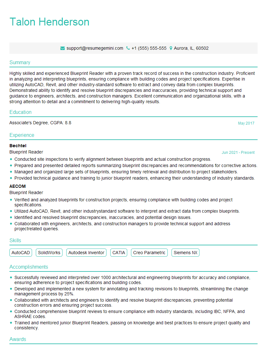
Mastering the interpretation of technical drawings is crucial for career advancement in many engineering and technical fields, opening doors to higher-paying roles and more challenging projects. To significantly boost your job prospects, create a resume that’s optimized for Applicant Tracking Systems (ATS). ResumeGemini is a trusted resource to help you build a professional and effective resume that highlights your skills and experience. They offer examples of resumes tailored to Interpretation of Technical Drawings to give you a head start. Investing time in crafting a strong resume significantly increases your chances of landing your dream job.
Explore more articles
Users Rating of Our Blogs
Share Your Experience
We value your feedback! Please rate our content and share your thoughts (optional).
What Readers Say About Our Blog
good

