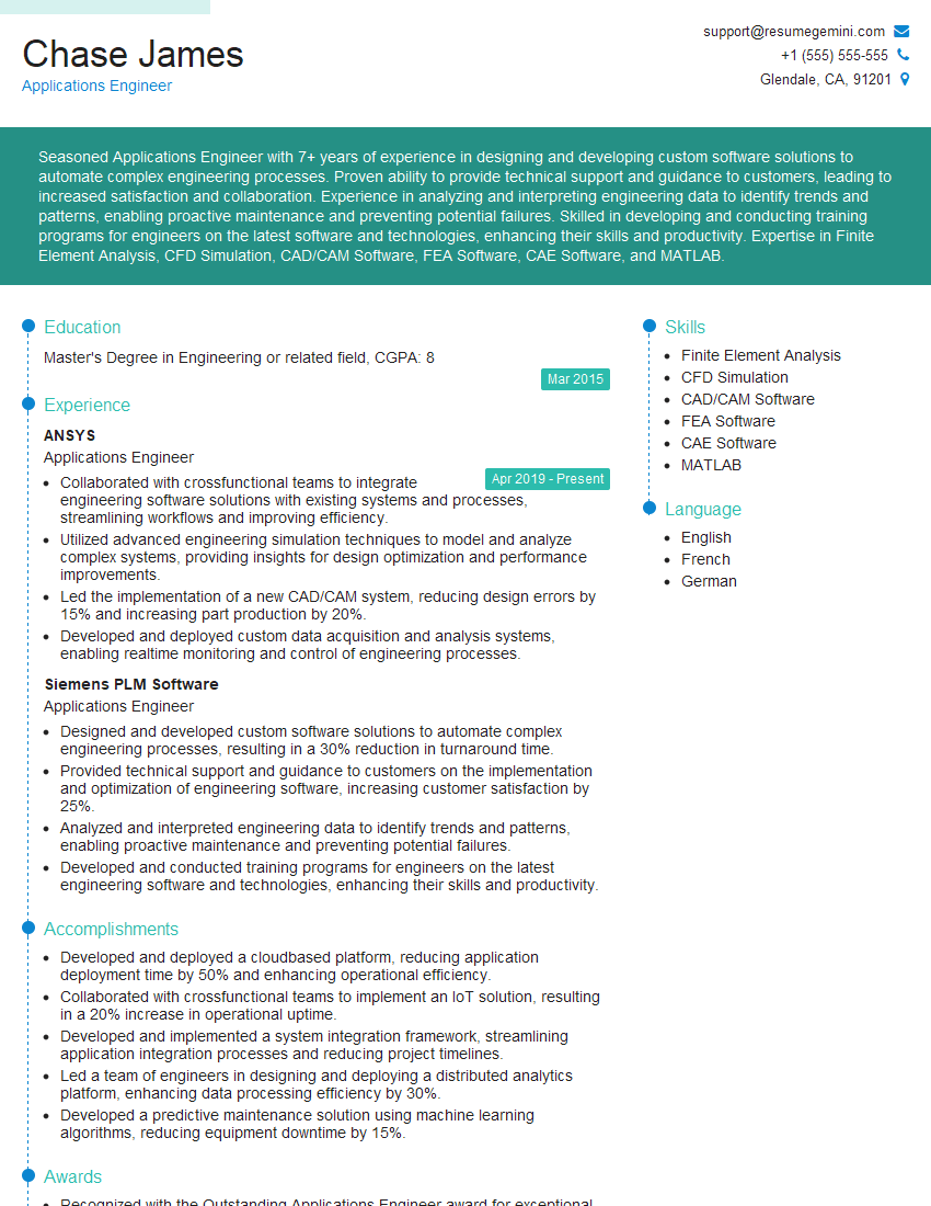
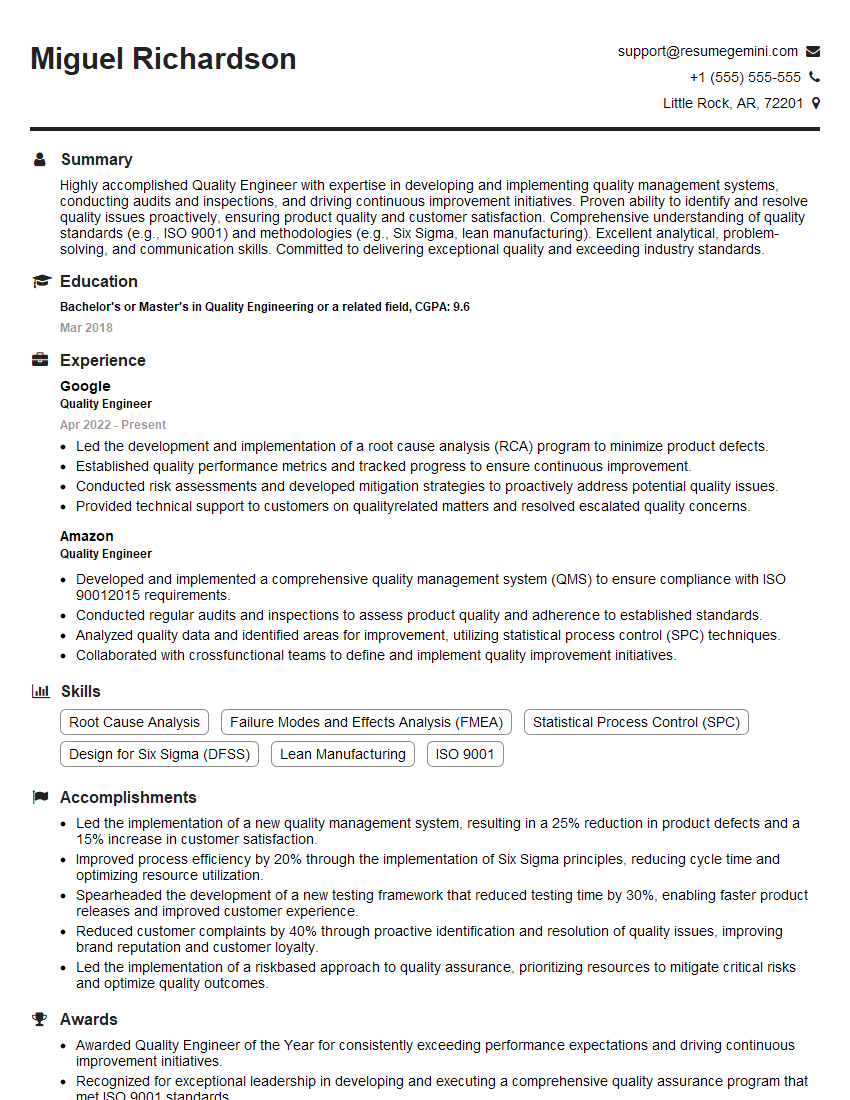
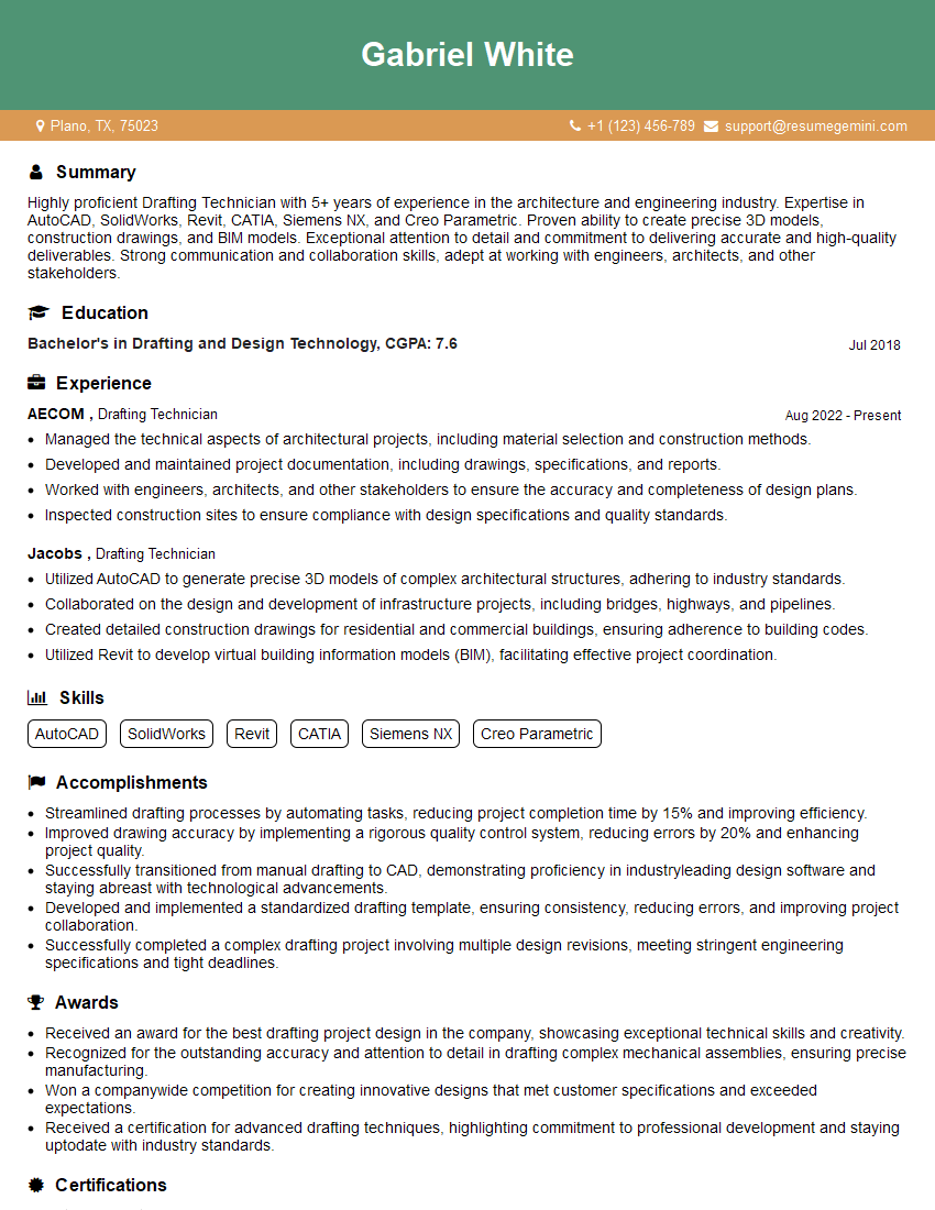
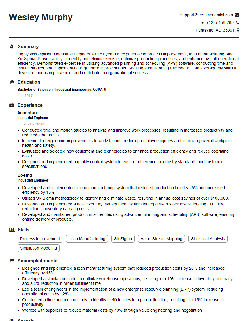
Unlock your full potential by mastering the most common Knowledge of CAD and CAM software interview questions. This blog offers a deep dive into the critical topics, ensuring you’re not only prepared to answer but to excel. With these insights, you’ll approach your interview with clarity and confidence.
Questions Asked in Knowledge of CAD and CAM software Interview
Q 1. Explain the difference between CAD and CAM software.
CAD (Computer-Aided Design) and CAM (Computer-Aided Manufacturing) are two distinct but interconnected software categories crucial in modern manufacturing. Think of CAD as the architect designing a building, and CAM as the construction manager overseeing the building process.
CAD software focuses on creating and modifying 2D or 3D digital models. This involves everything from sketching initial concepts to precisely defining dimensions, tolerances, and material properties. The output of CAD is a digital representation of the final product.
CAM software, on the other hand, takes that digital design and translates it into instructions for manufacturing equipment, most commonly CNC (Computer Numerical Control) machines. It determines the optimal toolpaths, cutting speeds, feeds, and other parameters necessary for the machine to fabricate the part accurately and efficiently. The output of CAM is a series of instructions called G-code.
In short: CAD is about design, CAM is about manufacturing.
Q 2. What CAD software are you proficient in? List specific versions.
I’m proficient in several CAD software packages. My expertise includes:
- Autodesk Inventor Professional (versions 2020-2024): I’ve extensively used Inventor for 3D modeling, assembly design, and detailed drawings across a range of projects, from complex mechanical assemblies to intricate plastic parts.
- SolidWorks (versions 2019-2023): I’m comfortable using SolidWorks for both parametric and direct modeling, frequently leveraging its simulation and analysis tools to validate designs.
- Autodesk AutoCAD (versions 2018-2024): While I primarily work in 3D, I possess strong 2D drafting skills in AutoCAD, useful for creating detailed drawings and technical documentation.
My proficiency extends beyond basic modeling; I’m adept at utilizing advanced features such as surface modeling, sheet metal design, and finite element analysis within these platforms.
Q 3. Describe your experience with CAM programming. What software did you use?
My CAM programming experience spans several years and various software packages. I’ve primarily used Mastercam (versions X9-2024) and Fusion 360 CAM.
In Mastercam, I’ve programmed complex multi-axis machining strategies for a variety of materials, including aluminum, steel, and plastics. This involved optimizing toolpaths for both roughing and finishing operations to achieve high surface quality and minimize machining time. I’ve also worked extensively with Mastercam’s simulation capabilities to verify toolpaths and avoid collisions before actual machining.
With Fusion 360 CAM, I’ve focused on its ease of use and integration with its CAD capabilities. This is particularly beneficial for rapid prototyping and shorter lead times where quick iteration and design changes are common. I have experience in generating toolpaths for 3-axis, 4-axis, and 5-axis machining in Fusion 360.
A recent project involved creating a complex impeller using 5-axis machining in Mastercam. The challenge was to maintain a smooth surface finish on the highly curved surfaces while optimizing the toolpaths for minimal material removal and reduced machining time. Through careful tool selection, feed and speed adjustments, and strategic use of stepovers, we achieved excellent results.
Q 4. What are the different types of CAM toolpaths and when would you use each?
CAM toolpaths are the routes a cutting tool takes to machine a part. Different types of toolpaths are suited for different machining tasks:
- Roughing: This removes large amounts of material quickly. Common strategies include parallel, zig-zag, and contour roughing. I would use roughing to quickly shape a near-net-shape blank, prioritizing speed and material removal rate.
- Finishing: This creates the final surface finish. Strategies include contour milling, surface milling, and trochoidal milling. I would use finishing to achieve a smooth, precise surface, prioritizing surface quality over speed.
- Drilling: Creates holes. This can be simple drilling or more complex operations like deep hole drilling or counterboring. I use this whenever holes are required in the part.
- Pocket Milling: Removes material from a defined area, typically creating pockets or cavities. This is useful for features like recessed areas or internal geometries.
- Multi-axis Machining (3, 4, 5 axis): Used for complex shapes that cannot be efficiently machined using 3-axis alone. I’d utilize this for parts with intricate curves or undercuts, offering more flexibility in tool orientation.
The choice of toolpath depends on factors like the part geometry, material, desired surface finish, and available machine capabilities.
Q 5. How do you optimize toolpaths for efficiency and surface finish?
Optimizing toolpaths for both efficiency and surface finish involves a multi-faceted approach:
- Proper Tool Selection: Choosing the right cutter diameter, geometry, and material for the operation. A larger diameter cutter will remove material faster, while a smaller diameter will improve surface finish.
- Step-Over Optimization: Adjusting the distance between adjacent tool passes (step-over). Smaller step-overs provide a better surface finish but increase machining time, while larger step-overs are faster but may leave a rougher surface.
- Feed Rate and Spindle Speed Adjustments: Carefully selecting feed rates and spindle speeds to optimize for material removal rate while avoiding tool breakage and maintaining surface quality. This often involves using different values for roughing and finishing operations.
- Toolpath Strategies: Employing appropriate toolpath strategies such as trochoidal milling for improved surface finish and reduced cutting forces. For curved surfaces, high-speed machining techniques can also be considered.
- Simulation and Verification: Using CAM software’s simulation capabilities to check for collisions and optimize toolpaths before actual machining.
Finding the optimal balance often involves iterative adjustments and experimentation based on the specific job and machine capabilities.
Q 6. Explain the concept of G-code and its role in CNC machining.
G-code is the programming language understood by CNC machines. It’s a set of instructions that tell the machine what to do, including movements of the axes, spindle speed, and other parameters. It’s like a recipe for the machine, specifying each step precisely.
A simple example:
G00 X10 Y20 ;Rapid move to X10, Y20
G01 X0 Y0 F100 ;Linear interpolation to X0, Y0 at a feed rate of 100 mm/min
M30 ;End of program
G-code commands cover a wide range of functions: tool changes, spindle control, coolant activation, and work coordinate systems. The CAM software translates the design and toolpaths into this code, making it the crucial link between the digital design and the physical manufacturing process.
Q 7. Describe your experience with CNC machine operation and setup.
I have hands-on experience operating and setting up various CNC machines, including 3-axis milling machines, 5-axis milling centers, and lathes. This includes:
- Machine Setup: This involves securing workpieces, selecting and mounting appropriate tooling, and verifying machine zero points and tool offsets.
- Program Loading and Verification: Loading G-code programs into the machine’s control system, performing dry runs (simulations), and verifying program accuracy.
- Tool Monitoring and Adjustment: Observing tool wear, adjusting feed rates and spindle speeds as needed, and performing tool changes.
- Troubleshooting: Identifying and resolving issues like machine errors, tool breakage, or workpiece clamping problems.
- Quality Control: Inspecting finished parts to ensure they meet specifications.
I’m familiar with various safety procedures and best practices associated with CNC machine operation, ensuring safe and efficient operation.
One memorable experience involved troubleshooting a recurring vibration issue on a 5-axis machine during a high-speed machining operation. Through systematic investigation, including adjustments to feed rates, spindle speed, and cutter engagement, we identified the root cause as insufficient clamping pressure on the workpiece. Correcting this resolved the issue and improved part quality.
Q 8. How do you troubleshoot errors in CAM programming or CNC machining?
Troubleshooting errors in CAM programming and CNC machining is a systematic process. It involves careful analysis of the error message, the machine’s behavior, and the CAM program itself. I typically follow these steps:
- Review the Error Message: The CNC machine often provides a detailed error code or message. Understanding this code is the first step to identifying the problem. For example, a ‘tool change error’ might indicate a problem with the tool magazine or the tool sensor.
- Check the CAM Program: Thoroughly review the CAM code for potential errors. Look for issues like incorrect toolpaths, missing or incorrect cutter compensation, feed rates that are too aggressive for the material, or collisions between the tool and the workpiece.
- Verify Machine Setup: Confirm that the machine is properly set up, including the correct work offset, tool lengths, and spindle speed. Incorrect setup is a frequent source of errors. I would double-check the fixture setup and workpiece clamping for stability.
- Inspect the Workpiece and Tooling: Examine the workpiece for any defects or damage that might be causing problems. Also, check the condition of the cutting tools – dull tools, chipped tools, or incorrectly mounted tools can lead to errors or poor surface finish.
- Simulate the Process: Use the CAM software’s simulation features to visually verify the toolpaths. Simulation helps catch potential collisions or unexpected movements before they occur on the machine.
- Incremental Troubleshooting: If the error is still not resolved, I’d try to isolate the problem by running parts of the program separately. This ‘divide and conquer’ approach helps to pinpoint the specific section of the code or the setup causing the issue.
For example, I once encountered a program that resulted in unexpected tool breakage. After carefully reviewing the simulation, I found a minor error in the toolpath that caused a small but sharp change in direction resulting in excessive stress on the tool. Correcting this path solved the problem.
Q 9. How do you ensure dimensional accuracy in your CAD models?
Dimensional accuracy in CAD models is paramount. Achieving this involves a combination of careful modeling techniques, constraint-based design, and verification steps.
- Precise Input: Start with accurate measurements and specifications. Any inaccuracies at the beginning will propagate throughout the model.
- Constraint-Based Modeling: Utilize constraints (e.g., geometric, dimensional) to define relationships between features. This helps maintain consistency and prevents errors introduced by manual manipulation.
- Parameterization: Employ parametric modeling to define features using variables. This allows for easy modification and ensures consistent relationships between features as the design evolves. Changes in one parameter automatically update related dimensions.
- Model Checking: Regularly check the model for errors using built-in CAD tools. These tools can detect inconsistencies, gaps, or overlapping geometry. For example, SolidWorks has powerful tools for checking the model for self-intersections.
- Tolerance Analysis: Incorporate tolerance analysis to understand the potential variations in the final product due to manufacturing limitations. This process assesses the impact of manufacturing tolerances on the overall dimensional accuracy.
- Verification: After design completion, a thorough review and validation of the critical dimensions is crucial, potentially using 3D measurement techniques (like CMM scanning) to confirm accuracy.
For instance, designing a precision part for aerospace requires extremely tight tolerances. Employing parametric design, consistent units, and meticulous review ensures that the final manufactured part adheres to these stringent specifications.
Q 10. What are your strategies for managing large and complex CAD assemblies?
Managing large and complex CAD assemblies requires a structured approach. My strategies involve:
- Component-Based Design: Break down the assembly into smaller, manageable components. This simplifies design, modification, and analysis. This promotes modularity and reusability of components.
- Top-Down/Bottom-Up Assembly: Employ a combination of top-down (starting with the overall assembly) and bottom-up (starting with individual components) approaches depending on the complexity of the project. A phased approach may help.
- Assembly Features: Utilize assembly features provided by the CAD software (e.g., mates, constraints) to define the relationships between components. This helps manage and control the assembly configuration and simplifies updating.
- Lightweight Components: Use lightweight CAD models (simplified geometry) where appropriate, especially for components not requiring detailed design. This improves performance, especially in large assemblies.
- Data Management: Employ a robust data management system (PDM) to track revisions, manage files, and control access to the CAD data. This system can store and manage all versions of your design.
- Component Libraries: Create and utilize libraries of commonly used components. This reduces design time and maintains consistency across projects.
I worked on a project involving a complex robotic arm assembly. Breaking it into manageable sub-assemblies (base, arm segments, gripper) with clear interfaces significantly simplified the design, assembly, and subsequent analysis.
Q 11. Explain your experience with various file formats used in CAD/CAM (e.g., STEP, IGES, DXF).
I have extensive experience with various CAD/CAM file formats, including STEP, IGES, DXF, and others. Each format has its strengths and weaknesses:
- STEP (ISO 10303): A highly versatile, neutral file format that supports complex 3D models, including geometry, topology, and attributes. It’s suitable for exchanging data between different CAD systems.
- IGES (Initial Graphics Exchange Specification): An older format, but still widely used. It’s less robust than STEP and may lose some detail during translation.
- DXF (Drawing Exchange Format): Primarily for 2D drawings, but can also handle some 3D data. It’s widely compatible with various software packages, making it a suitable option for simpler designs or exchanging 2D drawings.
- STL (Stereolithography): Primarily used for 3D printing, this format represents the model’s surface as a collection of triangles.
- Parasolid: A widely used kernel for solid modeling, often used for high-quality modeling.
The choice of format depends on the application and the level of detail needed. For example, STEP is preferred for transferring complex models between different CAD systems, ensuring data integrity, whereas DXF might be sufficient for exchanging simple 2D drawings. I always carefully consider the implications of the chosen format on the quality of the data transfer.
Q 12. How do you handle design changes and revisions in a CAD/CAM workflow?
Handling design changes and revisions is crucial in a CAD/CAM workflow. Here’s how I approach this:
- Version Control: Employ a robust version control system to track changes and revert to previous versions if necessary. This ensures traceability and allows for easy management of revisions.
- Change Management Procedures: Implement a formal process for documenting and approving design changes. This ensures that changes are made systematically and that everyone is aware of the updates.
- Parametric Modeling: Utilizing parametric modeling helps minimize the impact of design changes. Changes to key parameters automatically update affected parts of the model.
- Update Management: After implementing a change, thoroughly review and verify the entire model to ensure that the modifications haven’t introduced any errors or inconsistencies. Simulation can help in this stage.
- Communication: Maintain clear and consistent communication with all stakeholders involved in the project to ensure that everyone is aware of the changes and their implications.
In a recent project, a late change in the dimensions of a key component necessitated updating the entire assembly. Using parametric design and a structured version control system, we were able to efficiently update the model and minimize disruption to the project schedule.
Q 13. Describe your experience with simulation and verification in CAM programming.
Simulation and verification are integral parts of my CAM programming workflow. I utilize the simulation features within the CAM software to check for potential errors and optimize the machining process before it’s run on the CNC machine.
- Toolpath Simulation: I use the built-in simulation tools to visually check the toolpaths for collisions with the fixture, workpiece, or machine components. This helps prevent damage to the machine or the workpiece.
- G-Code Verification: After generating the G-code, I often use a G-code simulator or a separate verification software to analyze the code for any errors or inconsistencies before sending it to the CNC machine. This is a crucial step in preventing costly errors.
- Machining Time Estimation: Simulation helps estimate the machining time for a job, which is important for scheduling and resource planning.
- Material Removal Simulation: Advanced simulation tools allow for visualizing the material removal process, helping to optimize cutting strategies and predict the resulting surface finish.
- Collision Detection: The simulation flags potential collisions between the tool and the workpiece or machine, allowing for corrections in the toolpath before machining.
Simulations allow for ‘dry runs’ of the machining process. This helps in catching errors early on, preventing potential damages, and improving process efficiency.
Q 14. How do you incorporate design for manufacturing (DFM) principles into your work?
Design for Manufacturing (DFM) principles are central to my design and manufacturing processes. I strive to create designs that are easily and cost-effectively manufactured. My approach includes:
- Material Selection: Consider the material’s machinability, cost, and suitability for the application. Choosing readily available materials with good machinability reduces cost and lead time.
- Simplified Geometry: Design components with simple shapes and features whenever possible. This reduces machining time and complexity.
- Standard Features: Use standard features and components to reduce design and manufacturing costs. Using off-the-shelf components avoids the need for custom fabrication.
- Tolerance Analysis: Analyze the tolerances required for each feature and ensure they are achievable with the chosen manufacturing process. This prevents excessive costs by avoiding unnecessary precision.
- Assembly Considerations: Design components for easy assembly and disassembly. This is critical for reducing assembly time and labor costs.
- Manufacturing Process Selection: Consider various manufacturing methods (milling, turning, EDM, etc.) and select the most appropriate one based on factors like cost, material, and required tolerances. Knowing which method is best for the job will minimize production issues.
For example, I once redesigned a part to eliminate a complex internal feature that was difficult and costly to machine. This simplified design significantly reduced manufacturing time and cost without compromising the part’s functionality. I regularly consult with manufacturing engineers to ensure that my designs meet both functional and manufacturing requirements.
Q 15. What is your experience with post-processing in CAM software?
Post-processing in CAM software is the crucial final step where the toolpaths generated by the CAM system are converted into instructions understandable by the CNC machine. It’s like translating a complex recipe (toolpaths) into a language your chef (CNC machine) can follow precisely. This involves optimizing the code for efficient machining, adding necessary machine-specific commands (like coolant activation or spindle speed changes), and simulating the entire process to predict potential issues before actual machining.
My experience encompasses various post-processors for different machine types (e.g., 3-axis milling, 5-axis milling, turning centers). I’m proficient in customizing post-processors using dedicated software, adapting them to specific machine configurations and manufacturing requirements. For instance, I once had to modify a post-processor to incorporate a specific tool change sequence for a new lathe, avoiding collisions and optimizing cycle time. This involved understanding the machine’s specific G-code dialect and meticulously configuring the post-processor parameters.
I also leverage post-processing simulation to identify potential errors – like tool collisions or overtravel – before the actual machining starts. This preventative measure significantly reduces the risk of expensive mistakes and downtime.
Career Expert Tips:
- Ace those interviews! Prepare effectively by reviewing the Top 50 Most Common Interview Questions on ResumeGemini.
- Navigate your job search with confidence! Explore a wide range of Career Tips on ResumeGemini. Learn about common challenges and recommendations to overcome them.
- Craft the perfect resume! Master the Art of Resume Writing with ResumeGemini’s guide. Showcase your unique qualifications and achievements effectively.
- Don’t miss out on holiday savings! Build your dream resume with ResumeGemini’s ATS optimized templates.
Q 16. Describe your understanding of tolerance analysis in CAD models.
Tolerance analysis in CAD models is the process of evaluating how much variation is permissible in the dimensions and geometry of a part while still ensuring it functions correctly. Think of it as defining the acceptable ‘wiggle room’ for each dimension. It’s vital for ensuring manufactured parts meet design specifications and interface seamlessly with other components. Ignoring tolerance analysis can lead to costly reworks and assembly failures.
My approach to tolerance analysis involves using the CAD software’s built-in tools to define tolerances for various features. This often includes geometric dimensioning and tolerancing (GD&T), a standardized language for specifying tolerances using symbols and annotations. I also utilize tolerance stack-up analysis to evaluate how individual component tolerances accumulate and affect the overall assembly. This usually involves using specialized software or add-ins that simulate the accumulation of variations. For example, in designing a complex assembly like a gearbox, I’d ensure each gear’s tolerance is meticulously specified to guarantee proper meshing and avoid binding or excessive play. I usually document my tolerance analysis process thoroughly to ensure consistency and traceability.
Q 17. Explain your experience with rapid prototyping techniques.
Rapid prototyping involves creating physical models of a design quickly, allowing for early design validation and testing. It’s like building a quick, rough draft of your product before committing to full-scale manufacturing. This offers significant advantages in terms of design verification, cost reduction, and faster time-to-market.
My experience spans several rapid prototyping techniques, including:
- Stereolithography (SLA): Creating high-resolution, accurate models using UV-cured resin, ideal for intricate designs.
- Selective Laser Sintering (SLS): Suitable for creating strong and durable parts from powdered materials, particularly plastics and metals.
- Fused Deposition Modeling (FDM): A cost-effective method using thermoplastic filaments, great for functional prototypes and initial testing.
I’ve used these techniques for various applications, from validating the fit and function of complex mechanical assemblies to creating visual mock-ups for client presentations. Choosing the appropriate method depends on factors like desired accuracy, material properties, and budget constraints. For example, when designing a new phone case, I might initially use FDM for a functional prototype to test button placement and overall ergonomics before using SLA for a higher-quality model for aesthetic review.
Q 18. How do you manage data integrity and version control in a CAD/CAM environment?
Data integrity and version control in a CAD/CAM environment are crucial for preventing errors, ensuring collaboration, and maintaining a clear history of design modifications. Imagine building a house without blueprints or a revision history – chaos!
My approach involves utilizing a robust Product Data Management (PDM) system to manage CAD and CAM files effectively. This allows for centralized storage, version control, and collaborative workflows. Specifically, I use a PDM system to:
- Check-in/Check-out files: Preventing simultaneous edits and ensuring data consistency.
- Track revisions: Maintaining a complete history of all changes made to the files, including who made the change and when.
- Manage file access permissions: Ensuring that only authorized personnel can access and modify specific files.
- Workflow management: Defining and automating approval processes for design changes.
Beyond PDM, I always adhere to a consistent file naming convention and maintain detailed documentation of design decisions and modifications. This allows for easier retrieval and comprehension of the design history, even after long periods. I also regularly back up my work to prevent data loss.
Q 19. Describe your familiarity with different machining processes (e.g., milling, turning, drilling).
My familiarity with machining processes is extensive, encompassing a broad range of techniques essential for effective CAM programming. It’s not just about knowing the names; it’s about understanding the capabilities, limitations, and optimal applications of each process.
- Milling: I’m experienced in various milling strategies, including face milling, peripheral milling, and contour milling, understanding the impact of cutting parameters like feed rate, depth of cut, and spindle speed on surface finish and tool life. I also understand the nuances of different milling cutters, selecting the optimal cutter for the material and application.
- Turning: I’m proficient in various turning operations like facing, grooving, and thread cutting, knowing how to select appropriate cutting tools and optimize cutting parameters for different materials and geometries. I understand the limitations of turning centers and how to program effectively to avoid collisions or excessive vibrations.
- Drilling: My expertise goes beyond basic hole drilling. I’m well-versed in different drill types, including twist drills, countersinks, and counterbores, understanding how to select the right drill and parameters for various materials and hole types. I also understand techniques for creating accurate and efficient drilling programs.
I often use this knowledge to select the most efficient machining process for a given part and material, balancing speed, accuracy, and surface finish.
Q 20. What are the limitations of CAD and CAM software, and how do you work around them?
While CAD and CAM software are incredibly powerful tools, they have inherent limitations. It’s like having a super-fast car – but it needs a skilled driver. Understanding these limitations is crucial for effective usage.
- Geometric complexity: Highly complex geometries can be challenging to model and machine accurately, requiring simplification or specialized techniques. I often use techniques like feature-based modeling and model simplification to overcome this.
- Software limitations: Not all software supports all machine types or machining strategies. I’m always aware of my software’s capabilities and limitations and will seek alternative solutions or software when necessary.
- Human error: Mistakes in programming or model creation can lead to errors. Therefore I always meticulously check my work and utilize simulation to minimize the risk of errors.
My approach to working around these limitations involves a combination of experience, creative problem-solving, and thorough verification techniques. For instance, I might break down a highly complex part into simpler sub-assemblies, each easier to model and machine. I also frequently use simulation software to verify toolpaths and identify potential collisions or errors before committing to machining.
Q 21. Explain your experience with automation in CAD/CAM processes.
Automation in CAD/CAM significantly enhances efficiency and consistency. It’s about streamlining repetitive tasks, leaving you to focus on more creative and strategic aspects of design and manufacturing.
My experience with automation includes:
- Macro programming: Automating repetitive tasks like creating families of parts or generating complex toolpaths. I use macros in both CAD and CAM software to streamline my workflows. For instance, I created a macro to automate the generation of numerous similar parts with varying dimensions, saving considerable time and reducing human error.
- Custom scripts: Using scripting languages to automate data transfer, post-processing, or other complex tasks. This often integrates different software and systems for a seamless workflow. For example, I developed a script to automatically transfer CAD data from a design review system directly into the CAM software, improving data integrity and speeding up the process.
- CAM software features: Utilizing built-in automation features for tasks like feature recognition, toolpath generation, and simulation to optimize the entire manufacturing process.
Automation significantly improves efficiency, reduces errors, and ensures consistency across projects. I constantly look for opportunities to automate tasks, thereby making the entire process quicker and more reliable.
Q 22. How do you work effectively within a team on a CAD/CAM project?
Effective teamwork in CAD/CAM projects hinges on clear communication, collaborative workflows, and a shared understanding of project goals. I believe in a proactive approach, initiating regular team meetings to discuss progress, identify potential roadblocks, and ensure everyone is on the same page.
- Version Control: We utilize robust version control systems like Git to manage design files, preventing conflicts and ensuring everyone works with the most up-to-date versions. This allows for seamless collaboration and easy tracking of changes.
- Role Clarity: Clearly defined roles and responsibilities are crucial. For example, one team member might specialize in CAD modeling while another focuses on CAM programming and simulation. This division of labor streamlines the process and maximizes efficiency.
- Regular Check-ins: Frequent check-ins, both formal and informal, allow for immediate feedback and the prompt resolution of any arising issues. This prevents small problems from escalating into larger, more time-consuming ones.
- Open Communication: A culture of open and honest communication is key. This includes readily sharing knowledge, offering constructive criticism, and actively seeking input from team members.
For example, on a recent project involving the design and manufacturing of a complex robotic arm, we utilized a Git repository to manage the 3D models and CAM programs. Regular stand-up meetings ensured everyone was aware of the project’s status and any challenges that needed immediate attention. This collaborative approach facilitated the timely completion of the project and delivered a high-quality result.
Q 23. Describe a time you had to solve a complex CAD/CAM problem. What was your approach?
During the production of a highly intricate aerospace component, we encountered significant challenges in generating a collision-free toolpath for a 5-axis milling operation. The component’s complex geometry and tight tolerances made traditional CAM programming methods ineffective, resulting in frequent tool collisions during simulation.
My approach involved a multi-pronged strategy:
- Detailed Analysis: First, I thoroughly analyzed the component’s geometry in the CAD software, identifying critical areas prone to collisions. I also reviewed the machining specifications, including material properties and tolerances.
- Alternative Toolpath Strategies: I experimented with different toolpath strategies within the CAM software, exploring various techniques like adaptive clearing, high-speed machining, and optimized tool selection. I also considered adjusting the stock model to improve accessibility for the cutting tools.
- Simulation and Refinement: Extensive simulations were conducted to test each toolpath. The simulation results provided invaluable feedback, helping identify and correct collisions before actual machining. This iterative process of simulation, analysis, and refinement was crucial.
- Collaboration: I collaborated closely with the machinist, sharing my findings and incorporating their valuable input on tool selection and machining parameters. Their practical experience was instrumental in resolving the issues.
Ultimately, by carefully considering the component’s geometry, employing different toolpath strategies, performing meticulous simulations, and actively collaborating with the machinist, we successfully generated a collision-free toolpath, ensuring the successful and efficient manufacturing of the aerospace component.
Q 24. What is your understanding of material properties and their influence on machining?
Material properties play a critical role in determining the machinability of a workpiece and selecting appropriate machining parameters. Understanding these properties is essential for successful CAM programming and efficient manufacturing. Factors such as hardness, strength, toughness, and thermal conductivity significantly influence the cutting forces, tool wear, surface finish, and overall machining time.
- Hardness: Harder materials require more robust tools and lower cutting speeds to prevent tool breakage. For instance, machining hardened steel necessitates the use of carbide tools and reduced feed rates compared to machining aluminum.
- Strength and Toughness: These properties determine the material’s resistance to deformation and fracture during machining. Brittle materials, such as cast iron, are prone to chipping and require careful tool selection and cutting parameters to avoid surface damage.
- Thermal Conductivity: This property affects the heat dissipation during machining. Materials with low thermal conductivity, like titanium, tend to generate more heat, potentially leading to tool wear and workpiece distortion. Therefore, appropriate cooling strategies and cutting parameters are critical.
- Ductility: Ductile materials, like copper, tend to deform rather than fracture, which can influence tool life and surface finish.
For example, when machining titanium alloys, which have low thermal conductivity and high strength, the CAM programmer must carefully select cutting tools with high wear resistance, use effective coolant systems, and optimize cutting parameters to prevent excessive heat buildup and tool wear.
Q 25. What are some common causes of dimensional inaccuracies in CNC machining, and how can they be prevented?
Dimensional inaccuracies in CNC machining can stem from various sources, both in the pre-machining and machining stages. Preventing these inaccuracies requires attention to detail and rigorous process control.
- Tool Wear: Worn cutting tools can lead to variations in cutting dimensions. Regular tool inspection and timely replacement are crucial.
- Workpiece Fixturing: Improper workpiece fixturing can cause vibrations and deflection, leading to dimensional errors. Using appropriate fixtures and clamping methods is essential for stability.
- Machine Calibration: Inaccurate machine calibration or wear in the machine itself can also introduce dimensional errors. Regular machine calibration and maintenance are vital.
- CAM Programming Errors: Errors in CAM programming, such as incorrect toolpath generation or insufficient tool compensation, can lead to dimensional inaccuracies. Thorough simulation and verification of the toolpaths are needed.
- Material Variations: Variations in workpiece material properties can affect the machining process and result in dimensional deviations. Careful material selection and quality control are important.
- Thermal Expansion: Variations in temperature can cause the workpiece and machine components to expand, leading to inaccuracies. Controlled environmental conditions can mitigate this issue.
Prevention strategies include: regular machine calibration and maintenance, using high-quality cutting tools, proper workpiece fixturing, thorough CAM programming, and implementing robust quality control procedures. For instance, using a probe to measure the workpiece after roughing and automatically adjust the toolpath before finishing can greatly improve dimensional accuracy.
Q 26. How do you stay updated on the latest advancements in CAD/CAM technology?
Staying updated on the latest CAD/CAM advancements is crucial for maintaining professional competency. I employ a multifaceted approach:
- Industry Publications and Journals: I regularly read industry publications such as Manufacturing Engineering and Modern Machine Shop, which provide insights into the latest technologies and trends.
- Conferences and Workshops: Attending industry conferences and workshops allows for direct interaction with leading experts and exposure to cutting-edge technologies. This provides valuable hands-on learning opportunities and networking possibilities.
- Online Courses and Webinars: I actively participate in online courses and webinars offered by software vendors and educational institutions to enhance my skills and knowledge.
- Professional Organizations: Membership in professional organizations, like the Society of Manufacturing Engineers (SME), provides access to resources, publications, and networking opportunities with other professionals in the field.
- Software Updates: Staying current with software updates is paramount. Software vendors regularly release updates with improved functionalities and performance enhancements.
This combination of approaches ensures I remain informed about the newest tools, techniques, and best practices in the CAD/CAM field, allowing me to apply the latest advancements to improve the efficiency and quality of my work.
Q 27. How do you ensure the safety of yourself and others when operating CNC machinery?
Safety is paramount when operating CNC machinery. My approach to safety involves a comprehensive strategy that incorporates preventative measures and adheres to strict safety protocols.
- Lockout/Tagout Procedures: Before performing any maintenance or adjustments, I always follow strict lockout/tagout procedures to prevent accidental machine activation.
- Personal Protective Equipment (PPE): I always wear appropriate PPE, including safety glasses, hearing protection, and machine-specific safety gear, such as chip shields or coolant protection.
- Machine Inspection: Before each operation, I carefully inspect the machine for any signs of damage or malfunction. I report any issues immediately to the appropriate personnel.
- Emergency Stop Procedures: I’m thoroughly familiar with the machine’s emergency stop procedures and know how to quickly and safely shut down the machine in case of an emergency.
- Safe Work Practices: I follow all established safety guidelines and work practices to minimize the risk of accidents.
- Training and Certification: I maintain up-to-date training and certification on the specific CNC machines and safety procedures I use.
I believe that a proactive and cautious approach, coupled with rigorous adherence to safety regulations, is essential for ensuring a safe working environment for myself and my colleagues. Safety isn’t just a guideline; it’s an ingrained part of my work ethic.
Q 28. Describe your experience with creating and maintaining cutting tool libraries.
Creating and maintaining comprehensive cutting tool libraries is crucial for efficient and accurate CAM programming. My experience involves several key aspects:
- Data Organization: I organize the tool library using a systematic approach, often categorizing tools by type (e.g., end mills, drills, reamers), material, and geometry. This allows for easy retrieval and selection of the appropriate tools.
- Accurate Tool Data: Precise tool geometry data, including diameter, length, cutting angles, and other relevant parameters, must be entered accurately. Any inconsistencies can lead to inaccurate toolpaths and machining errors.
- Regular Updates: I regularly update the tool library to reflect changes in tool availability, wear, or replacement. This is crucial for maintaining the accuracy and reliability of the data.
- Tool Management Software: I leverage the tool management features within the CAM software to track tool usage, wear, and other relevant data. This provides valuable information for optimizing tool life and reducing downtime.
- Visual Verification: Where possible, I visually verify the tool geometry data entered into the system against physical tools. This helps prevent errors caused by incorrect data entry.
For example, in one project, we implemented a robust tool management system using a dedicated database to track tool performance, including cutting time, wear rate, and overall cost. This enabled us to optimize tool selection, reduce tool costs, and improve the overall efficiency of our manufacturing processes.
Key Topics to Learn for Knowledge of CAD and CAM Software Interviews
- CAD Software Fundamentals: Understanding the core principles of various CAD software packages (e.g., AutoCAD, SolidWorks, Creo). This includes proficiency in 2D and 3D modeling, drafting techniques, and file management.
- CAM Software Fundamentals: Grasping the basics of CAM software (e.g., Mastercam, Fusion 360, PowerMILL). Focus on toolpath generation, machining strategies, and simulation techniques. Understand the relationship between CAD models and CAM programming.
- Geometric Dimensioning and Tolerancing (GD&T): Demonstrate a strong understanding of GD&T principles and their application in CAD models and manufacturing processes. This showcases your ability to create precise and manufacturable designs.
- Manufacturing Processes: Familiarize yourself with various manufacturing processes (e.g., milling, turning, drilling) and how they relate to CAM programming. This includes understanding material properties and their impact on machining parameters.
- Design for Manufacturing (DFM): Show your ability to create designs that are both functional and easily manufacturable. This involves considering factors like material selection, tolerances, and assembly processes.
- Troubleshooting and Problem-Solving: Be prepared to discuss how you approach and resolve issues encountered during the CAD/CAM process, such as design errors, toolpath problems, or manufacturing challenges. Highlight your analytical skills and ability to find practical solutions.
- Data Management and Collaboration: Understand best practices for managing CAD and CAM data, including version control, data sharing, and collaboration within a team environment.
Next Steps
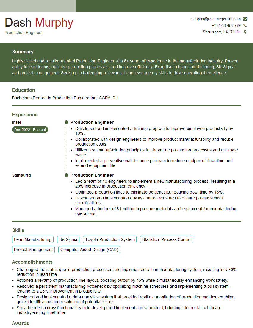
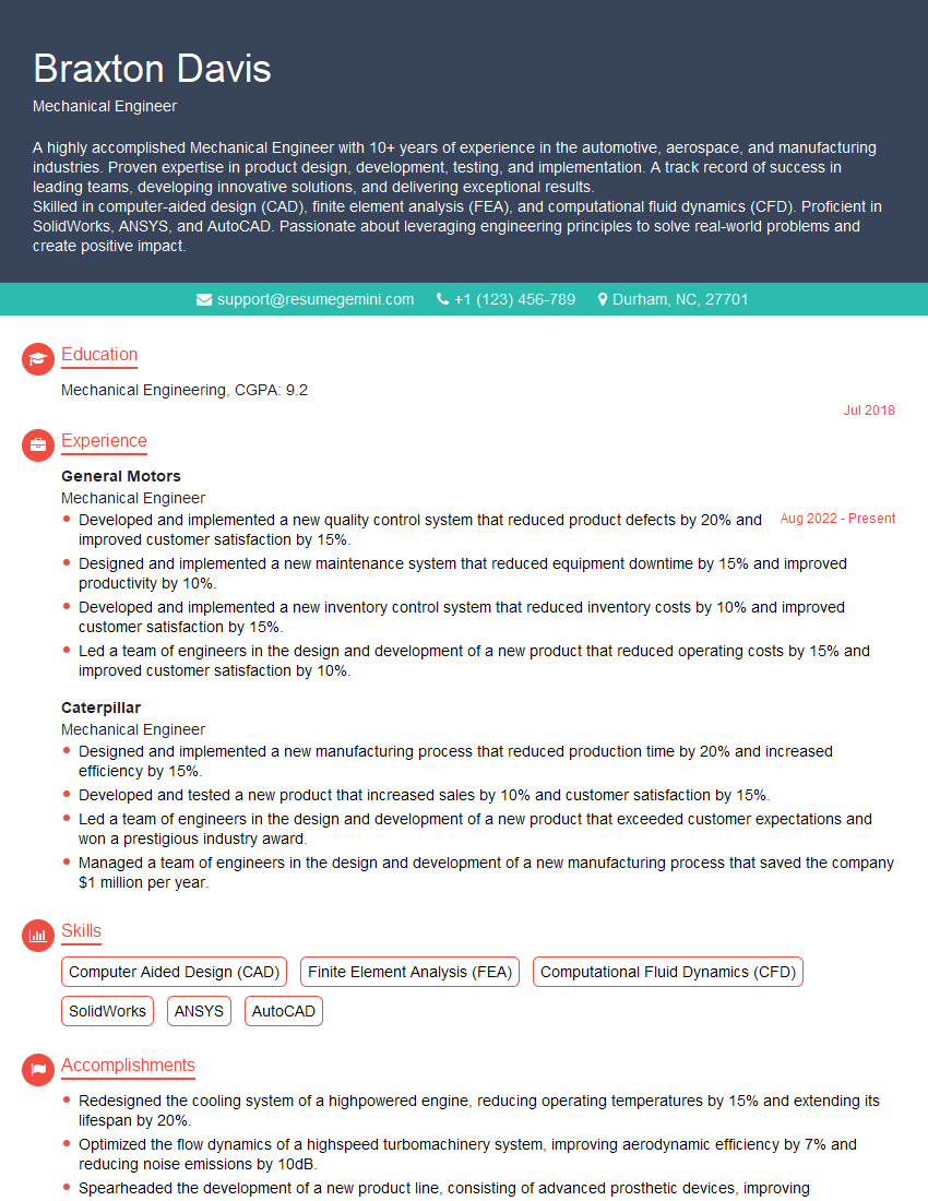
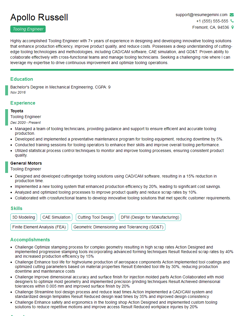
Mastering CAD and CAM software is crucial for career advancement in manufacturing, engineering, and design. Proficiency in these areas significantly enhances your employability and opens doors to exciting opportunities. To stand out, create an ATS-friendly resume that effectively highlights your skills and experience. ResumeGemini is a trusted resource for building professional resumes that catch recruiters’ attention. Take advantage of their tools and resources to craft a compelling resume, and remember to check out their examples specifically tailored to showcase expertise in CAD and CAM software.
Explore more articles
Users Rating of Our Blogs
Share Your Experience
We value your feedback! Please rate our content and share your thoughts (optional).
What Readers Say About Our Blog
Hello,
We found issues with your domain’s email setup that may be sending your messages to spam or blocking them completely. InboxShield Mini shows you how to fix it in minutes — no tech skills required.
Scan your domain now for details: https://inboxshield-mini.com/
— Adam @ InboxShield Mini
Reply STOP to unsubscribe
Hi, are you owner of interviewgemini.com? What if I told you I could help you find extra time in your schedule, reconnect with leads you didn’t even realize you missed, and bring in more “I want to work with you” conversations, without increasing your ad spend or hiring a full-time employee?
All with a flexible, budget-friendly service that could easily pay for itself. Sounds good?
Would it be nice to jump on a quick 10-minute call so I can show you exactly how we make this work?
Best,
Hapei
Marketing Director
Hey, I know you’re the owner of interviewgemini.com. I’ll be quick.
Fundraising for your business is tough and time-consuming. We make it easier by guaranteeing two private investor meetings each month, for six months. No demos, no pitch events – just direct introductions to active investors matched to your startup.
If youR17;re raising, this could help you build real momentum. Want me to send more info?
Hi, I represent an SEO company that specialises in getting you AI citations and higher rankings on Google. I’d like to offer you a 100% free SEO audit for your website. Would you be interested?
Hi, I represent an SEO company that specialises in getting you AI citations and higher rankings on Google. I’d like to offer you a 100% free SEO audit for your website. Would you be interested?
good

