Every successful interview starts with knowing what to expect. In this blog, we’ll take you through the top Mechanical Assembly Drawings interview questions, breaking them down with expert tips to help you deliver impactful answers. Step into your next interview fully prepared and ready to succeed.
Questions Asked in Mechanical Assembly Drawings Interview
Q 1. Explain the purpose and importance of Mechanical Assembly Drawings.
Mechanical assembly drawings are the blueprints for building a machine or device. They’re crucial because they provide a comprehensive visual representation of how individual parts fit together to form a complete assembly. Think of it like a recipe for a complex machine: it tells you exactly what ingredients (parts) you need, in what quantities, and how to combine them to create the final product. Without them, manufacturing would be chaotic and inefficient.
Their importance lies in several key areas:
- Manufacturing Guidance: They guide the manufacturing process, ensuring that parts are assembled correctly and consistently.
- Communication: They serve as a clear communication tool between designers, engineers, and manufacturing personnel.
- Quality Control: They facilitate quality control by providing a reference point for inspecting the finished assembly.
- Maintenance and Repair: They are invaluable for maintenance and repair, enabling technicians to easily disassemble, inspect, and reassemble the device.
- Documentation: They form part of the vital product documentation, ensuring the design is preserved and understood.
Q 2. What are the different types of views used in assembly drawings (e.g., isometric, orthographic)?
Assembly drawings utilize various views to represent the three-dimensional nature of the assembly. The most common types are:
- Orthographic Views: These are two-dimensional projections of the object onto three mutually perpendicular planes (top, front, and side). They are accurate and detailed but can be challenging to visualize the assembly’s three-dimensional form. Imagine looking at the object from different directions and drawing what you see on a flat surface.
- Isometric Views: This is a pictorial representation that shows all three dimensions in a single view, offering a more intuitive understanding of the assembly’s spatial arrangement. The angles of the axes are usually 120 degrees. Think of it like a slightly distorted photograph.
- Exploded Views: These illustrate the assembly’s components separated slightly, showing the relationship and order of assembly. They are excellent for understanding the assembly sequence and how parts interlock. Think of it like a parts diagram of a toy.
- Section Views: These views show an internal structure by cutting through the assembly. This helps in visualization of complex internal components and their arrangement.
Q 3. Describe the standard symbols and conventions used in assembly drawings.
Standard symbols and conventions ensure consistency and clarity in assembly drawings. These symbols are internationally recognized and reduce ambiguity. Here are some key examples:
- Dimensioning: Uses specific methods for indicating lengths, diameters, angles, and other measurements.
- Tolerances: Indicates the permissible variations in dimensions and geometry (discussed further below).
- Surface Finish Symbols: Shows the required surface roughness or texture of a part.
- Material Specifications: Indicates the material from which a part is made (e.g., steel, aluminum, plastic).
- Welding Symbols: Show the type and location of welds in a welded assembly.
- Sectioning Lines: Used to indicate where a sectional view is taken.
- Hidden Lines: Used to represent features that are not directly visible in a particular view. They are usually dashed lines.
- Center Lines: Used to show the center of circular or symmetrical features; usually made with alternating long and short dashes.
These are just a few examples, and the specific conventions may vary slightly depending on the relevant standards used (e.g., ASME Y14.5 in the US, ISO standards internationally).
Q 4. How are tolerances and fits indicated on assembly drawings?
Tolerances and fits specify the allowable variations in the dimensions of mating parts. A tolerance defines the acceptable range of variation from a nominal dimension, while a fit describes how closely two parts fit together. They are crucial for ensuring the assembly functions correctly.
Tolerances are usually indicated using plus/minus values (+/-). For example, a dimension of 10 mm +/- 0.1 mm means the actual dimension can vary between 9.9 mm and 10.1 mm.
Fits are often defined using designations such as:
- Clearance Fit: There is a gap between mating parts (e.g., shaft in a hole).
- Interference Fit: The parts are forced together, creating a tight connection (e.g., press-fit).
- Transition Fit: The fit can be either clearance or interference depending on the actual dimensions of the parts.
These fits are often specified with letter and number designations according to standards like ISO 286.
Q 5. What is GD&T (Geometric Dimensioning and Tolerancing) and how is it applied in assembly drawings?
Geometric Dimensioning and Tolerancing (GD&T) is a symbolic language used to define and control the geometric form and positional relationships of parts. It goes beyond simple dimensional tolerances by specifying the permissible variations in form, orientation, location, and runout of features.
GD&T uses symbols like:
- Straightness: Controls the straightness of a feature.
- Flatness: Controls the flatness of a surface.
- Circular Runout: Controls the variation in the circularity of a rotating part.
- Position: Controls the location of a feature relative to a datum.
- Perpendicularity: Controls the perpendicularity of a feature to a datum.
Using GD&T in assembly drawings significantly improves the precision and clarity of the design specifications, ensuring that manufactured parts meet the required functional requirements. This is particularly important for complex assemblies where precise alignment and fit are critical.
For example, instead of just specifying a hole’s diameter, GD&T might specify the hole’s diameter, position tolerance relative to another feature, and cylindricity to ensure precise location and shape.
Q 6. Explain the significance of bill of materials (BOM) in assembly drawings.
The Bill of Materials (BOM) is an integral part of an assembly drawing. It’s a comprehensive list of all the components required to build the assembly. It includes details such as part numbers, descriptions, quantities, and material specifications for each part. Think of it as a shopping list for building the machine.
Its significance is multifaceted:
- Manufacturing Planning: It is essential for manufacturing planning, enabling the procurement of necessary parts and the scheduling of the manufacturing process.
- Cost Estimation: It allows for accurate cost estimation by providing a complete list of parts and their quantities.
- Inventory Management: It assists with inventory management, tracking the availability of parts and ensuring timely replenishment.
- Assembly Guidance: In conjunction with the drawing, it ensures that all necessary components are available for assembly.
Q 7. How do you interpret a parts list within an assembly drawing?
A parts list, often integrated within the assembly drawing or provided separately as a BOM, contains a structured summary of all the components used in the assembly. Interpreting it requires careful attention to detail.
Typically, a parts list contains:
- Part Number: A unique identifier for each component.
- Description: A brief description of the part.
- Quantity: The number of each part required for the complete assembly.
- Material: The material of the component.
- Reference Designators: These are letters or numbers added to each part in the assembly drawing. These allow you to directly link the part to its location in the drawing, making it easier to understand how individual parts fit within the larger assembly.
By correlating the part numbers, descriptions, and reference designators between the parts list and the assembly drawing, you can quickly locate and identify every component and its position in the final product. This is crucial for assembly, manufacturing, and maintenance.
Q 8. Explain the difference between a detailed drawing and an assembly drawing.
A detailed drawing focuses on a single component, providing all the necessary information for its manufacture. Think of it as a blueprint for a single part. It shows dimensions, tolerances, material specifications, surface finishes, and other crucial details needed for a machinist or fabricator to create that part. An assembly drawing, on the other hand, shows how multiple components fit together to form a complete assembly. It shows the relationship between parts, often including simplified representations of individual components, focusing on their relative positions and interactions within the larger system. It’s like an architect’s plan showing how different rooms fit into a house.
Example: A detailed drawing might show the precise dimensions and tolerances of a bolt, while an assembly drawing would show how that bolt is positioned within an engine block along with other related parts.
Q 9. How are exploded views used in assembly drawings?
Exploded views are a powerful tool in assembly drawings. They illustrate the components of an assembly in a separated, layered manner, revealing the order of assembly and the spatial relationships between parts. This makes it much easier to understand how the parts go together and helps avoid misinterpretations. Imagine taking apart a clock and laying all its parts out – an exploded view does the same thing visually.
Example: In an exploded view of a bicycle, the wheels, frame, handlebars, and pedals might be slightly separated but shown connected by lines to indicate their correct positions in the assembled bicycle. This is incredibly helpful for assembly, maintenance, and even troubleshooting.
Q 10. What are section views and why are they used?
Section views are used to reveal internal features of a component or assembly that would otherwise be hidden in a standard view. Imagine slicing through an object with a plane – a section view shows you the cross-section revealed by that imaginary cut. They’re particularly useful when showing complex internal geometries or features hidden within an assembly.
Types: There are various types of section views like full section, half-section, broken-out section, and revolved section, each chosen based on the complexity and the information to be conveyed. They help clarify intricate designs and aid in manufacturing processes.
Example: A section view of a pipe might show the internal diameter and the thickness of its walls, information crucial for selecting appropriate materials and for the overall design.
Q 11. Describe your experience with different CAD software used for creating assembly drawings (e.g., SolidWorks, AutoCAD, Creo).
Throughout my career, I’ve extensively used SolidWorks, AutoCAD, and Creo for creating assembly drawings. SolidWorks excels in creating and managing complex assemblies, especially those involving parametric modeling and detailed simulations. AutoCAD’s strength lies in its 2D drafting capabilities, which are indispensable for generating detailed drawings and precise dimensions for manufacturing. Creo offers a robust platform for both 2D and 3D modeling, and it’s particularly well-suited for large-scale projects requiring advanced assembly management and collaborative design. My experience with these packages allows me to choose the best tool for the specific task at hand, whether it’s a simple assembly or a complex system.
Example: For a quick assembly of simple parts, AutoCAD might suffice. However, for a complex mechanism with intricate moving parts requiring simulations and analyses, SolidWorks would be the preferred choice.
Q 12. How do you handle revisions and updates to assembly drawings?
Revision control is crucial for ensuring that everyone works with the latest, accurate version of an assembly drawing. We typically use a revision numbering system, often following a standard like ISO 10208, to track changes. Each revision is documented, specifying the changes made, the date, and the author. We use a revision cloud to highlight areas where changes have been made on the drawing itself. This system prevents confusion and ensures that everyone is on the same page. Version control software integrated within the CAD system itself also helps to manage revisions effectively.
Example: Revision A might include initial design specifications, Revision B might address a minor dimensional change, and Revision C might reflect a material substitution.
Q 13. How do you ensure the accuracy and clarity of assembly drawings?
Ensuring accuracy and clarity requires meticulous attention to detail at every stage. This involves using consistent annotation styles, clear dimensioning, and appropriate tolerances. Regular quality checks, including peer reviews, are essential to catch potential errors. Using the right tools, including proper CAD software and appropriate measurement equipment, is important. Furthermore, adhering to established drafting standards and best practices is paramount. This ensures that the drawing is unambiguous and readily understood by anyone involved in the manufacturing process. For instance, ensuring that dimensions are clearly placed, tolerances are specified correctly, and notes are concise and informative is critical.
Q 14. Describe your process for creating detailed assembly drawings from 3D models.
My process for creating detailed assembly drawings from 3D models typically involves these steps:
- Model Review: First, I thoroughly review the 3D model to understand its functionality, component interactions, and overall design.
- Component Extraction: I extract individual components from the assembly and generate detailed drawings for each, ensuring that all critical dimensions, tolerances, and material specifications are included.
- Assembly View Creation: I then create various assembly views, including exploded views and section views, as needed to clearly depict the relationships between parts.
- Annotation and Dimensioning: I add annotations, dimensions, and notes to the assembly drawing, ensuring clarity and readability. I pay close attention to proper dimensioning practices to avoid ambiguity.
- Bill of Materials (BOM) Generation: I create a comprehensive bill of materials listing all components, part numbers, quantities, and materials.
- Review and Approval: I conduct a thorough review of the drawings and BOM, followed by a peer review for quality control before final release.
This systematic approach ensures that the resulting assembly drawing is accurate, comprehensive, and readily understandable by all stakeholders.
Q 15. Explain how you would identify potential assembly issues from an assembly drawing.
Identifying potential assembly issues from an assembly drawing involves a systematic review process. Think of it like a detective investigating a crime scene – you need to carefully examine every detail to find potential problems before they arise during actual assembly.
Component Interference: I meticulously check for clashes between parts. For example, two components might be positioned too closely, preventing proper mating. I often use 3D modeling software to visually verify clearances.
Missing or Incorrect Fasteners: I carefully verify the number, type, and size of all fasteners (bolts, screws, rivets, etc.) are specified and readily accessible. A missing bolt or using an incorrect size can halt assembly.
Improper Part Orientation: I examine the orientation of each part to ensure they are positioned correctly for assembly. A simple mistake in orientation can cause major problems. I often use annotations to check for part orientation like keyways, notches or other features.
Accessibility Issues: I assess whether all components can be accessed and assembled easily. If a part is hidden or difficult to reach, it might require redesign or a different assembly sequence. A step-by-step simulated assembly in CAD software helps tremendously.
Clearance and Tolerance Analysis: I check for adequate clearances and ensure tolerances are properly specified and compatible between mating parts. Insufficient clearance can lead to binding or jamming.
By combining a thorough visual inspection with a thoughtful review of tolerances, materials, and assembly sequence, I anticipate and prevent many potential problems.
Career Expert Tips:
- Ace those interviews! Prepare effectively by reviewing the Top 50 Most Common Interview Questions on ResumeGemini.
- Navigate your job search with confidence! Explore a wide range of Career Tips on ResumeGemini. Learn about common challenges and recommendations to overcome them.
- Craft the perfect resume! Master the Art of Resume Writing with ResumeGemini’s guide. Showcase your unique qualifications and achievements effectively.
- Don’t miss out on holiday savings! Build your dream resume with ResumeGemini’s ATS optimized templates.
Q 16. How do you incorporate design changes and feedback into existing assembly drawings?
Incorporating design changes and feedback into existing assembly drawings requires careful attention to detail and version control. Imagine it as updating a detailed map – a small change can have ripple effects throughout the whole system.
Revision Control: I always use a robust revision control system (like a PDM or CAD software’s built-in system) to track changes. Each revision includes a clear description of the modification and its impact.
Updated Bill of Materials (BOM): Any changes to parts necessitate updating the BOM to reflect the new part numbers, specifications, and quantities. This ensures everyone is working with the latest information.
Geometric Dimensioning and Tolerancing (GD&T) Updates: Changes to dimensions or tolerances require careful review of GD&T annotations to maintain the functionality and fit of the assembly. This includes updating the tolerances of features that are affected by the design changes.
Redlining and Markup Tools: I utilize CAD software’s redlining and markup tools to clearly indicate the location and nature of modifications to the assembly drawing. This helps the team and manufacturer understand the changes. I clearly differentiate between proposed changes and finalized revisions.
Communication and Collaboration: Effective communication with the design team, manufacturing personnel, and other stakeholders is crucial to ensure that everyone is aware of the changes and understands their implications.
By following this structured approach, I ensure that design changes are properly documented and implemented, minimizing errors and delays.
Q 17. Describe your experience with creating and reading assembly drawings for complex mechanisms.
I have extensive experience creating and reading assembly drawings for complex mechanisms, ranging from intricate robotics systems to precision instruments. This experience taught me the value of clear, concise communication through visual representation.
For example, I worked on a project involving a complex automated assembly line. The mechanisms involved hundreds of parts, requiring multiple levels of sub-assemblies. This needed meticulous organization within the drawings, utilizing techniques like exploded views to show the assembly sequence and hierarchical structures to manage the complexity. We employed 3D modeling extensively to verify clearances and potential interference issues. I used detailed callouts and annotations to highlight critical features and tolerances.
Reading complex assembly drawings necessitates a methodical approach. I start by understanding the overall function of the mechanism and then systematically analyze each sub-assembly, tracing the flow of components and identifying their interactions. I frequently utilize section views and detailed callouts to understand the internal workings.
Q 18. How do you manage large and complex assembly drawings efficiently?
Managing large and complex assembly drawings efficiently requires a combination of organizational skills and the right tools. Think of it like organizing a large library – you need a system to locate information quickly and prevent chaos.
Modular Design Approach: Breaking down the assembly into smaller, manageable modules simplifies the creation and management of individual drawings. This mirrors a divide-and-conquer strategy.
Hierarchical Structure: Utilizing a hierarchical structure within the CAD software to organize the assembly drawing in a logical manner allows for easy navigation and retrieval of specific components or sub-assemblies.
Data Management System (PDM): Employing a PDM system allows for efficient version control, collaborative editing, and central data storage of all assembly drawings and associated documents.
Exploded Views and Assembly Sequences: Generating exploded views helps visualize the assembly process, while assembly sequences clarify the order of operations, making troubleshooting and assembly much easier.
Automated BOM Generation: Using automated BOM generation tools within CAD software drastically reduces manual error and keeps the BOM consistently updated with the drawing.
By adopting these strategies, I can effectively manage even the most complex assembly drawings, ensuring accuracy, consistency, and efficiency.
Q 19. What are some common errors to avoid when creating assembly drawings?
Several common errors can compromise the clarity and functionality of assembly drawings. Avoiding these pitfalls is crucial for successful manufacturing and assembly.
Incomplete or Inconsistent Dimensioning: Missing or conflicting dimensions can lead to misinterpretations and manufacturing errors. Always double check for consistency.
Ambiguous or Missing Annotations: Unclear or missing annotations can result in confusion regarding material specifications, surface finishes, or assembly instructions.
Incorrect Scale or Orientation: Using the wrong scale or orientation can render the drawing unusable or lead to assembly problems. Always verify the scale and orientation before finalizing.
Lack of Clear Assembly Sequence: Failing to provide a clear assembly sequence can make assembly difficult, time-consuming, and prone to errors.
Ignoring Tolerance Stack-up: Not accounting for tolerance stack-up (the accumulation of tolerances from individual parts) can result in parts not fitting together properly. This requires a thorough tolerance analysis.
By carefully reviewing the drawing and paying close attention to detail, I minimize these errors.
Q 20. How do you ensure compliance with relevant industry standards and regulations?
Ensuring compliance with relevant industry standards and regulations is paramount in mechanical design. This is not just about following rules, but about safety, functionality, and legal compliance.
I familiarize myself with the applicable standards early in the project lifecycle. This might include ISO standards for drawings, material specifications (e.g., ASTM), or industry-specific regulations. I incorporate these standards directly into the drawing creation process. This includes using standardized symbols, annotations, and formatting. For example, GD&T symbols are applied according to ASME Y14.5 standards. I also maintain a detailed record of all the standards used in the project documentation.
Regular audits and reviews ensure ongoing compliance. I use checklists and templates to confirm that the drawings and specifications adhere to the standards. This proactive approach minimizes risks and ensures that the design meets all necessary regulatory requirements.
Q 21. How do you interpret callouts and annotations within assembly drawings?
Interpreting callouts and annotations within assembly drawings requires a deep understanding of drafting conventions and symbols. It’s like deciphering a code – each symbol and notation has a specific meaning.
I begin by understanding the context of the annotation. What is it referring to? What information is it conveying? I familiarize myself with various symbols and their meaning (e.g., surface finish symbols, GD&T symbols). I understand the importance of reading the title block, revision history and notes sections of the drawing. Each symbol and annotation is usually clearly defined using a legend or a parts list. GD&T symbols, for example, require careful attention to understand tolerances and required geometric control.
For example, a callout might specify the material type, surface finish, or a particular dimension. I meticulously analyze each annotation to fully understand its implications for the assembly.
Q 22. Explain your understanding of different assembly methods (e.g., welding, bolting, riveting).
Different assembly methods offer various strengths and weaknesses, impacting the final product’s strength, cost, and manufacturing time. Let’s examine three common methods:
Welding:
This is a permanent joining method that fuses two or more metal parts using heat and pressure, sometimes with filler material. It’s ideal for creating strong, rigid assemblies. Think of the frame of a car – welded joints provide exceptional structural integrity. However, welding can cause distortion, require skilled labor, and might leave visible seams. Different welding techniques exist (e.g., MIG, TIG, spot welding) each suited for specific materials and applications.
Bolting:
Bolting uses threaded fasteners to join parts. It’s a highly versatile method offering easy disassembly, making maintenance and repairs simpler. Imagine assembling a piece of furniture – bolts allow for easy adjustments and reconfigurations. However, bolted joints can be weaker than welded ones, susceptible to loosening over time (requiring regular checks and potential lock-washers), and might require more space than a welded joint.
Riveting:
Riveting involves inserting a rivet (a pin) through the joined parts and deforming its end to secure the connection. It’s a permanent joining technique often used where vibration resistance is crucial, such as in aircraft construction. While strong, riveting is labor-intensive, and the joined parts are permanently fastened.
The choice of assembly method depends heavily on factors such as the material properties, required strength, tolerance, cost, and need for future disassembly. A thorough understanding of each method is vital for effective design and manufacturing.
Q 23. How would you interpret a drawing with surface finish specifications?
Surface finish specifications on a drawing are crucial for functionality, aesthetics, and cost. They dictate the texture and quality of a part’s surface. I interpret these specifications by looking for symbols, codes, and numerical values, often referencing standards like ISO or ANSI.
For example, a surface might be specified as Ra 6.3. ‘Ra’ stands for average roughness, measured in micrometers (µm). 6.3 µm indicates a relatively rough surface. Other specifications might indicate surface treatments like plating, powder coating, or anodizing. These treatments affect corrosion resistance, appearance, and wear resistance. I ensure the selected finish is appropriate for the intended function of the part. A highly polished surface might be needed for a mirror, while a rougher surface might be suitable for increased friction in a gripping mechanism. Careful consideration of these specifications is essential to ensure the manufactured part meets the design intent.
Q 24. How do you use assembly drawings to troubleshoot assembly problems?
Assembly drawings are my roadmap for troubleshooting. When facing assembly problems, I systematically use the drawing to pinpoint the root cause.
My approach involves:
- Detailed Comparison: I compare the physical assembly with the drawing, paying close attention to part numbers, dimensions, orientations, and tolerances. Any deviation becomes a potential problem area.
- Tolerance Analysis: I check if the misalignment or interference falls within the specified tolerances. Exceeding tolerances might require adjustments or part replacement.
- Part Identification: The drawing helps identify the specific components involved in the problem. This helps isolate the faulty or incorrectly installed part.
- Assembly Sequence Verification: I review the assembly sequence depicted in the drawing (often illustrated through exploded views). Incorrect sequence can be a common cause of issues.
- Geometric Dimensioning and Tolerancing (GD&T): Understanding GD&T symbols on the drawing enables me to analyze the permissible variations in part dimensions and their impact on assembly.
For instance, if a part doesn’t fit, I’d check the drawing for dimensional discrepancies, tolerance stack-up, and ensure the correct part is being used. I would also verify the sequence of assembly to check for potential collision or interference.
Q 25. What are your strategies for effectively communicating technical information through drawings?
Effective communication through drawings involves clarity, consistency, and adherence to standards. My strategies include:
- Clear and Concise Annotations: I use precise and unambiguous language for dimensions, tolerances, materials, and surface finishes.
- Logical Layout: I organize drawing elements logically, ensuring parts are easily identifiable and their relationships are clear. Using standard views (front, top, side) is essential.
- Appropriate Scale: Choosing the correct scale ensures all details are visible while maintaining a manageable drawing size.
- Detailed Views and Sections: I utilize detailed views (close-ups) and section views to showcase hidden features and internal structures.
- Exploded Views and Assembly Sequences: I incorporate these to visualize the assembly process, simplifying understanding and preventing errors.
- Standard Symbols and Conventions: Following relevant standards (e.g., ASME Y14.5) ensures the drawing is universally understood.
- Revision Control: I implement a revision control system to track changes and ensure all stakeholders work with the most up-to-date drawing.
For example, using a consistent numbering system for parts and clear labeling of materials helps avoid misinterpretations. I also ensure that dimensions are clearly indicated and that any special instructions are highlighted.
Q 26. How familiar are you with different drawing projection systems?
I’m familiar with various drawing projection systems, primarily first-angle and third-angle projections.
First-Angle Projection:
In first-angle projection, the view is projected onto a plane behind the object. It is less common in North America but still used in some parts of the world.
Third-Angle Projection:
Third-angle projection is the most widely used system in North America and many other regions. In this system, the view is projected onto a plane in front of the object. This allows for easier visualization of the assembly process.
Understanding these systems is crucial to correctly interpreting and creating assembly drawings. Misinterpreting the projection system can lead to significant errors in the construction process. I always verify the projection system used in a drawing before proceeding with any analysis or interpretation.
Q 27. Describe your experience with creating and using assembly drawing templates.
I have extensive experience creating and using assembly drawing templates. Templates streamline the creation process, ensuring consistency and reducing errors. They typically include pre-defined elements like title blocks, standard views, and common symbols and annotations.
My use of templates includes:
- Customization: I tailor templates to specific project needs, adding company logos, standard materials, and relevant specifications.
- Revision Management: Templates often incorporate revision blocks, simplifying tracking changes and maintaining drawing history.
- Consistent Formatting: Templates ensure consistency in dimensions, annotations, and overall presentation across multiple drawings.
- Efficiency: Pre-populated templates significantly reduce the time required to create new drawings.
For example, I’ve used templates for creating electrical cabinet drawings, incorporating standard panel layouts, and using pre-defined symbols for components like switches, relays and circuit breakers. This significantly reduced the time taken to create new drawings and ensured consistency in the presentation. This is especially beneficial in larger projects involving multiple draftsmen.
Q 28. How do you handle discrepancies between the drawing and the physical assembly?
Discrepancies between drawings and physical assemblies are a serious concern that requires immediate attention. My approach focuses on careful investigation and documentation.
My process involves:
- Verification: I independently verify the discrepancy using multiple methods (measurements, comparison with other drawings, and consultation with other team members).
- Root Cause Analysis: I systematically investigate the possible causes, including drawing errors, manufacturing defects, incorrect assembly procedures, or outdated documentation.
- Documentation: I meticulously document the discrepancy, including photos, measurements, and observations. This documentation is crucial for future reference and for communication with relevant stakeholders.
- Corrective Action: Based on the root cause analysis, I propose corrective actions, which might include updating the drawing, implementing improved manufacturing processes, issuing revised assembly instructions, or initiating a non-conformance report.
- Communication: I communicate the findings and corrective actions to the relevant team members (design engineers, manufacturing personnel, quality control) promptly to ensure timely resolution.
For instance, if the physical dimensions of a part do not match the drawing, I might investigate manufacturing tolerances, check for potential design flaws, or verify the measurement tools used. The goal is to pinpoint the error and implement the appropriate corrective measures. Proper documentation of the discrepancy, the root cause and the corrective action is very important to prevent this happening again.
Key Topics to Learn for Mechanical Assembly Drawings Interview
- Understanding Drawing Schematics: Mastering the interpretation of different views (orthographic, isometric, sectional) and their relationship to the assembled product. Practice identifying components and their spatial relationships.
- Bill of Materials (BOM) Interpretation: Learn to effectively use BOMs to identify all components, their quantities, and specifications. Practice cross-referencing BOM information with the drawing itself.
- Geometric Dimensioning and Tolerancing (GD&T): Understand the symbols and their implications for acceptable variations in dimensions and form. Practice interpreting GD&T callouts on drawings to ensure proper assembly.
- Fastener and Joining Methods: Familiarize yourself with various types of fasteners (bolts, screws, rivets, welds) and their applications. Understand the implications of different joining techniques on assembly procedures and tolerances.
- Assembly Sequencing and Procedures: Develop a clear understanding of how to logically sequence the assembly process based on the drawing. Consider the practical implications of component fit and accessibility.
- Tolerance Stack-up Analysis: Learn to analyze how individual component tolerances accumulate to impact the final assembly’s functionality and dimensions. This is a crucial skill for ensuring proper fit and function.
- Material Identification and Properties: Know how to identify materials used in the assembly from the drawing annotations and understand how material properties influence assembly techniques and potential challenges.
- Working Drawings vs. Assembly Drawings: Clearly distinguish between these drawing types and understand their roles in the overall product development process.
- Problem-Solving and Troubleshooting: Practice identifying potential assembly issues by analyzing drawings. Develop your ability to propose solutions for common problems encountered during assembly.
Next Steps
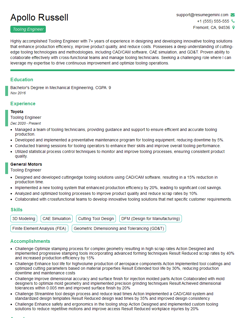
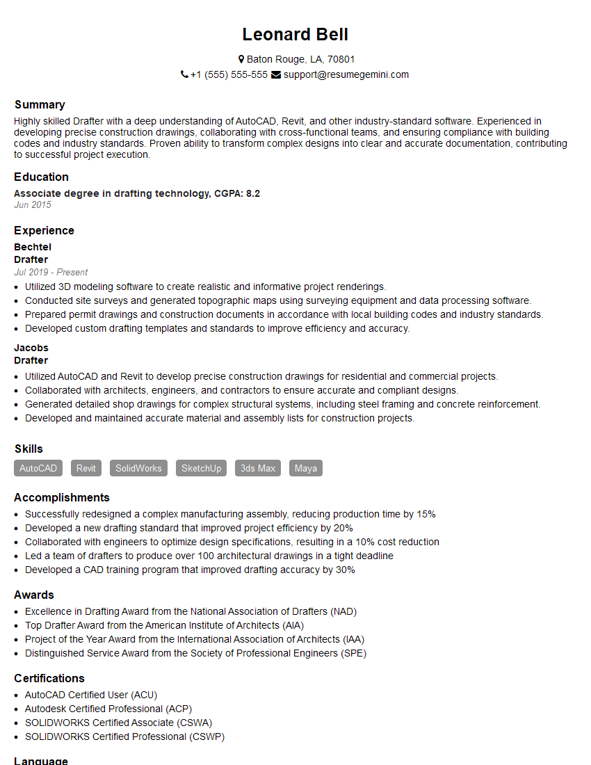
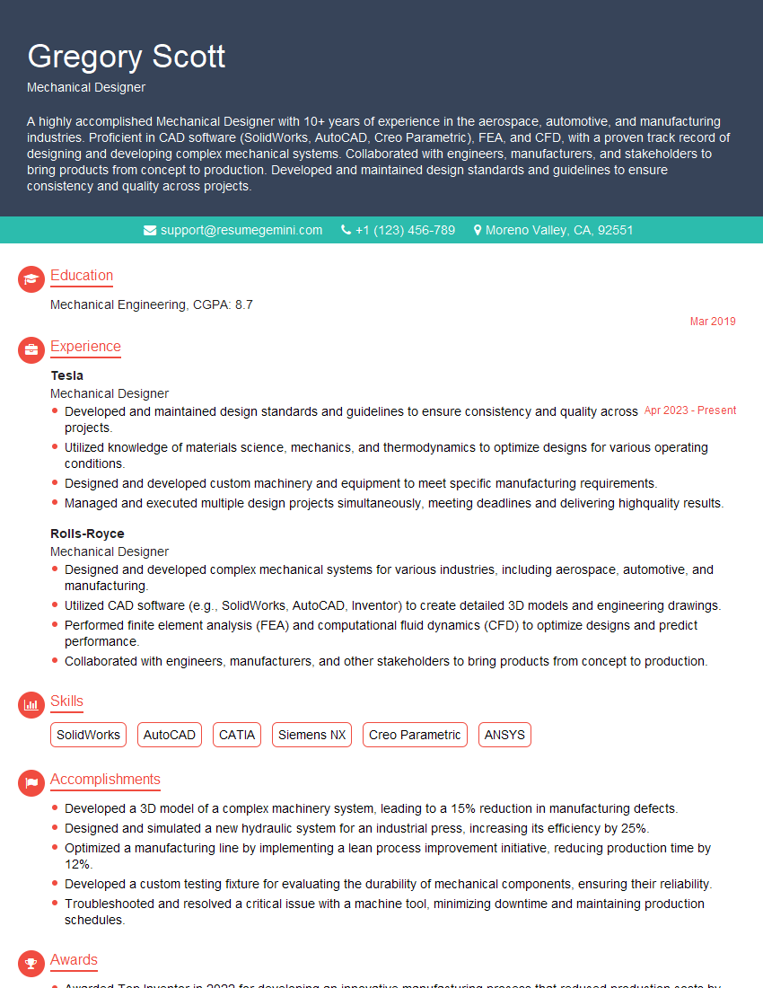
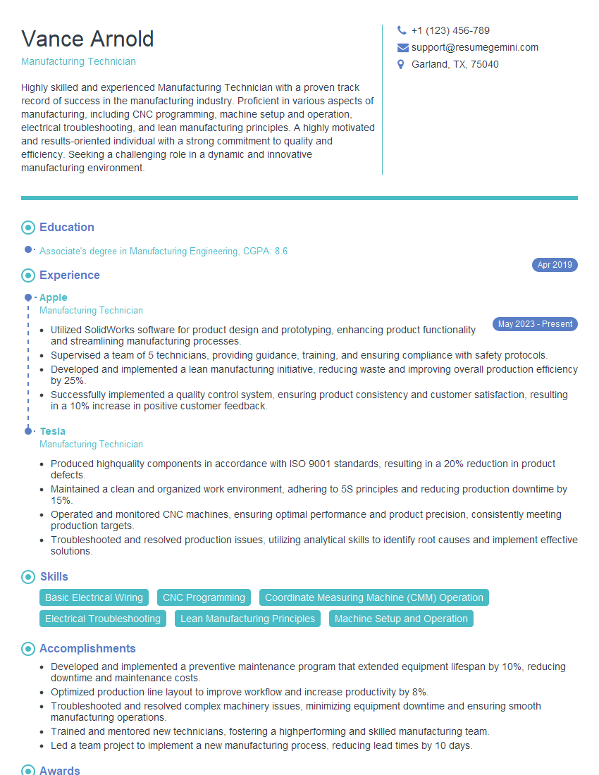
Mastering Mechanical Assembly Drawings is crucial for success in many engineering roles, demonstrating your ability to translate technical documentation into practical action. This skill is highly valued and directly contributes to efficient and effective manufacturing processes. To maximize your job prospects, creating a strong, ATS-friendly resume is essential. ResumeGemini can help you build a professional and impactful resume that showcases your skills effectively. We offer examples of resumes tailored to Mechanical Assembly Drawings professionals to help you get started.
Explore more articles
Users Rating of Our Blogs
Share Your Experience
We value your feedback! Please rate our content and share your thoughts (optional).
What Readers Say About Our Blog
Hi, I represent an SEO company that specialises in getting you AI citations and higher rankings on Google. I’d like to offer you a 100% free SEO audit for your website. Would you be interested?
good
