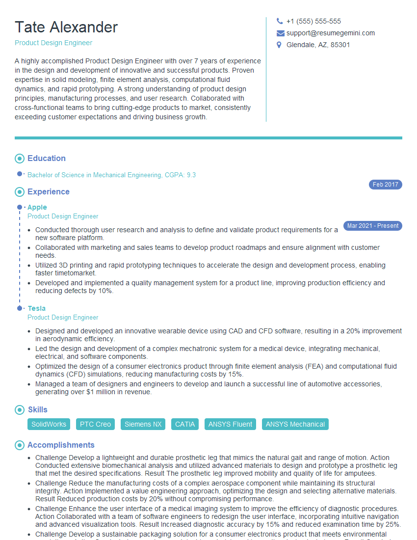
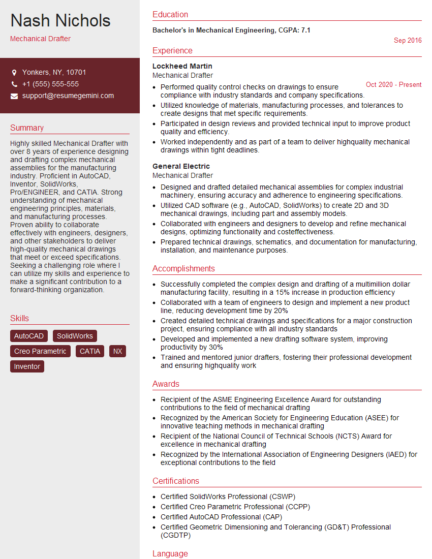
Feeling uncertain about what to expect in your upcoming interview? We’ve got you covered! This blog highlights the most important Mechanical Drawings and Specifications interview questions and provides actionable advice to help you stand out as the ideal candidate. Let’s pave the way for your success.
Questions Asked in Mechanical Drawings and Specifications Interview
Q 1. Explain the difference between orthographic and isometric projections.
Orthographic and isometric projections are two different ways of representing a 3D object in a 2D drawing. Orthographic projection uses multiple views (typically top, front, and side) to show the object from different perspectives, each view showing only two dimensions. Imagine unfolding a box – each side is an orthographic view. Isometric projection, on the other hand, attempts to show all three dimensions in a single view. It’s a pictorial representation where all three axes are equally foreshortened, creating a perspective that’s easier to visualize but can sometimes be less precise for detailed measurements.
Orthographic Projection: Excellent for precise measurements and detailed representation. It’s the standard for technical drawings, allowing for clear communication of dimensions and features. Think of an architect’s blueprint – it’s almost entirely orthographic.
Isometric Projection: Useful for quick visualization and communication of the object’s overall shape and form. It’s often used for illustrations or conceptual designs where precise measurements aren’t as critical. Think of a simple hand-drawn sketch depicting a machine part; isometric projection makes that much easier.
The key difference lies in their purpose: orthographic projections prioritize accuracy and detail, while isometric projections prioritize visual understanding and quick representation.
Q 2. Describe your experience with different CAD software packages (e.g., AutoCAD, SolidWorks, Creo).
My experience spans several leading CAD software packages. I’m highly proficient in AutoCAD, utilizing its 2D drafting capabilities extensively for creating detailed drawings, schematics, and layouts. My experience includes managing large drawing sets, implementing layers and blocks for efficiency, and employing various annotation tools for precise labeling and dimensioning.
Beyond AutoCAD, I have considerable experience with SolidWorks and Creo Parametric. SolidWorks is my preferred choice for 3D modeling, allowing me to design complex parts and assemblies with ease. I’m adept at creating realistic renderings, conducting simulations, and generating manufacturing-ready drawings directly from the 3D model. Creo, similarly, allows for powerful 3D modeling and assembly design, and I’ve used it extensively on large-scale projects, particularly where collaborative design and data management were critical. My skills include surface modeling, finite element analysis integration, and detailed design documentation using Creo’s tools.
I am confident in adapting my skills to any CAD software, readily adopting new features and workflows as needed to meet the requirements of any project. My strength lies not just in proficiency with individual tools but in understanding how to leverage the strengths of each platform for optimal results.
Q 3. How do you ensure accuracy and precision in your drawings?
Accuracy and precision are paramount in mechanical drawings. My approach is multi-faceted and begins with careful planning. I use precise measurements and adhere strictly to specified tolerances. This involves employing several techniques:
- Using calibrated instruments: I always ensure I use properly calibrated measuring tools like calipers, micrometers, and rulers.
- Employing proper CAD techniques: Using constraints and parameters in 3D modeling software ensures that changes in one area automatically update dependent elements, minimizing errors. Precise dimensioning and utilizing parametric modeling are key.
- Dimensional analysis and checks: I always cross-reference dimensions and perform rigorous checks using internal software tools to catch inconsistencies early. This includes verifying geometric relationships and clearances.
- Adherence to standards: Strictly following relevant industry standards (like ASME Y14.5, discussed later) ensures consistency and minimizes ambiguity.
- Peer reviews: I believe in the value of peer review; having a colleague check drawings before release provides an extra layer of quality control. This catches small mistakes and inconsistencies.
By employing these methods, I ensure drawings are not only accurate but also consistent and easily understood by others.
Q 4. What are the different types of dimensioning and tolerancing standards you are familiar with (e.g., ASME Y14.5)?
I’m familiar with several dimensioning and tolerancing standards, most prominently ASME Y14.5. This standard is crucial for defining the allowable variations in dimensions and geometric features of parts and assemblies. It uses a system of geometric dimensioning and tolerancing (GD&T) which goes beyond simple plus/minus tolerances.
ASME Y14.5: This standard provides a structured approach to specifying tolerances, including size tolerances (limits on dimensions), form tolerances (straightness, flatness), orientation tolerances (perpendicularity, parallelism), location tolerances (position, concentricity), and runout tolerances. It utilizes symbols and notations for clear and unambiguous communication.
ISO standards: I’m also acquainted with the corresponding ISO standards, which often mirror ASME Y14.5 but have slight variations in terminology or notation. Understanding the differences between ASME and ISO standards is critical for working in international contexts.
Beyond these, my experience includes applying other relevant standards depending on the project’s context, for example, industry-specific standards within aerospace or automotive manufacturing.
Q 5. Explain the importance of proper sectioning techniques in mechanical drawings.
Proper sectioning techniques are essential for clearly illustrating internal features of a part that would otherwise be hidden in an external view. They avoid cluttered and confusing drawings, enabling clear communication of internal geometries and details.
Several types of sections exist, including:
- Full Section: A complete cut through the object, revealing the internal details.
- Half Section: A section cut through half of the object, often combined with an external view to show both internal and external features.
- Broken-out Section: A small section cut away to reveal a specific feature without completely sectioning the entire part.
- Revolved Section: Used for symmetrical parts, rotating a section to display features in a single view.
- Removed Section: A section of the part is drawn separately, providing a detailed view.
Choosing the appropriate sectioning technique depends on the complexity of the part and the information needing to be conveyed. For example, a half-section is ideal for showing symmetrical parts, while a broken-out section is useful for highlighting specific internal features in an assembly without obscuring surrounding elements.
Q 6. How do you create and interpret detailed assembly drawings?
Creating and interpreting detailed assembly drawings involves several critical steps. It begins with understanding the function of the assembly and its individual components. Each part needs to be accurately modeled and positioned within the assembly, ensuring proper clearances and interfaces.
Creation:
- Part Modeling: Individual parts are first designed and modeled using CAD software.
- Assembly Modeling: Parts are then assembled virtually, often utilizing constraints (mates) to define their relative positions and relationships.
- Exploded Views: Generating exploded views provides a clear illustration of the assembly sequence and shows the relationship between individual components.
- Bill of Materials (BOM): A BOM is a critical part of the assembly drawing, listing all components and their quantities.
- Annotation: Clear and concise annotations, including dimensions, tolerances, material specifications, and surface finishes are essential.
Interpretation: Interpreting assembly drawings requires a detailed understanding of the components, their arrangement, and the specified tolerances. The drawing should provide all information needed for manufacturing, assembly, and maintenance.
A well-executed assembly drawing acts as a comprehensive instruction manual for the assembly’s creation, maintenance, and understanding.
Q 7. What are your experiences with GD&T (Geometric Dimensioning and Tolerancing)?
My experience with GD&T (Geometric Dimensioning and Tolerancing) is extensive. I understand and apply its principles to ensure that parts are manufactured to meet precise specifications while accommodating necessary variations. GD&T goes beyond simple plus/minus tolerances, considering the form, orientation, location, and runout of features.
Practical Application: I’ve used GD&T to define the permissible variations in critical features like mating surfaces, ensuring proper fit and function. This includes specifying tolerances for features like flatness, parallelism, perpendicularity, and position. For instance, specifying a positional tolerance with a maximum material condition (MMC) ensures the part will always fit, even at its largest permissible size. Using GD&T on drawings avoids ambiguity and ensures consistent interpretations by manufacturers.
Benefits: GD&T reduces manufacturing costs by allowing more tolerance on less critical features. It promotes clear communication between designers and manufacturers, reducing the chances of misinterpretation. Furthermore, it improves product quality and reliability by ensuring proper fit and functionality of components.
Q 8. Describe your process for creating detailed part drawings including views, sections, and dimensions.
Creating detailed part drawings involves a systematic approach to ensure clarity and accuracy. It starts with a thorough understanding of the part’s function and requirements. I begin by sketching initial concepts to solidify the design before moving to the CAD software. The process then follows these steps:
- Creating Views: I typically start with a minimum of three orthographic views (front, top, and right side) to fully represent the part’s geometry. Additional views, such as auxiliary views or detailed views, are added as needed to clarify complex features. For instance, if a part has an intricate internal feature, a sectional view would be essential.
- Adding Sections: Sections are critical for showing internal features that are not visible in external views. I use appropriate section lines and hatching to clearly illustrate these features. For example, a revolved section can clearly show a hole’s path through a complex part.
- Dimensioning: Precise dimensioning is paramount. I follow dimensioning standards, ensuring dimensions are clear, unambiguous, and sufficient for manufacturing. This includes using appropriate dimensioning techniques, like chain, baseline, or coordinate dimensioning, depending on the part’s complexity. I always ensure that dimensions are placed logically and avoid redundant dimensions.
- Adding Tolerances: To ensure manufacturability, tolerances are added to critical dimensions, specifying the acceptable range of variation. The choice of tolerance depends on the manufacturing process and the function of the part. Geometric Dimensioning and Tolerancing (GD&T) symbols may be used to define form, orientation, location and runout.
- Adding Material and Finish Specifications: The drawing includes details such as the material used (e.g., steel, aluminum, plastic) and surface finish requirements (e.g., roughness, plating). This ensures the part is manufactured correctly.
Throughout this process, I maintain a consistent style and adhere to relevant drawing standards (like ASME Y14.5) to guarantee uniformity and clarity across all my drawings. Think of it like building with LEGOs – each brick (dimension, view, detail) needs to be precisely placed for the final structure (the part) to be sound and functional.
Q 9. How do you handle revisions and updates to existing drawings?
Handling revisions and updates to existing drawings requires a meticulous and organized approach to maintain accuracy and control. I employ a revision control system, typically using a revision block within the drawing itself. Each revision is assigned a unique revision number (e.g., A, B, C) and a description of the changes made. This allows for easy tracking of changes over time. This is crucial for traceability and accountability.
For example, if a design change necessitates modifying a dimension, I’ll update the drawing, increment the revision number, and clearly document the alteration in the revision block. This revision history is vital for maintaining accurate records and ensuring everyone is working with the most up-to-date version. I also maintain a central repository (often a dedicated server or cloud-based system) for storing and accessing drawings, enforcing version control and preventing accidental overwrites.
Moreover, a formal change management process is usually followed, involving review and approval by relevant stakeholders before implementing any revisions in the actual manufacturing process. This helps avoid costly errors or discrepancies downstream.
Q 10. Explain the importance of drawing standards and their consistency in a project.
Drawing standards, like ASME Y14.5 in the US or ISO standards internationally, are essential for ensuring consistency and clarity in engineering drawings. They provide a common language and framework for communicating design information across different teams, companies, and even countries.
Consistency is paramount because it minimizes ambiguity and misinterpretations. Imagine trying to assemble a product if each part’s drawing used a different dimensioning style or notation – chaos would ensue. Standards eliminate this problem. They dictate everything from line weights and lettering styles to the way dimensions and tolerances are specified. They also standardize the way views, sections, and other drawing elements are represented.
The benefits of adhering to standards are numerous. They reduce errors, simplify communication, improve efficiency, and ensure that parts manufactured from different drawings can be easily assembled. In short, adhering to drawing standards is crucial for successful project execution and ensuring the final product meets its design specifications. It’s like following a recipe – using standardized ingredients (drawing standards) ensures a consistent, reliable outcome (the manufactured part).
Q 11. Describe your experience with BOM (Bill of Materials) creation and management.
Creating and managing a Bill of Materials (BOM) is a crucial aspect of mechanical design. A BOM is a comprehensive list of all the components required to manufacture an assembly. It details each component’s part number, description, quantity, and material. My experience involves utilizing CAD software’s built-in BOM generation capabilities, which automatically extracts component information from the assembly model.
The process usually begins with the creation of individual part drawings and the subsequent assembly of these parts in a CAD environment. Once the assembly is complete, the software generates a BOM. This often needs some manual refinement to ensure accuracy and completeness. I verify the accuracy of the BOM by cross-referencing it with the individual part drawings and potentially using spreadsheets to further manage and track the data.
For complex assemblies, I’ve used specialized software to manage the BOM, allowing for features like version control, automated part number generation, and integration with manufacturing and procurement systems. Effective BOM management is vital for cost estimation, procurement planning, and production efficiency. A well-managed BOM prevents costly material shortages or overstocking.
Q 12. How do you manage large and complex assemblies in a CAD environment?
Managing large and complex assemblies in a CAD environment requires employing strategic techniques to maintain performance and organization. These assemblies can contain thousands of parts, making efficient management crucial. My approach focuses on the following:
- Modular Design: I favor a modular design approach, breaking down the assembly into smaller, more manageable sub-assemblies. This makes it easier to work on individual parts or sections without affecting the entire model. Think of it like building a car – working on the engine separately from the body.
- Component Management: I use component libraries to store frequently used parts, reducing redundancy and ensuring consistency across different assemblies. This is similar to having a well-organized toolbox.
- Assembly Constraints: I utilize CAD software’s constraint tools to define the relationships between parts, ensuring accurate assembly and avoiding geometrical conflicts. This is like using guides or templates when assembling furniture.
- Top-Down/Bottom-Up Assembly: Choosing the appropriate assembly approach (top-down or bottom-up) depends on the complexity of the assembly. Top-down starts with the main assembly and then adds sub-assemblies and parts; bottom-up starts with individual parts and combines them into sub-assemblies, culminating in the final assembly. The best approach is often project specific.
- Configuration Management: I use tools within the CAD software to manage different configurations or versions of the assembly. This is essential for projects that have multiple variants or options.
Efficient management of large assemblies reduces the likelihood of errors, improves productivity, and simplifies the revision process.
Q 13. How familiar are you with different drawing file formats (e.g., .dwg, .dxf, .prt)?
I am proficient in various drawing file formats commonly used in the mechanical engineering industry. Here are a few examples:
- .dwg: The native file format for Autodesk AutoCAD, a widely used CAD software. This is one of the most common formats, offering excellent compatibility.
- .dxf: A neutral file format that allows for data exchange between different CAD software packages. While less feature-rich than .dwg, its compatibility is essential for interoperability.
- .prt: A file format associated with PTC Creo Parametric, another widely used CAD software. It’s their native format, often including more detailed design data than the neutral formats.
- .step/.stp: Neutral file format for 3D models, useful for transferring data between different CAD systems.
- .iges/.igs: Another neutral file format for 3D models, providing interoperability between different CAD programs.
My experience covers both working with these formats and converting between them to accommodate various design processes and collaboration needs. Understanding the nuances of each file format ensures smooth collaboration and data exchange with different stakeholders.
Q 14. How do you ensure drawings are compliant with relevant industry standards and regulations?
Ensuring drawings comply with industry standards and regulations is crucial for safety, functionality, and legal reasons. This involves a multi-step process:
- Identifying Applicable Standards: First, I identify the relevant standards and regulations based on the industry, application, and geographical location of the product. This might include ASME, ISO, ANSI, or other regional standards.
- Incorporating Standards into the Design: During the design process, I actively incorporate these standards into the drawings. This includes using standardized symbols, dimensioning techniques, and tolerance specifications. This is a proactive measure, reducing the need for significant modifications later.
- Regular Audits and Reviews: Regular audits and reviews of drawings are conducted to ensure compliance. This could involve internal checks or external audits by third-party inspection agencies, depending on the project’s requirements.
- Software Tools and Checklists: Software tools can often be utilized to automate compliance checks, flagging potential issues automatically. Checklists are also employed to verify adherence to specific standards.
- Documentation: Maintaining proper documentation to show that compliance checks have been performed is crucial. This could include audit reports or other forms of evidence.
Non-compliance can lead to serious consequences, such as product recalls, legal action, and reputational damage. Therefore, adherence to standards is not only best practice but a necessity.
Q 15. Explain your process for troubleshooting errors or inconsistencies in mechanical drawings.
Troubleshooting errors in mechanical drawings requires a systematic approach. I start by carefully reviewing the drawing for obvious discrepancies like missing dimensions, conflicting annotations, or unrealistic tolerances. I then use a checklist to ensure all standards and specifications are met. This checklist often includes verifying geometric dimensioning and tolerancing (GD&T) calls, checking for proper material specifications, and confirming that all views are consistent.
If the error is subtle, I might utilize tools like CAD model comparisons to highlight differences between the 2D drawing and the 3D model. For instance, if there’s an unexpected interference detected, this comparison would pinpoint the location of the problem. If the error involves calculations, I meticulously check the formulas and units used. A simple unit conversion mistake, for example, can lead to significant errors in dimensions. Finally, I consult relevant standards and codes to confirm that the drawing aligns with industry best practices. Once the error is identified, I document the correction clearly and update the drawing revision accordingly.
For example, I once identified a missing counterbore dimension on a critical assembly drawing. Overlooking this could have resulted in a costly manufacturing error. By systematically checking dimensions, I located the missing detail and added it to the drawing revision, preventing a potential production halt.
Career Expert Tips:
- Ace those interviews! Prepare effectively by reviewing the Top 50 Most Common Interview Questions on ResumeGemini.
- Navigate your job search with confidence! Explore a wide range of Career Tips on ResumeGemini. Learn about common challenges and recommendations to overcome them.
- Craft the perfect resume! Master the Art of Resume Writing with ResumeGemini’s guide. Showcase your unique qualifications and achievements effectively.
- Don’t miss out on holiday savings! Build your dream resume with ResumeGemini’s ATS optimized templates.
Q 16. Describe your experience with creating and interpreting technical specifications.
Creating and interpreting technical specifications is crucial for effective communication throughout the product lifecycle. My experience involves not only understanding the technical details but also ensuring that these specifications are unambiguous, measurable, achievable, relevant, and time-bound (SMART). I’ve worked extensively with various specification formats, including those based on industry standards like ASME Y14.5 for GD&T.
When creating specifications, I focus on clarity and completeness. Each parameter is defined unambiguously, with units specified and tolerances clearly stated. I often utilize tables and charts for better visualization and organization. Interpreting specifications involves a deep understanding of the design intent. I often cross-reference the specifications with the drawings to ensure consistency. Any ambiguities are addressed promptly through discussions with the design team and other stakeholders. For example, specifying the surface finish of a component requires understanding the manufacturing process limitations and defining the appropriate roughness values (Ra or Rz). I’ve found that meticulous attention to detail at this stage significantly reduces errors and misunderstandings later in the process.
Q 17. How do you collaborate with other engineering disciplines during the design process?
Collaboration is key in mechanical design. I regularly work with electrical, software, and manufacturing engineers throughout the design process. This often involves using collaborative design tools, such as cloud-based platforms and version control systems. With electrical engineers, I ensure proper clearance between mechanical components and electrical wiring, considering factors like heat dissipation and electromagnetic interference. With software engineers, I coordinate the integration of mechanical hardware with software systems. Discussions center around aspects like interface definitions, communication protocols, and data exchange.
Collaboration with manufacturing engineers is especially important for manufacturability. I actively engage them early in the design process to ensure that the design is feasible and cost-effective to produce. I may use Design for Manufacturing (DFM) principles to simplify the design, reduce part counts, or improve assembly processes. For instance, I recently worked with a manufacturing engineer to determine the optimal welding process for a specific part. This ensured the component could be made with precision and within budget.
Q 18. Explain your understanding of material selection and its impact on drawings and specifications.
Material selection is a critical design aspect that profoundly impacts both drawings and specifications. The choice of material dictates many aspects of the design, including strength, weight, cost, manufacturability, and appearance. I consider various properties like yield strength, tensile strength, fatigue resistance, and corrosion resistance when selecting materials. I also account for environmental conditions and relevant industry standards.
In drawings, the material is clearly specified using standard material codes or descriptions. For instance, specifying ‘AISI 1018 Steel’ directly on the drawing ensures that the correct material is used during manufacturing. In specifications, the material choice is often accompanied by property requirements. For example, a specification might require a minimum yield strength of 50 ksi for a particular component. Failure to correctly specify materials can lead to significant issues, including structural failure, corrosion, or non-compliance with safety regulations. I encountered a situation where using a less suitable material resulted in a component failing under operational load. Switching to a high-strength aluminum alloy resolved this issue.
Q 19. How do you use drawings to communicate design intent effectively to manufacturing teams?
Effective communication with manufacturing teams is paramount. Drawings serve as the primary communication tool, translating design intent into tangible instructions. I ensure that drawings are clear, concise, and unambiguous. Detailed views, sections, and annotations clarify critical features and dimensions. I incorporate GD&T symbols to specify tolerances and control critical dimensions. Furthermore, I utilize clear and consistent notations, avoiding ambiguous terms. Bill of Materials (BOMs) are integrated with the drawings to ensure that all parts are identified and accounted for.
Regular meetings and discussions with manufacturing personnel help to clarify any uncertainties and address potential challenges. I’ve found that proactively addressing potential manufacturing issues early on saves time and cost in the long run. For example, I once worked on a complex assembly where clear annotation regarding fastener specifications prevented misinterpretations during manufacturing. The clear diagrams prevented costly rework and delays.
Q 20. Describe your experience with creating detailed manufacturing drawings.
Creating detailed manufacturing drawings requires a thorough understanding of manufacturing processes and capabilities. I meticulously define every detail needed for manufacturing, including dimensions, tolerances, surface finishes, material specifications, and manufacturing notes. I utilize various CAD software tools to create detailed 2D and 3D models, ensuring that the drawings accurately represent the design.
My experience includes creating drawings for various manufacturing processes such as machining, casting, forging, and welding. For each process, the drawings need to consider specific requirements and tolerances. For example, a machined part will have tighter tolerances than a cast part. I incorporate all necessary views, including detailed sections and auxiliary views, to clarify complex geometries. I also ensure that all dimensions are properly dimensioned and toleranced, using GD&T as necessary to control critical features. A recent project involved designing a complex aerospace component, requiring precision machining and detailed drawings to ensure that all dimensions and tolerances were accurately met.
Q 21. How do you incorporate feedback from reviews into the drawing revision process?
Feedback is crucial for improving drawings and ensuring accuracy. I actively seek feedback from design reviews, including input from manufacturing, quality control, and other stakeholders. This feedback is carefully analyzed to identify any discrepancies or areas for improvement. I maintain a detailed log of all feedback, including the source, date, and a description of the issue. This log helps track changes and ensures that all revisions are properly documented.
Once feedback is incorporated, I update the drawing and revision number accordingly. The revised drawings are then re-reviewed to ensure that the changes are correct and the drawing is accurate. I frequently use change logs within the CAD software to track changes. I also ensure the updated drawings are distributed to all relevant stakeholders. I’ve had numerous instances where feedback from reviews led to improvements in design, such as simplifying complex features or improving accessibility for manufacturing. This iterative process ensures that the final drawings are accurate, efficient, and meet all requirements.
Q 22. What are your experiences with 3D modeling and its applications in mechanical design?
3D modeling is fundamental to modern mechanical design. It allows for the creation of virtual prototypes, enabling thorough analysis and design iterations before physical production. My experience spans several years using software like SolidWorks and Autodesk Inventor. I’ve used these tools to model complex assemblies, from intricate gear systems to large-scale industrial machinery. The applications are vast: design verification, interference checking, kinematic simulations (to ensure moving parts work as intended), and generating manufacturing-ready drawings directly from the 3D model. For example, in a recent project designing a robotic arm, 3D modeling allowed us to quickly iterate on joint designs, optimizing reach and strength while minimizing weight, a feat impossible with traditional 2D drafting alone. We could also simulate the arm’s movements to identify and correct potential collisions or binding issues.
Beyond design, 3D models serve as a foundation for creating realistic renderings for presentations and client communication, fostering clear understanding and collaboration. Furthermore, we leveraged 3D printing technology to create rapid prototypes directly from the 3D model, allowing for early testing and feedback.
Q 23. How do you manage version control of your drawings?
Version control is crucial for managing the evolution of mechanical drawings and preventing errors. Think of it like a collaborative document where multiple engineers are working simultaneously. We primarily use version control systems like Autodesk Vault or SolidWorks PDM. These systems track every change made to a drawing, providing a complete history. Each revision is clearly identified, allowing us to easily revert to earlier versions if necessary. This is particularly valuable when resolving design conflicts or integrating feedback from stakeholders. For instance, if a design flaw is detected in revision 5, we can quickly revert to revision 4 and apply the correction, preserving the integrity of the earlier work. Beyond individual drawings, these systems also manage entire project data, including parts lists, simulations, and other related documents, creating a centralized and organized repository.
Q 24. Explain your experience with Finite Element Analysis (FEA) and its relation to mechanical drawings.
Finite Element Analysis (FEA) is a powerful computational method used to predict how a product reacts to real-world forces, vibration, heat, fluid flow, and other physical effects. My experience involves using ANSYS and Abaqus to perform FEA simulations. The relationship to mechanical drawings is direct: the 3D model (created from the mechanical drawings or independently) forms the basis of the FEA model. We define material properties, boundary conditions (loads and constraints), and mesh the geometry to generate a numerical model. The simulation provides stress, strain, and displacement data, which is then interpreted to optimize the design. For example, we used FEA to analyze the stress distribution in a pressure vessel. The FEA results revealed areas of high stress, allowing us to modify the wall thickness in specific locations, reducing weight while maintaining structural integrity. This iterative process, combining FEA with design modifications reflected in updated drawings, is essential for creating reliable and efficient designs.
Q 25. How do you handle changes in project requirements and their effect on existing drawings?
Handling changes is an inherent part of the design process. A change management process is crucial. When project requirements change, we first carefully assess the impact on the existing drawings. We use a formal change request system, documenting the nature of the change, its impact, and the proposed solution. This involves collaboration among the design team, clients, and other stakeholders. For example, if a client requests a dimension change, we review the affected drawings, assess whether it necessitates alterations in other components, and update the drawings accordingly. We always document these changes meticulously, including revisions numbers and descriptions, maintaining a clear and auditable record. We also communicate the implications of the changes, including potential delays or cost increases, to manage expectations effectively.
Q 26. Describe a situation where you had to resolve a drawing issue or conflict.
In one project, we encountered a conflict between the assembly drawing and the individual part drawings. During assembly, we discovered that a key component’s mounting holes didn’t align with the corresponding holes in the main assembly. This was due to a miscommunication and a lack of proper cross-checking during the design phase. To resolve this, we first identified the discrepancy using the 3D model and then investigated the individual part and assembly drawings to pinpoint the error. We then created a new revision of the part drawing with the corrected dimensions and notified all relevant stakeholders. We also implemented a more rigorous design review process to prevent similar conflicts in the future. This experience underscored the importance of thorough cross-checking and clear communication throughout the design process.
Q 27. Explain your experience with creating and interpreting tolerance stack analysis.
Tolerance stack analysis is crucial for ensuring that components fit together correctly. It’s essentially a systematic method of determining the accumulated effect of individual tolerances (the permissible variation in a dimension) on the overall assembly. I’ve extensive experience using both statistical and worst-case analysis methods. Statistical analysis considers the probability distribution of tolerances, providing a more realistic assessment. Worst-case analysis assumes the tolerances accumulate in the worst possible way, ensuring a conservative design. For example, in designing a gear assembly, we might need to calculate the maximum variation in the center distance between two gears, considering the tolerances on the gear diameters, shaft lengths, and other relevant dimensions. This analysis helps determine whether the tolerances are acceptable and whether design modifications are necessary to ensure proper functionality. We use dedicated software or spreadsheets to perform these calculations, and this analysis is directly reflected in the drawing specifications, highlighting critical tolerances.
Key Topics to Learn for Mechanical Drawings and Specifications Interview
- Orthographic Projections: Understanding first, third, and isometric views; interpreting multi-view drawings; and recognizing common projection symbols.
- Dimensioning and Tolerancing: Applying GD&T (Geometric Dimensioning and Tolerancing) principles; interpreting dimensioning schemes; understanding tolerance zones and their impact on manufacturing.
- Section Views and Detail Drawings: Creating and interpreting section views to reveal internal features; understanding the purpose and creation of detail drawings for complex components.
- Material Specifications: Identifying common engineering materials from drawings; understanding material properties and their influence on design choices; interpreting material selection criteria.
- Bill of Materials (BOM): Understanding the structure and content of a BOM; relating BOM entries to drawing components; using BOMs for cost estimation and manufacturing planning.
- Blueprint Reading and Interpretation: Efficiently reading and interpreting engineering drawings; identifying key features, dimensions, and specifications; extracting relevant information quickly and accurately.
- Design Standards and Codes: Familiarity with relevant industry standards (e.g., ASME Y14.5); understanding the implications of adhering to specific design codes and regulations.
- Practical Applications: Analyzing drawings to identify potential manufacturing challenges; proposing design improvements based on drawing interpretation; using drawings to create manufacturing work instructions.
- Problem-Solving Approaches: Troubleshooting inconsistencies or errors in drawings; proposing solutions to ambiguous or incomplete specifications; applying critical thinking to interpret complex drawings.
Next Steps
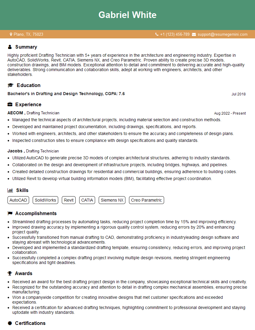
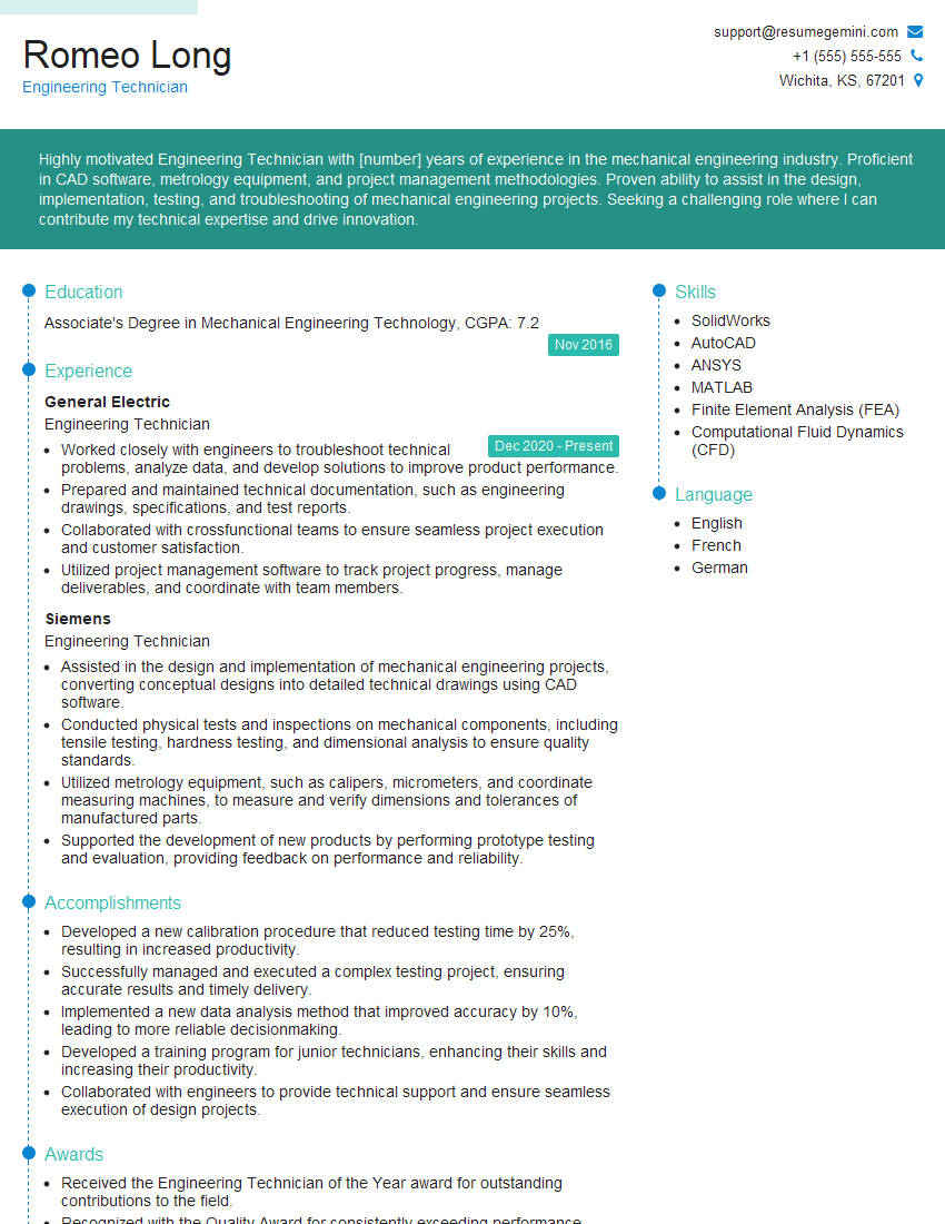
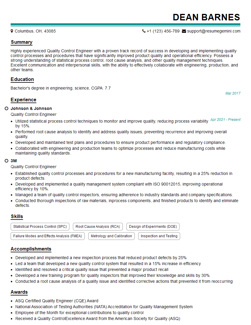
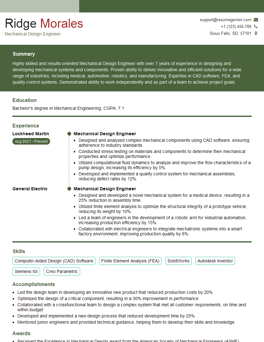
Mastering Mechanical Drawings and Specifications is crucial for career advancement in engineering and related fields. A strong understanding of these concepts is essential for effective communication with colleagues, successful project execution, and continuous professional development. To significantly boost your job prospects, creating an ATS-friendly resume is key. ResumeGemini is a trusted resource that can help you build a professional and impactful resume tailored to your skills and experience. Examples of resumes tailored to Mechanical Drawings and Specifications expertise are available to guide you through the process.
Explore more articles
Users Rating of Our Blogs
Share Your Experience
We value your feedback! Please rate our content and share your thoughts (optional).
What Readers Say About Our Blog
Hello,
We found issues with your domain’s email setup that may be sending your messages to spam or blocking them completely. InboxShield Mini shows you how to fix it in minutes — no tech skills required.
Scan your domain now for details: https://inboxshield-mini.com/
— Adam @ InboxShield Mini
Reply STOP to unsubscribe
Hi, are you owner of interviewgemini.com? What if I told you I could help you find extra time in your schedule, reconnect with leads you didn’t even realize you missed, and bring in more “I want to work with you” conversations, without increasing your ad spend or hiring a full-time employee?
All with a flexible, budget-friendly service that could easily pay for itself. Sounds good?
Would it be nice to jump on a quick 10-minute call so I can show you exactly how we make this work?
Best,
Hapei
Marketing Director
Hey, I know you’re the owner of interviewgemini.com. I’ll be quick.
Fundraising for your business is tough and time-consuming. We make it easier by guaranteeing two private investor meetings each month, for six months. No demos, no pitch events – just direct introductions to active investors matched to your startup.
If youR17;re raising, this could help you build real momentum. Want me to send more info?
Hi, I represent an SEO company that specialises in getting you AI citations and higher rankings on Google. I’d like to offer you a 100% free SEO audit for your website. Would you be interested?
Hi, I represent an SEO company that specialises in getting you AI citations and higher rankings on Google. I’d like to offer you a 100% free SEO audit for your website. Would you be interested?
good


