Every successful interview starts with knowing what to expect. In this blog, we’ll take you through the top Sheet Metal and Weldment Design interview questions, breaking them down with expert tips to help you deliver impactful answers. Step into your next interview fully prepared and ready to succeed.
Questions Asked in Sheet Metal and Weldment Design Interview
Q 1. Explain the difference between bending and forming in sheet metal.
Bending and forming are both processes used to shape sheet metal, but they differ in their approach and resulting geometry. Bending involves creating a sharp, localized change in the angle of the sheet metal, typically along a straight line. Think of folding a piece of paper – that’s bending. Forming, on the other hand, involves a more gradual and complex shape change across a larger area. It might involve stretching, compressing, or drawing the metal to create curves or contours. Imagine shaping clay – that’s more akin to forming. The key difference lies in the degree and nature of the deformation.
Example: Bending is used to create flanges on a box enclosure, while forming is used to create the curved surfaces of a car body panel. A simple U-bend is a bending operation while deep drawing a cylindrical cup from a flat sheet is a forming operation.
Q 2. Describe various sheet metal joining techniques.
Sheet metal joining techniques are crucial for assembling components. Several methods exist, each with its strengths and weaknesses:
- Welding: Joining through melting and fusing the metal. This offers high strength but can introduce heat distortion. Examples include spot welding, MIG welding, and TIG welding.
- Riveting: Using fasteners to mechanically join sheets. Relatively simple but may not be as strong as welding, especially in terms of fatigue resistance.
- Bolting/Screwing: Similar to riveting, but with removable fasteners. Offers flexibility for maintenance but requires pre-drilled holes and may introduce stress concentrations.
- Adhesives: Bonding with specialized glues. Suitable for lightweight applications but may have limitations in strength and temperature resistance.
- Crimping/Seaming: Interlocking edges without added fasteners, often done mechanically. Creates a strong, aesthetically pleasing joint, particularly for enclosures.
- Clinching: A mechanical joining technique that forms a mechanical interlock between two sheet metal parts without the addition of fasteners. Commonly used in automotive parts.
The choice depends on factors like strength requirements, cost, aesthetics, and assembly speed.
Q 3. What are the common types of welds and their applications?
Many weld types exist, each suitable for different applications. The most common include:
- Gas Metal Arc Welding (GMAW) or MIG Welding: Uses a continuously fed consumable wire electrode and shielding gas. Fast, versatile, and widely used in various applications, including automotive manufacturing and fabrication.
- Gas Tungsten Arc Welding (GTAW) or TIG Welding: Uses a non-consumable tungsten electrode and shielding gas. Produces high-quality welds with excellent penetration and control, suitable for thin sheet metal or critical applications.
- Shielded Metal Arc Welding (SMAW) or Stick Welding: Uses a consumable electrode coated with flux. Relatively simple and portable, often used in field applications but has lower quality compared to TIG or MIG.
- Spot Welding: Used to join overlapping sheets with a localized weld. High-speed and efficient for repetitive tasks in manufacturing, common in car body assembly.
- Resistance Welding: A broad category including spot welding, seam welding, and projection welding, utilizing the heat generated by resistance between two pieces of metal under pressure.
The selection depends on material thickness, weld strength requirements, joint geometry, and accessibility.
Q 4. How do you select appropriate materials for sheet metal and weldment applications?
Material selection is critical for both sheet metal and weldment design. Factors to consider include:
- Strength: The material must be strong enough to withstand anticipated loads and stresses.
- Formability: The material should be easily shaped without cracking or tearing during bending and forming operations.
- Weldability: The material must form strong and reliable welds with the chosen welding process.
- Corrosion Resistance: In many applications, resistance to rust and other forms of corrosion is essential.
- Cost: Balancing material properties with budget constraints is vital.
- Finish and Appearance: Depending on the application, the material’s surface finish and visual appearance may be important.
Example: Stainless steel is often chosen for its corrosion resistance in outdoor applications, while aluminum is preferred for its lightweight properties in aerospace designs. Mild steel is widely used for its balance of strength and cost-effectiveness.
Q 5. Explain the importance of tolerances in sheet metal and weldment design.
Tolerances define the acceptable variations in dimensions and geometry. Tight tolerances are crucial for proper fit and function in sheet metal and weldment assemblies. Inaccurate dimensions can lead to interference, gaps, or even structural failure. They impact manufacturing cost and complexity, as tighter tolerances often require more precise manufacturing techniques and increased inspection.
Example: If a hole is supposed to be 10mm in diameter, a tolerance of ±0.1mm indicates that the acceptable range is 9.9mm to 10.1mm. Exceeding this tolerance could prevent a bolt from fitting correctly.
Furthermore, weld tolerances specify acceptable variations in weld bead size, penetration depth, and joint geometry, which are essential to ensuring the structural soundness of the weldment.
Q 6. What are the common CAD software used for sheet metal design?
Several CAD software packages are specifically designed for sheet metal and weldment design. Popular choices include:
- Autodesk Inventor: A powerful and versatile software with advanced sheet metal and weldment modules. Offers features for automated flat pattern generation and weldment simulation.
- SolidWorks: Another industry-standard software with robust sheet metal and weldment capabilities. Includes tools for design automation and advanced analysis.
- CATIA: A high-end CAD software favored by large companies in aerospace and automotive industries; offers very advanced capabilities.
- Creo Parametric: A comprehensive CAD solution with sheet metal and weldment features suited for complex designs.
The choice depends on factors like project complexity, budget, and user familiarity.
Q 7. How do you ensure the structural integrity of a weldment?
Ensuring the structural integrity of a weldment involves several steps:
- Proper Joint Design: Selecting appropriate joint configurations (e.g., butt, lap, T-joint) based on load requirements and weldability.
- Material Selection: Choosing compatible materials with sufficient strength and weldability.
- Welding Process Selection: Choosing the appropriate welding process to achieve the required weld quality and penetration.
- Weld Inspection: Employing non-destructive testing methods like visual inspection, radiography, or ultrasonic testing to detect defects.
- Finite Element Analysis (FEA): Simulating the weldment’s behavior under load to assess stress concentrations and potential failure points. This is particularly crucial for complex structures.
- Proper Welding Procedures: Adhering to standardized welding procedures to ensure consistent and high-quality welds. This often includes pre-heat and post-weld heat treatments for certain materials.
Ignoring any of these steps can compromise the weldment’s integrity, potentially leading to catastrophic failure.
Q 8. Describe your experience with Finite Element Analysis (FEA) in weldment design.
Finite Element Analysis (FEA) is crucial in weldment design for predicting stress, strain, and deflection under various loading conditions. It allows us to virtually test a design before physical prototyping, saving time and resources. In my experience, I’ve used FEA extensively to analyze weld joints subjected to tensile, shear, bending, and fatigue loads. For example, I worked on a project involving a complex robotic arm. Using ANSYS, I modeled the arm’s weldments, applying loads simulating the arm’s operational movements. The FEA results highlighted stress concentrations around specific welds, prompting design modifications like fillet radius increases or weld reinforcement to mitigate potential failure points. This process ensures the weldment can withstand operational stresses without cracking or permanent deformation. I also incorporate FEA into my workflow to optimize weld bead geometry for improved strength and reduced weight, always considering factors like the welding process used (e.g., MIG, TIG) in the FEA model for realistic results.
Q 9. Explain different types of sheet metal gauges and their implications.
Sheet metal gauge refers to the thickness of the sheet metal. The lower the gauge number, the thicker the metal. For example, a 16-gauge sheet is thicker than an 18-gauge sheet. This has significant implications for design and manufacturing. Thicker gauges (lower numbers) are stronger and more rigid but more expensive and difficult to bend. Thinner gauges (higher numbers) are easier to form and cheaper but less durable and more prone to damage. The choice of gauge is a critical design decision based on the required strength, formability, cost, and the intended application. For instance, a car body panel might use a relatively thin gauge for ease of forming complex curves, while a structural component like a chassis member would need a much thicker gauge for strength and safety.
Q 10. How do you handle complex geometries in sheet metal design?
Handling complex geometries in sheet metal design often requires a combination of techniques and software capabilities. First, careful consideration of the unfolding process is crucial to avoid creating impossible-to-manufacture shapes. I frequently utilize specialized CAD software with sheet metal modules, such as SolidWorks or Autodesk Inventor, which offer tools for creating bend reliefs, flanges, and other features necessary for proper unfolding. For very intricate designs, I might employ techniques like splitting the part into simpler sections that are then assembled, or utilize advanced surfacing tools to create smooth transitions between complex curves. Furthermore, understanding the limitations of different sheet metal forming processes, such as stamping or bending, is paramount in achieving manufacturability. I often consult with manufacturing engineers early in the design process to ensure the feasibility of my design.
Q 11. What are the considerations for designing for manufacturability in sheet metal?
Designing for manufacturability in sheet metal involves considering several key factors to optimize the production process and minimize costs. These include:
- Bend Radii: Ensuring sufficient bend radii to prevent cracking or tearing during forming. Minimum bend radii are dictated by material thickness and the bending process used.
- Material Selection: Choosing appropriate sheet metal material based on strength, formability, and cost considerations.
- Tooling Considerations: Understanding the tooling required for various forming processes and designing parts that minimize tooling complexity and cost.
- Feature Placement: Strategically locating features to minimize material waste and simplify the forming process. Things like holes and cutouts should be placed where they won’t interfere with bends.
- Draft Angles: Incorporating draft angles on features to allow for easy part removal from tooling.
- Tolerances: Specifying realistic tolerances to account for variations in the manufacturing process.
Q 12. Explain the concept of springback in sheet metal forming.
Springback is the elastic recovery of sheet metal after it has been deformed. Imagine bending a paperclip – when you release the force, it partially springs back to its original shape. This phenomenon is significant in sheet metal forming because it can lead to dimensional inaccuracies. The degree of springback depends on factors such as material properties (Young’s modulus and yield strength), the amount of deformation, and the forming process. To compensate for springback, I typically utilize specialized software that simulates the process and predicts the final shape. This allows me to adjust the tooling or forming parameters to achieve the desired final dimensions. This often involves iterative simulations and adjustments, or the use of pre-bending techniques to counteract the springback effect.
Q 13. How do you address potential issues like warping or distortion during welding?
Warping and distortion during welding are common problems stemming from the heat input during the welding process. Several strategies can mitigate these issues:
- Preheating: Heating the workpiece prior to welding can reduce thermal gradients and minimize distortion.
- Welding Sequence: Carefully planning the welding sequence to balance heat input and minimize residual stresses.
- Fixture Design: Using fixtures to constrain the workpiece during welding and prevent distortion.
- Post-Weld Heat Treatment: Applying a controlled heat treatment after welding to relieve residual stresses and improve dimensional stability.
- Weld Bead Geometry Control: Optimizing weld bead geometry (e.g., using smaller beads or multiple passes) to minimize distortion.
Q 14. What are common weld defects and how are they detected?
Common weld defects include:
- Porosity: Small gas pockets in the weld metal, reducing strength.
- Cracks: Fractures in the weld metal, significantly weakening the joint.
- Incomplete Penetration: Weld metal failing to fully fuse with the base material.
- Undercutting: A groove melted into the base material adjacent to the weld.
- Lack of Fusion: Insufficient bonding between weld metal and base material.
- Visual Inspection: Simple check for obvious surface defects.
- Radiographic Testing (RT): X-rays or gamma rays are used to detect internal defects like porosity and cracks.
- Ultrasonic Testing (UT): High-frequency sound waves are used to detect internal flaws.
- Dye Penetrant Inspection (DPI): A liquid dye is used to highlight surface cracks.
Q 15. Describe your experience with different welding processes (MIG, TIG, etc.).
My experience encompasses a wide range of welding processes, primarily MIG (Metal Inert Gas) and TIG (Tungsten Inert Gas), but also includes exposure to SMAW (Shielded Metal Arc Welding) and spot welding. MIG welding, known for its speed and ease of use, is my go-to for high-volume production runs requiring strong, relatively fast welds. I’ve extensively used it on sheet metal components, achieving consistent results in joining various thicknesses of steel and aluminum. TIG welding, on the other hand, allows for incredibly precise control and clean welds, ideal for applications needing aesthetic appeal or working with thin gauge materials where heat control is critical. I’ve employed TIG welding in projects demanding intricate joins and high-quality surface finishes. My experience with SMAW is mostly in maintenance and repair scenarios, while spot welding knowledge comes from working with automated systems in high-volume production. I understand the nuances of each process – selecting the appropriate one depends heavily on material type, joint design, required weld quality, and production volume.
For instance, on a recent project involving a complex chassis assembly, we opted for MIG welding for the majority of the seams due to the high production volume required. However, for the critical suspension mounting points, requiring extreme precision and high strength, TIG welding was preferred due to the ability to precisely control heat input and ensure flawless penetration.
Career Expert Tips:
- Ace those interviews! Prepare effectively by reviewing the Top 50 Most Common Interview Questions on ResumeGemini.
- Navigate your job search with confidence! Explore a wide range of Career Tips on ResumeGemini. Learn about common challenges and recommendations to overcome them.
- Craft the perfect resume! Master the Art of Resume Writing with ResumeGemini’s guide. Showcase your unique qualifications and achievements effectively.
- Don’t miss out on holiday savings! Build your dream resume with ResumeGemini’s ATS optimized templates.
Q 16. How do you create detailed drawings and specifications for sheet metal parts?
Creating detailed drawings and specifications for sheet metal parts requires a meticulous approach and a thorough understanding of manufacturing processes. I typically start by using CAD software (SolidWorks, AutoCAD, etc.) to model the part in 3D, ensuring accurate dimensions and tolerances. The model then forms the basis for creating detailed 2D drawings which include critical information like:
- Views: Multiple orthographic views (front, top, side) to depict the part’s geometry completely.
- Dimensions: Precise dimensions and tolerances, following standards like ASME Y14.5.
- Material Specifications: Clearly stating the material type, grade, and thickness.
- Bend Radii and Break Lines: Essential details for sheet metal bending operations.
- Hole Sizes and Locations: Precise location and dimensions of all holes, including tolerances.
- Surface Finish: Specifying the required surface roughness.
- Bill of Materials (BOM): Listing all materials and fasteners needed for assembly.
- Welding Symbols (if applicable): Defining the type of weld, its location, and specifications.
I always strive to create clear and concise drawings to minimize ambiguity and prevent manufacturing errors. The creation of detail drawings is closely linked to Design for Manufacturing principles, ensuring the design is manufacturable and cost effective. For example, I avoid using unnecessary features, simplify geometry wherever possible, and carefully consider the tooling required for fabrication.
Q 17. What are the safety precautions you take when working with sheet metal and welding equipment?
Safety is paramount in my work. When handling sheet metal and welding equipment, I adhere to stringent safety protocols. These include:
- Personal Protective Equipment (PPE): Always wearing appropriate PPE, including safety glasses, welding helmet with appropriate shade lens (depending on the welding process), heat-resistant gloves, and sturdy closed-toe shoes. For specific tasks, I’ll add things like hearing protection and a respirator.
- Workplace Safety: Maintaining a clean and organized workspace free from clutter and tripping hazards. Ensuring proper ventilation is crucial for welding operations, removing fumes and potential hazardous gases.
- Equipment Maintenance: Regularly inspecting welding equipment (MIG guns, TIG torches, etc.) for damage, and ensuring that they are properly grounded and maintained according to manufacturer specifications. I know that damaged tools can be extremely dangerous and I never compromise on this step.
- Fire Safety: Having fire extinguishers readily available and being aware of fire hazards associated with welding, including using fire-resistant blankets to protect surrounding materials.
- Material Handling: Using appropriate lifting techniques and equipment for handling heavy sheet metal. Never lifting beyond my capabilities.
- Emergency Procedures: Being familiar with emergency procedures in case of accidents or injuries. This includes knowing where safety showers and eye wash stations are located.
Regular safety training is essential to stay updated on best practices and new technologies. I always advocate for proactive safety measures rather than reactive ones.
Q 18. Explain the importance of proper material selection for weldability.
Proper material selection is crucial for weldability because different materials exhibit varying responses to welding processes. Factors like melting point, thermal conductivity, and susceptibility to cracking significantly impact weld quality and strength. Selecting incompatible materials can result in brittle welds, porosity, cracking, and overall structural failure. For example, using dissimilar metals without proper pre- and post-weld treatment can cause intermetallic compounds forming brittle layers in the weld zone.
Consider steel alloys. High-carbon steels are notoriously difficult to weld due to their high hardness and tendency to crack. Low-carbon steels, on the other hand, weld relatively easily. Aluminum requires special welding techniques and filler materials due to its high thermal conductivity and tendency to oxidize. Stainless steels demand careful control of heat input to prevent undesirable metallurgical changes. Understanding these material characteristics is paramount in selecting appropriate welding processes and filler materials, ultimately ensuring a durable and reliable weld.
In practice, I always consult material data sheets and welding handbooks to determine the best material choices for a specific application. For instance, if a design requires high strength and corrosion resistance, I might select a high-strength low-alloy steel but would carefully consider the weldability challenges and design accordingly (perhaps using preheating and proper post-weld heat treatment).
Q 19. How do you manage design changes and revisions in a collaborative environment?
Managing design changes and revisions in a collaborative environment necessitates a structured and organized approach. I typically utilize a version control system (like SolidWorks PDM or similar) to track all changes and revisions to the design. This system allows for controlled access to the design files, ensuring that everyone works with the most up-to-date version.
We frequently use design review meetings with stakeholders (engineering, manufacturing, procurement) to discuss and approve changes. Minutes from these meetings are meticulously documented, along with a change request log that outlines the reason for the change, its impact on the design, and its implications for manufacturing and cost. A revision numbering system is implemented to clearly identify each version of the design. This system makes tracing changes simple, allowing us to easily revert to previous versions if necessary. Clear communication is crucial, and I ensure everyone involved is informed of the design changes and their implications. Regular updates keep everyone on the same page.
Q 20. Describe your experience with Design for Manufacturing (DFM) principles.
Design for Manufacturing (DFM) principles are integral to my design process. DFM focuses on designing products that are easy and cost-effective to manufacture. I apply several key DFM principles:
- Simplify Geometry: Avoiding complex shapes and features that require specialized or expensive tooling.
- Standard Components: Utilizing standard parts and fasteners whenever possible to reduce costs and lead times.
- Minimize Machining: Designing parts to minimize the need for expensive machining operations.
- Consider Material Selection: Choosing readily available and easily weldable materials.
- Optimize for Manufacturing Processes: Designing parts that are easily fabricated using sheet metal bending, punching, and welding techniques.
- Assembly Considerations: Designing parts that are easily assembled, minimizing the number of fasteners and assembly steps.
A recent project highlighted the importance of DFM. The initial design had complex curves requiring custom tooling. By simplifying the geometry slightly, we were able to utilize standard bending processes, significantly reducing tooling costs and manufacturing lead time, without compromising on functionality. DFM is not about compromising functionality but about designing smartly for efficient production.
Q 21. How do you optimize a design for cost-effectiveness in sheet metal and weldment fabrication?
Optimizing a design for cost-effectiveness in sheet metal and weldment fabrication involves a multi-faceted approach, combining design considerations with manufacturing expertise. I focus on these key areas:
- Material Selection: Choosing cost-effective materials without sacrificing required properties. Using cheaper materials where permissible and suitable will obviously save money.
- Part Consolidation: Combining multiple parts into fewer, larger components to reduce assembly costs and labor.
- Simplify Geometry: Avoiding complex geometries that require expensive tooling or specialized processes. Standard features require simpler and less expensive manufacturing processes.
- Standard Parts and Fasteners: Utilizing readily available and standard components and fasteners minimizes costs and lead times.
- Efficient Joint Design: Designing simple, easily weldable joints that minimize weld time and material waste. Butt welds are cheaper than lap welds, for example.
- Minimize Material Usage: Optimizing the design to minimize the amount of sheet metal needed without sacrificing structural integrity.
- Collaboration with Manufacturing: Close collaboration with the manufacturing team helps identify potential cost savings early in the design process. Working closely with the manufacturing team is absolutely essential to identify potential problems before they become costly.
For example, by using nesting software to optimize the layout of parts on a sheet metal blank, we can significantly reduce material waste. Through this integration of design and manufacturing expertise, substantial cost savings can be achieved without compromising the integrity or quality of the final product.
Q 22. How do you ensure the quality and consistency of welds?
Ensuring consistent, high-quality welds involves a multi-faceted approach encompassing welder qualification, proper weld procedure specification (WPS), and rigorous inspection. It’s like baking a cake – you need the right ingredients (materials and welders), the right recipe (WPS), and careful monitoring (inspection) to get a consistently perfect result.
- Welder Qualification: Welders must be qualified to the relevant welding codes (e.g., ASME Section IX, AWS D1.1) through rigorous testing demonstrating their proficiency in specific welding processes and materials. This ensures consistent weld quality regardless of the welder.
- Weld Procedure Specification (WPS): A WPS is a detailed document specifying every aspect of the welding process, including the materials, welding parameters (voltage, amperage, travel speed), pre- and post-weld heat treatments, and cleaning procedures. Think of it as a detailed recipe guaranteeing reproducibility. Any deviation requires a procedure qualification record (PQR).
- Non-Destructive Testing (NDT): Methods like radiographic testing (RT), ultrasonic testing (UT), and visual inspection are used to detect internal and external weld defects. Regular NDT throughout the welding process identifies problems early, allowing for corrections and preventing costly rework.
- Process Monitoring and Control: Monitoring parameters like amperage, voltage, and travel speed during welding ensures adherence to the WPS. Modern welding equipment often provides real-time data logging capabilities for traceability and analysis.
By implementing these procedures, we minimize variability and ensure consistent, high-quality welds, reducing scrap and increasing efficiency.
Q 23. What are your preferred methods for creating and managing bill of materials (BOMs)?
Effective BOM management is crucial for efficient manufacturing. My preferred methods leverage the strengths of both software and structured processes.
- Software Solutions: I utilize enterprise resource planning (ERP) systems or dedicated CAD/CAM software with integrated BOM management capabilities. These systems streamline the process by automatically generating BOMs based on the design, linking components to drawings and specifications. Examples include Autodesk Inventor, SolidWorks, and ERP systems like SAP.
- Structured Data Management: Beyond software, I maintain a structured approach, clearly defining component numbers, descriptions, materials, quantities, and suppliers. This clarity is essential for accurate costing, procurement, and inventory management. A well-defined structure also enhances collaboration with the manufacturing team.
- Regular BOM Reviews: Periodic reviews, particularly during design changes, are vital for keeping the BOM accurate and up-to-date. This prevents discrepancies between the design and the actual components used.
- Version Control: Tracking different BOM versions through software or a document control system is crucial for traceability and for managing revisions throughout the product lifecycle. This ensures that the correct BOM is always used.
This combined approach to BOM creation and management ensures accuracy, traceability, and efficiency across all stages of the product lifecycle.
Q 24. Describe your experience with different types of sheet metal finishes.
Sheet metal finishes significantly impact a product’s aesthetics, durability, and functionality. My experience spans a range of finishes, each chosen for its specific properties.
- Powder Coating: Offers excellent durability, resistance to corrosion, and a wide variety of colors and textures. Ideal for outdoor applications or environments with harsh conditions.
- Painting: Provides a wide range of colors and finishes, but offers less durability than powder coating. Appropriate for indoor applications or where cost is a primary concern.
- Electroplating (e.g., Chrome, Nickel): Offers excellent corrosion resistance and a highly polished finish. Often used for decorative or high-durability applications but can be expensive.
- Anodizing (for Aluminum): Provides excellent corrosion resistance and a durable finish for aluminum substrates. Offers a variety of colors and finishes.
- Passivation (for Stainless Steel): A chemical treatment that enhances the corrosion resistance of stainless steel by creating a protective oxide layer.
The selection of the appropriate finish depends on the application’s requirements – balancing cost, durability, aesthetics, and environmental considerations.
Q 25. How do you use GD&T (Geometric Dimensioning and Tolerancing) in sheet metal design?
GD&T is indispensable in sheet metal design, ensuring dimensional accuracy and interchangeability. It moves beyond simple tolerance specifications to define the geometric relationship between features.
- Feature Control Frames (FCFs): FCFs are used to specify tolerances for features like flatness, straightness, parallelism, perpendicularity, and position. For instance, an FCF might specify the allowable deviation from flatness for a sheet metal panel, preventing warping and ensuring proper fit.
- Datum References: GD&T uses datums (reference features) to define the coordinate system for measurements. This is particularly important in sheet metal where accurate alignment between parts is critical. For example, you might define a datum on a hole to ensure consistent positioning of other features.
- Tolerance Stack-up Analysis: GD&T enables a thorough tolerance stack-up analysis, predicting the potential cumulative variations of dimensions throughout the assembly. This prevents unexpected interference or clearance issues.
By incorporating GD&T in my designs, I create more robust and reliable sheet metal components, minimizing the risk of manufacturing issues and ensuring that components fit correctly in the final assembly.
Q 26. Explain your experience with creating and interpreting weld symbols.
Weld symbols are a standardized way of communicating the welding requirements on engineering drawings. Understanding and creating them is essential for unambiguous communication between designers and fabricators. They are like a concise instruction manual for the welder.
- Basic Symbol Elements: A weld symbol contains several elements: a reference line, an arrow, a basic weld symbol (indicating the weld type), supplementary symbols (indicating weld size, process, etc.), and dimensions.
- Reference Line: A horizontal line connecting the arrow to the symbol. The arrow points towards the part being welded.
- Arrow Side vs. Other Side: Symbols placed on the arrow side indicate requirements for that side of the joint; symbols placed above the reference line indicate requirements for the opposite side.
- Supplementary Symbols: These symbols indicate details like the weld type (e.g., fillet, groove, spot), the welding process (e.g., GMAW, SMAW), and dimensions (length, size).
For example, a weld symbol showing a fillet weld on the arrow side and a groove weld on the other side would convey precisely how each weld should be executed. I ensure drawings are clear and complete to prevent misinterpretations and ensure the welding process meets specifications.
Q 27. How do you conduct root cause analysis for manufacturing defects in sheet metal or weldments?
Root cause analysis (RCA) for manufacturing defects is crucial for preventing recurrence. My approach follows a structured methodology, akin to detective work.
- Data Collection: Gather comprehensive data, including defect type, location, frequency, and any relevant process parameters. Visual inspection, measurements, and NDT are essential.
- 5 Whys Technique: This iterative questioning technique helps to drill down to the underlying cause of the defect. By repeatedly asking ‘why’ after each answer, we gradually reveal the root problem. For example, a warped panel might lead to questions: Why is it warped? (Uneven heating during welding). Why was the heating uneven? (Faulty welding equipment calibration).
- Fishbone Diagram (Ishikawa Diagram): This visual tool helps to brainstorm potential causes, categorized into factors like materials, equipment, processes, and people. It helps organize ideas and identify possible root causes.
- Corrective Actions: Once the root cause is identified, implementing corrective actions is critical. These actions can range from process improvements (e.g., better machine calibration) to personnel training (e.g., enhanced welder training).
Documenting the entire RCA process, including findings and corrective actions, is crucial for preventing future occurrences of the same defect. Continuous improvement relies on learning from past mistakes.
Q 28. Describe a challenging sheet metal or weldment design project you worked on and how you overcame the challenges.
One challenging project involved designing a complex sheet metal enclosure for a high-precision electronic instrument. The design required extremely tight tolerances, intricate cutouts, and robust shielding against electromagnetic interference (EMI).
- Challenge 1: Tight Tolerances: Meeting the tight tolerances required precise design and manufacturing processes. This involved careful consideration of material properties, manufacturing limitations, and the use of advanced GD&T techniques.
- Challenge 2: Complex Cutouts: The intricate cutouts required sophisticated tooling and careful part nesting to minimize material waste and ensure accurate dimensions. This necessitated close collaboration with the manufacturing team.
- Challenge 3: EMI Shielding: Achieving effective EMI shielding required specific material selections and design considerations. Finite element analysis (FEA) simulations were used to assess the effectiveness of the proposed design.
I overcame these challenges through a combination of careful design, thorough simulation, and close collaboration with manufacturing. The design used features like formed ribs for rigidity, and specific materials to address the EMI shielding. We also developed a detailed manufacturing plan, including detailed tooling designs and process specifications. The final product met all requirements and performed flawlessly, demonstrating the importance of a well-integrated approach.
Key Topics to Learn for Sheet Metal and Weldment Design Interview
- Sheet Metal Design Fundamentals: Understanding material properties (gauge, yield strength, ductility), bend allowances, springback, and different forming processes (punching, bending, stamping).
- Weldment Design Principles: Selecting appropriate welding processes (MIG, TIG, spot welding) based on material and application, understanding weld symbols and their implications, designing for weldability and minimizing stress concentrations.
- CAD Software Proficiency: Demonstrating practical experience with industry-standard software like SolidWorks, AutoCAD, or Inventor for creating and modifying 3D models of sheet metal and weldments.
- Geometric Dimensioning and Tolerancing (GD&T): Applying GD&T principles to ensure precise manufacturing and assembly of sheet metal and weldment components. Understanding how tolerances affect design and manufacturing costs.
- Finite Element Analysis (FEA) (Optional): Familiarity with FEA software and its application in analyzing stress, strain, and deformation in sheet metal and weldment designs.
- Manufacturing Processes and Material Selection: Understanding the practical aspects of sheet metal fabrication and welding, including tooling, processes, and material selection considerations for cost-effectiveness and performance.
- Design for Manufacturing (DFM): Optimizing designs for efficient manufacturing, minimizing waste, and reducing production costs. Considering factors like manufacturability, assembly, and cost.
- Problem-solving and Troubleshooting: Demonstrating your ability to identify and resolve design challenges related to sheet metal forming, welding, and assembly. Showcasing practical experience in troubleshooting manufacturing issues.
Next Steps
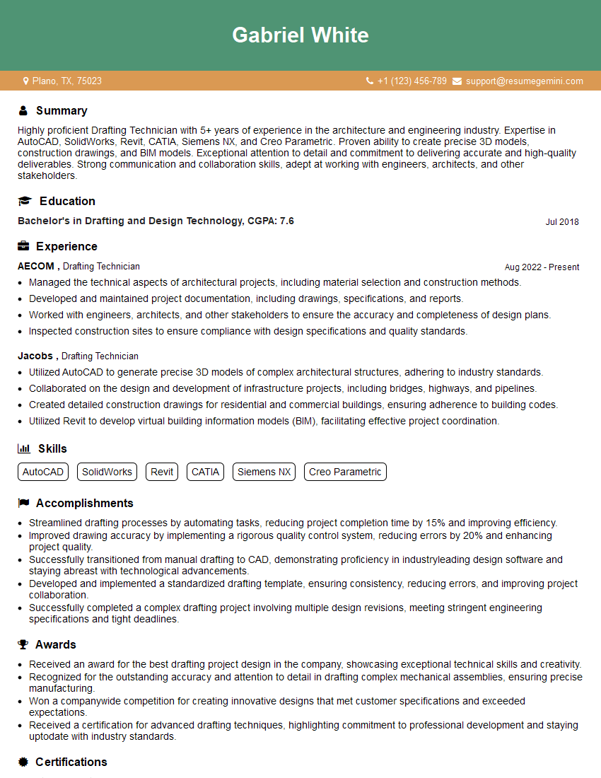
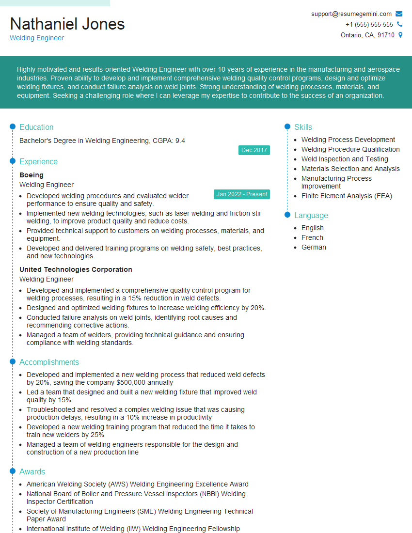
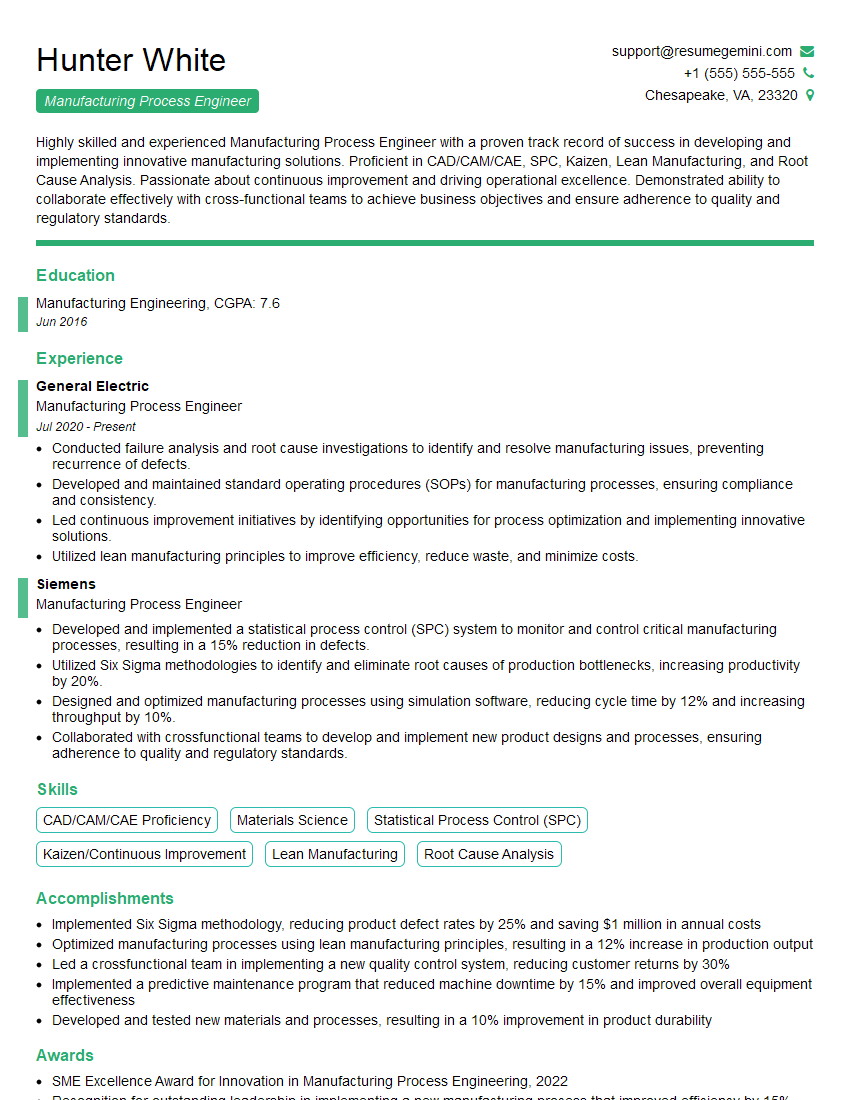
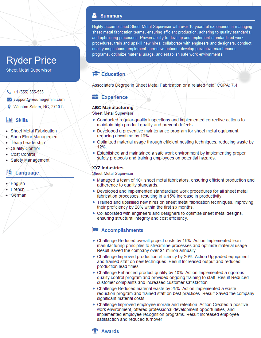
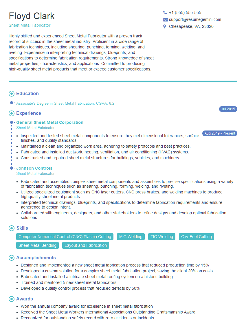
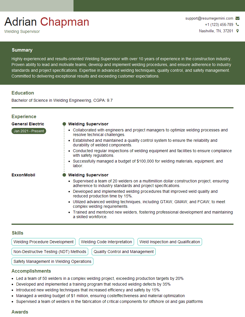
Mastering Sheet Metal and Weldment Design opens doors to exciting career opportunities in manufacturing, aerospace, automotive, and many other industries. A strong understanding of these principles is highly sought after and will significantly boost your earning potential. To maximize your job prospects, create an ATS-friendly resume that highlights your skills and experience effectively. ResumeGemini is a trusted resource that can help you build a professional and impactful resume tailored to the specific requirements of Sheet Metal and Weldment Design roles. Examples of resumes tailored to this field are available to guide you. Take the next step towards your dream career today!
Explore more articles
Users Rating of Our Blogs
Share Your Experience
We value your feedback! Please rate our content and share your thoughts (optional).
What Readers Say About Our Blog
Hi, I represent an SEO company that specialises in getting you AI citations and higher rankings on Google. I’d like to offer you a 100% free SEO audit for your website. Would you be interested?
good
