Interviews are opportunities to demonstrate your expertise, and this guide is here to help you shine. Explore the essential Test and Measurement Equipment Operation interview questions that employers frequently ask, paired with strategies for crafting responses that set you apart from the competition.
Questions Asked in Test and Measurement Equipment Operation Interview
Q 1. Explain the difference between accuracy and precision in measurement.
Accuracy and precision are two crucial aspects of measurement, often confused but distinctly different. Accuracy refers to how close a measurement is to the true value. Think of it like hitting the bullseye on a dartboard – a highly accurate measurement lands very close to the center. Precision, on the other hand, refers to how close repeated measurements are to each other. This is like consistently hitting the same spot on the dartboard, even if that spot isn’t the bullseye. You can have high precision with low accuracy (consistently missing the bullseye by the same amount), high accuracy with low precision (randomly hitting near the bullseye but not consistently), or ideally, both high accuracy and high precision (consistently hitting the bullseye).
Example: Imagine measuring the length of a table. A ruler with poor calibration might give consistently inaccurate readings (low accuracy), but those readings might be very close to each other (high precision). A ruler that gives varied readings (low precision) might occasionally happen to be close to the true value (high accuracy).
Q 2. Describe your experience with different types of oscilloscopes (e.g., digital, analog).
My experience encompasses both analog and digital oscilloscopes. I’ve worked extensively with analog oscilloscopes, appreciating their ability to provide a real-time visual representation of waveforms. This is particularly useful for observing transient events and understanding the overall signal shape. However, their limitations in measurement precision and the absence of automated analysis tools led me to adopt digital oscilloscopes as my primary tool. Digital oscilloscopes offer superior precision, extensive measurement capabilities (like automated rise/fall time calculations), data storage, and advanced triggering options. I’ve used various models, including those with mixed-signal capabilities (allowing simultaneous analysis of analog and digital signals), and those equipped with advanced features like deep memory for capturing long waveforms or high bandwidth for analyzing fast signals.
Example: In one project, I used a digital oscilloscope with a high sampling rate to analyze high-frequency clock signals in a circuit design. The precise measurements obtained were crucial for timing analysis and debugging.
Q 3. How do you calibrate a multimeter?
Multimeter calibration depends on the specific model and its features. Generally, it’s a multi-step process that requires specialized equipment and a careful approach. First, the multimeter should be checked for any physical damage. Then, a calibration standard, such as a precision voltage source, current source, or resistance standard (often traceable to national standards) is needed. The multimeter is then used to measure the known values provided by the calibration standard. The readings are compared to the known values, and if there are significant deviations (outside the specified tolerance), adjustments are made using internal calibration procedures (if available) or external calibration tools (often handled by a calibration laboratory).
Important Note: Attempting to calibrate a multimeter without proper training and equipment can result in damage to the instrument or inaccurate measurements. It is often best to send the multimeter to a certified calibration laboratory.
Q 4. What are common sources of error in test and measurement?
Common sources of error in test and measurement can be broadly classified into:
- Instrument Errors: These stem from limitations in the equipment itself, such as inaccuracy in calibration, noise, drift, and insufficient resolution.
- Environmental Errors: Temperature fluctuations, humidity, electromagnetic interference (EMI), and vibration can all affect measurement accuracy.
- Human Errors: Incorrect connections, misreading displays, parallax error (incorrect angle of observation), and improper instrument setup are common human-related errors.
- Test Setup Errors: Improper grounding, insufficient shielding, and loading effects (where the measuring instrument affects the circuit being measured) can introduce significant errors.
Example: A poorly shielded test setup might pick up ambient electromagnetic interference, leading to inaccurate voltage measurements. Improper grounding can cause false readings or even damage the instrument.
Q 5. Explain the concept of signal-to-noise ratio (SNR).
Signal-to-noise ratio (SNR) is a measure of the strength of a desired signal compared to the level of background noise. It’s typically expressed in decibels (dB). A higher SNR indicates a stronger signal relative to the noise, meaning the signal is easier to distinguish and measure accurately. Think of it as trying to hear a quiet conversation in a noisy room. A high SNR represents a clear conversation easily understood, while a low SNR signifies difficulty in hearing the conversation because of excessive background noise.
Formula: SNR (dB) = 10 * log10(Psignal / Pnoise), where Psignal and Pnoise are the power of the signal and noise respectively.
Practical Application: In communication systems, a high SNR is crucial for reliable data transmission. In audio recording, a high SNR results in cleaner and higher-fidelity audio.
Q 6. How do you troubleshoot a faulty measurement?
Troubleshooting a faulty measurement involves a systematic approach:
- Identify the discrepancy: What is the unexpected or inaccurate reading? Compare it to expected values or previous measurements.
- Check the instrument: Is the multimeter or oscilloscope calibrated? Are the leads in good condition? Check for any obvious signs of damage.
- Review the setup: Are the connections secure? Is the test setup properly grounded and shielded? Are there any loading effects impacting the measurement?
- Check environmental factors: Are there any sources of EMI or significant temperature fluctuations?
- Verify the signal source: Ensure the signal source is functioning correctly. Use alternative methods or instruments to verify the signal characteristics if possible.
- Isolate the problem: Use a process of elimination to pinpoint the cause of the faulty measurement.
Example: If a low voltage reading is suspected, one would check the multimeter’s calibration, the probe connections, and the circuit being measured, and rule out possible interference before concluding the actual voltage is indeed low.
Q 7. Describe your experience with data acquisition systems.
My experience with data acquisition (DAQ) systems is extensive. I’ve worked with various DAQ systems, ranging from simple, low-channel-count systems for basic measurements to sophisticated, multi-channel systems capable of acquiring high-speed, high-resolution data from multiple sensors. This includes both hardware and software aspects: selecting appropriate sensors, configuring DAQ hardware for optimal sampling rates and signal conditioning, and utilizing specialized software to process, analyze, and visualize the acquired data. This experience covers various applications, including environmental monitoring, vibration analysis, and industrial process control.
Example: In a project involving vibration analysis of a rotating machine, I used a DAQ system equipped with accelerometers to capture vibration data. The acquired data was then analyzed to detect potential bearing failures before they caused significant damage.
Q 8. What is the significance of traceability in calibration?
Traceability in calibration is crucial for ensuring the accuracy and reliability of measurement results. It’s essentially a chain of comparisons that links your measurement instrument’s calibration back to national or international standards. Imagine a family tree for your measurement – each branch shows how its accuracy is verified.
This is achieved through a series of calibrations, each traceable to a higher standard. For instance, your laboratory thermometer might be calibrated against a more accurate reference thermometer, which is itself calibrated against a national standard maintained by a metrology institute. This unbroken chain of comparisons establishes the validity of your measurements.
Without traceability, you can’t be confident in the accuracy of your measurements. A poorly calibrated instrument could lead to significant errors in manufacturing, research, or any field relying on precise measurements. Traceability ensures that if a problem arises, the source of error can be easily identified and corrected.
Q 9. Explain your experience using spectrum analyzers.
I have extensive experience using spectrum analyzers for various applications, including signal analysis, electromagnetic interference (EMI) testing, and radio frequency (RF) characterization. I’m proficient in operating both vector and scalar network analyzers from various manufacturers.
For example, during my work at [Previous Company Name], I used a Rohde & Schwarz FSW spectrum analyzer to analyze the spectral purity of a newly developed wireless communication system. We were able to identify spurious emissions and adjust the design to meet regulatory compliance requirements. This involved configuring the analyzer to display the desired frequency range, setting the resolution bandwidth, and using marker functions to accurately measure the power levels of specific signals. I also utilized its sweep functions to efficiently scan a wide frequency range and identify potential problems.
In another project, we used a spectrum analyzer to troubleshoot signal degradation in a satellite communication link. By analyzing the signal’s spectrum, we were able to pinpoint the source of the interference and resolve the issue. I’m comfortable with advanced features such as channel power measurements, occupied bandwidth measurements, and noise floor analysis.
Q 10. How do you ensure the safety of yourself and equipment during testing?
Safety is paramount in a test and measurement environment. My approach always prioritizes both personal safety and the protection of equipment. This begins with a thorough risk assessment before starting any test.
I always adhere to safety protocols including wearing appropriate personal protective equipment (PPE) such as safety glasses, gloves, and hearing protection, depending on the nature of the test and equipment. I’m familiar with various safety standards and regulations and always ensure proper grounding and bonding of equipment to prevent electrical shocks.
For high-voltage testing, I always employ safety interlocks and follow strict procedures to avoid any accidents. I regularly inspect equipment for damage or wear and tear and ensure that all safety features are functioning correctly. When working with potentially hazardous materials, I’ll follow established safety data sheets (SDS) and waste disposal procedures diligently. Proactive safety measures are a core part of my workflow.
Q 11. Describe your experience with automated test equipment (ATE).
My experience with automated test equipment (ATE) spans several years, working with various systems for both functional and in-circuit testing. I’m familiar with programming ATE systems using languages such as TestStand and LabVIEW.
In a previous role, I was responsible for developing and maintaining automated test routines for printed circuit boards (PCBs) using a Teradyne UltraFLEX system. This involved designing test sequences, writing test programs, and troubleshooting any failures. We implemented automated data logging and analysis to improve efficiency and identify trends in product defects.
My expertise extends to integrating ATE systems with other equipment, such as signal generators, power supplies, and oscilloscopes, to create comprehensive test setups. I’m capable of analyzing test results, identifying areas for improvement in the testing process, and maintaining the ATE systems to ensure consistent and reliable performance. I’m comfortable with the complexities of integrating different software and hardware components.
Q 12. What are your preferred methods for documenting test results?
My preferred methods for documenting test results emphasize clarity, accuracy, and traceability. I utilize a combination of digital and physical documentation.
Digital documentation primarily uses a laboratory information management system (LIMS) or a structured spreadsheet to store all data, including timestamps, instrument settings, and raw data. This ensures easy access and analysis of results. The system will typically include automated reports generated directly from the test data to minimize errors and save time.
Physical documentation involves maintaining a hard copy of key results and relevant calibration certificates. This is vital for traceability and regulatory compliance. I always ensure that all documentation is meticulously maintained, stored securely, and properly version-controlled. The goal is to create an easily auditable record of each test conducted.
Q 13. How familiar are you with different types of sensors?
I have a solid understanding of various sensor types and their applications, encompassing several domains like temperature, pressure, strain, light, and flow sensors. My experience covers both analog and digital sensors.
For example, I’ve worked extensively with thermocouples for high-temperature measurements, strain gauges for structural analysis, and photodiodes for optical power measurements. I understand the importance of sensor calibration, signal conditioning, and the limitations of each sensor type. I’m familiar with different sensor interfaces, such as analog voltage output, digital communication protocols like I2C and SPI, and fieldbus systems.
Choosing the right sensor involves considering factors like accuracy, precision, response time, and environmental compatibility. I’m capable of selecting and integrating sensors into various test setups, ensuring the accuracy and reliability of measurements. Understanding sensor limitations and potential sources of error is key to successful measurement.
Q 14. Explain your experience with statistical process control (SPC).
Statistical Process Control (SPC) is a crucial tool for monitoring and improving processes by identifying variations and trends in data. I’ve used SPC extensively for analyzing test data and identifying potential issues.
I have experience implementing control charts such as X-bar and R charts, C charts, and p-charts, depending on the type of data collected. These charts help to visualize process variability and detect any shifts or trends that may indicate a problem. I’m proficient in interpreting these charts and determining if process adjustments are necessary. This often involves calculating control limits and understanding the implications of exceeding those limits.
In a real-world scenario, I utilized SPC to monitor the yield of a semiconductor manufacturing process. By tracking key parameters and implementing control charts, we were able to identify and address root causes of defects and significantly improve the overall yield. This involved collaboration with other engineers and technicians to implement corrective actions and continuously improve the manufacturing process. Data-driven decision making was vital to this success.
Q 15. Describe your experience with different types of transducers.
Transducers are the crucial link between the physical world and our measurement systems. They convert a non-electrical physical quantity, like pressure, temperature, or displacement, into an electrical signal that we can measure and analyze. My experience spans a wide range of transducer types, including:
- Strain gauges: I’ve extensively used strain gauges for measuring strain and stress in materials, often integrated into load cells for weighing applications. For example, I’ve worked on projects involving the precise measurement of stress on aircraft components during simulated flight conditions.
- Thermocouples: These are essential for high-temperature measurements. I’ve used them in numerous applications, from monitoring furnace temperatures to testing the thermal performance of electronic components. One specific project involved characterizing the temperature profile inside a high-power LED lighting fixture.
- Piezoelectric transducers: These are excellent for measuring dynamic events like pressure fluctuations or vibrations. I’ve worked with piezoelectric accelerometers in vibration analysis of machinery, identifying resonance frequencies and potential failure points.
- Pressure transducers: From simple pressure gauges to sophisticated differential pressure sensors, I’ve used these to monitor everything from fluid pressures in pipelines to air pressure in aircraft cabins. Calibration and accuracy are paramount here, and I possess extensive experience in these areas.
- Displacement transducers: These include LVDTs (Linear Variable Differential Transformers) and capacitive sensors. I’ve applied these in precision measurement tasks, like verifying the dimensional accuracy of manufactured parts and monitoring the movement of robotic arms.
Understanding the operating principles, limitations, and calibration procedures of each type is critical for accurate measurements and reliable data acquisition. I always consider factors like sensitivity, linearity, and hysteresis when selecting and employing a transducer.
Career Expert Tips:
- Ace those interviews! Prepare effectively by reviewing the Top 50 Most Common Interview Questions on ResumeGemini.
- Navigate your job search with confidence! Explore a wide range of Career Tips on ResumeGemini. Learn about common challenges and recommendations to overcome them.
- Craft the perfect resume! Master the Art of Resume Writing with ResumeGemini’s guide. Showcase your unique qualifications and achievements effectively.
- Don’t miss out on holiday savings! Build your dream resume with ResumeGemini’s ATS optimized templates.
Q 16. How do you handle discrepancies between measured and expected values?
Discrepancies between measured and expected values are a routine occurrence in testing and measurement. My approach involves a systematic investigation, following these steps:
- Review the Measurement Setup: First, I meticulously check the entire setup – the transducer, cabling, instrumentation, and data acquisition system. Loose connections, faulty wiring, or incorrectly configured software can be common sources of error.
- Check Calibration: I verify the calibration status of all equipment involved. If the equipment is not calibrated, or the calibration is out of date, it can lead to significant errors. Recalibration, if necessary, is crucial.
- Consider Environmental Factors: Temperature, humidity, and ambient conditions can significantly influence measurements. I ensure that the testing environment is controlled and that environmental corrections are applied where necessary.
- Analyze the Data: I examine the data for anomalies, outliers, and patterns that could indicate a systematic error. Statistical analysis techniques can help identify trends and potential sources of discrepancies.
- Identify Potential Sources of Error: This is where deeper investigation is needed. Possibilities include transducer error, signal noise, data acquisition errors, or even incorrect assumptions in the expected value calculation.
- Document and Report: All findings, including corrective actions taken, are meticulously documented and reported. This is essential for maintaining traceability and ensuring the integrity of the test results.
For example, in one project involving the testing of a high-precision pressure sensor, a significant discrepancy was traced to an unnoticed air leak in the test fixture. Systematic troubleshooting, along with careful data analysis, allowed us to pinpoint the source of the error.
Q 17. What software packages are you proficient in for data analysis?
I’m proficient in several software packages crucial for data analysis in test and measurement:
- LabVIEW: My expertise in LabVIEW allows me to develop custom data acquisition and analysis systems, automate test procedures, and create sophisticated user interfaces. This includes designing applications for data logging, signal processing, and real-time data visualization.
- MATLAB: I use MATLAB extensively for advanced signal processing, statistical analysis, and data visualization. This often involves using toolboxes for signal processing, image processing, and control system design.
- Python (with relevant libraries): Python, especially with libraries like NumPy, SciPy, and Matplotlib, is an indispensable tool for data manipulation, analysis, and presentation. I leverage its versatility for automating tasks, performing complex calculations, and generating publication-quality figures.
- Microsoft Excel (advanced usage): While seemingly basic, my skills in Excel extend beyond basic spreadsheet operations. I utilize advanced functions for data analysis, including statistical analysis, data transformation, and charting.
My proficiency in these tools allows me to efficiently process large datasets, perform complex calculations, and generate meaningful reports and visualizations.
Q 18. How do you maintain and troubleshoot test equipment?
Maintaining and troubleshooting test equipment is essential for accurate and reliable measurements. My approach is proactive and involves:
- Regular Calibration and Verification: I adhere to strict calibration schedules for all equipment, ensuring traceability to national or international standards. Regular verification checks between calibrations help to identify potential problems early.
- Preventive Maintenance: This includes routine cleaning, inspecting connections, checking for signs of wear and tear, and following the manufacturer’s recommended maintenance procedures. For example, I carefully inspect connectors for corrosion and ensure proper grounding to minimize noise.
- Troubleshooting Techniques: When problems arise, I employ a systematic approach. This includes reviewing error messages, checking calibration records, examining wiring and connections, and performing functional tests to isolate the source of the issue.
- Documentation: All maintenance activities and troubleshooting steps are meticulously documented. This is crucial for tracking equipment history, identifying recurring issues, and ensuring compliance with quality standards.
- Understanding Equipment Specifications: A thorough understanding of equipment specifications is crucial for effective maintenance and troubleshooting. This includes knowing operating limits, safety precautions, and potential failure modes.
For example, during a recent project, I identified a failing component in a signal amplifier by meticulously checking its output waveform and comparing it to the manufacturer’s specifications. This allowed for timely repair, preventing costly delays.
Q 19. What is your experience with environmental testing (e.g., temperature, humidity)?
Environmental testing plays a critical role in determining the robustness and reliability of products. My experience encompasses various environmental factors, including temperature, humidity, and vibration. I’ve worked with environmental chambers that can precisely control temperature and humidity across a wide range. This includes:
- Temperature Cycling Tests: I’ve conducted tests to evaluate how devices perform under extreme temperature variations, from sub-zero temperatures to high temperatures. This helps identify potential weaknesses related to thermal shock and material degradation.
- Humidity Testing: I’ve assessed the impact of humidity on the performance and reliability of electronic components and systems. This is crucial for preventing corrosion and ensuring optimal functionality in various climates.
- Combined Environmental Stress Screening (ESS): I have experience with ESS, which involves subjecting components or systems to a combination of stress factors like temperature, humidity, and vibration to accelerate the detection of latent defects.
For instance, I recently participated in a project where we tested the durability of solar panels under extreme temperature fluctuations and high humidity conditions. The data collected helped identify areas for design improvement and ensured the panels’ long-term performance reliability.
Q 20. Describe your experience with power supplies and their characteristics.
Power supplies are essential for providing the necessary voltage and current to electronic devices under test. My experience covers a wide range of power supplies, including:
- Linear Power Supplies: These provide a clean, stable output voltage, ideal for sensitive electronic components. I understand their limitations, such as lower efficiency compared to switching supplies.
- Switching Power Supplies: These are highly efficient and capable of providing high power output, crucial for testing power-hungry devices. I’m aware of their potential for generating noise and switching transients that need to be managed properly.
- Programmable Power Supplies: These allow for precise control and adjustment of voltage and current, enabling automated testing procedures. I’m skilled in using their programming interfaces for precise control.
Understanding the key characteristics of power supplies, such as output voltage, current, regulation, ripple, and noise, is essential for selecting the appropriate supply for the task. Improper power supply selection can lead to inaccurate measurements or even damage to the device under test. I always consider these characteristics when setting up any test environment.
Q 21. Explain the concept of impedance matching.
Impedance matching is a crucial concept in signal transmission, particularly in high-frequency applications. It involves adjusting the impedance of the source (e.g., a signal generator) and the load (e.g., a sensor or an oscilloscope) to be equal. The goal is to maximize power transfer and minimize signal reflections. Think of it like a water hose: if the hose is too wide or too narrow compared to the water source, you’ll get poor water flow. Similarly, impedance mismatches lead to signal loss and distortion.
When impedances are matched, maximum power is transferred from the source to the load. A mismatch causes some of the signal to be reflected back towards the source, leading to signal degradation and inaccurate measurements. The reflection coefficient (Γ) quantifies this mismatch, with Γ = 0 indicating perfect matching and Γ = 1 representing total reflection.
Techniques for impedance matching include using matching networks (e.g., L-sections, pi-sections, stub tuners) which use inductors and capacitors to transform the impedance of a load to match the source impedance. Smith charts are often used as a graphical tool to design and analyze matching networks.
In real-world scenarios, impedance matching is critical in applications like RF communication, high-speed digital data transmission, and sensor interfacing. Neglecting impedance matching can lead to inaccurate measurements, signal attenuation, and potentially damage to the equipment.
Q 22. How familiar are you with different types of network analyzers?
Network analyzers are fundamental tools for characterizing the performance of networks and components across various frequency ranges. My experience encompasses several types, including Vector Network Analyzers (VNAs) and Scalar Network Analyzers (SNAs). VNAs measure both the magnitude and phase of the S-parameters (scattering parameters), providing a complete picture of how a device or network interacts with signals. This is crucial for designing and testing high-frequency circuits like those in 5G communication systems. SNAs, on the other hand, only measure the magnitude, offering a simpler and often more cost-effective solution for applications where phase information isn’t critical. I’ve worked extensively with both types, utilizing them for tasks ranging from characterizing antennas and filters to debugging high-speed digital interfaces. For instance, while testing a new antenna design, I used a VNA to precisely measure its return loss and gain across its operational frequency band, identifying areas needing improvement in the antenna design and ensuring it met specified performance standards. Furthermore, I’ve used SNAs to quickly verify the cable integrity in various test setups. Choosing between a VNA and SNA depends entirely on the application’s complexity and required precision.
Q 23. What is your experience with high-voltage testing?
High-voltage testing requires meticulous safety procedures and specialized equipment due to the inherent dangers. My experience includes working with high-voltage power supplies, insulation testers, and partial discharge detectors. I’ve been involved in testing high-voltage power cables, transformers, and insulators, adhering strictly to safety protocols like lockout/tagout procedures and using appropriate personal protective equipment (PPE), including insulated gloves and safety glasses. One particularly challenging project involved testing the dielectric strength of a large high-voltage capacitor bank. The process required careful monitoring of voltage levels, current readings, and temperature using dedicated high-voltage probes and data acquisition systems. We were able to successfully identify a weak point in one of the capacitors before it could lead to a catastrophic failure, preventing significant financial losses and potential safety hazards. Safety is paramount in this field, and proper training and adherence to safety guidelines are essential for safe and successful high-voltage testing.
Q 24. How do you select appropriate test equipment for a given application?
Selecting the right test equipment is paramount for accurate and efficient testing. It involves considering several factors. Firstly, the specifications of the device under test (DUT) are crucial: its operating frequency, voltage levels, signal types (analog or digital), and impedance are key parameters. Secondly, the required accuracy and resolution of measurements need to be determined. For example, testing a high-precision amplifier necessitates a test instrument with much higher accuracy than would be needed for testing a simple switch. Thirdly, the test environment must be accounted for, including temperature, humidity, and electromagnetic interference (EMI). Finally, budgetary considerations and the availability of equipment also influence the choice. Imagine testing a low-power microcontroller; a simple multimeter and oscilloscope might suffice. However, testing a high-speed data acquisition system requires far more sophisticated equipment such as a high-bandwidth oscilloscope, logic analyzer, and possibly a protocol analyzer. The decision-making process for selecting equipment often involves a trade-off between cost, performance, and available resources.
Q 25. Describe your experience working with standards and specifications (e.g., ISO, NIST).
My work consistently involves adhering to various standards and specifications, particularly those defined by ISO and NIST. For example, I’ve participated in calibration procedures for test equipment, ensuring traceability to national standards maintained by NIST, and this is crucial for maintaining the accuracy and reliability of our test results. This involves using certified standards and maintaining detailed calibration records. In several projects involving electromagnetic compatibility (EMC) testing, I’ve worked with ISO standards like ISO 17025 (for testing and calibration laboratories) and CISPR standards (for limits and methods of measurement of radio disturbance and immunity). Understanding and applying these standards isn’t just about compliance; it’s about ensuring the credibility and reliability of our testing processes. One project involved validating the performance of a new medical device against stringent safety and EMC standards defined by IEC and FDA, which required extensive testing and meticulous documentation conforming to the standards’ requirements. This thoroughness ensures the safety and efficacy of the device before it reaches the market.
Q 26. What is your experience with troubleshooting digital circuits?
Troubleshooting digital circuits demands a systematic approach combining theoretical understanding and practical skills. My experience spans a range of techniques, including using oscilloscopes to analyze signal timing and integrity, logic analyzers to capture and decode digital data, and multimeters to check voltage levels and continuity. I’ve successfully used in-circuit emulators and debuggers to step through code and identify bugs in firmware. One complex issue involved a malfunctioning embedded system. Using a logic analyzer, I identified a race condition causing intermittent data corruption. By carefully analyzing the timing diagrams and code, I was able to pinpoint the source of the problem and implement a solution that resolved the instability. In other cases, I’ve employed a combination of signal tracing, data analysis from logic analyzers, and knowledge of digital logic principles to isolate faulty components or design flaws. A strong understanding of digital logic principles, coupled with proficiency in using diagnostic tools, is indispensable for efficiently diagnosing and fixing digital circuits.
Q 27. Describe your experience with RF and microwave measurements.
RF and microwave measurements form a significant part of my expertise. I have extensive experience using spectrum analyzers to measure signal power, frequency, and modulation characteristics, network analyzers to characterize the performance of RF components and circuits, and signal generators to create precisely controlled RF signals. I’ve also used sophisticated instruments like power meters, antennas, and various types of probes for precise measurements across a wide range of frequencies, even into the millimeter-wave region. A recent project involved characterizing the performance of a high-frequency amplifier for satellite communication. This required careful calibration of the test setup to minimize errors and meticulous data analysis to ascertain gain, noise figure, and linearity. Accuracy and precision are paramount in RF and microwave measurements, as small discrepancies can have a significant impact on the overall system performance.
Q 28. Explain your experience with using and interpreting datasheets for test equipment.
Datasheets are the essential guides for using and interpreting test equipment effectively. My experience involves thoroughly reviewing datasheets to understand the instrument’s capabilities, limitations, and operational parameters. I pay close attention to specifications such as accuracy, resolution, bandwidth, input impedance, and operating temperature range. For example, before using a new oscilloscope, I meticulously examine its datasheet to determine its sampling rate, vertical resolution, and triggering capabilities to ensure it’s suitable for the specific measurement task. Similarly, before using a power meter for measuring high-power RF signals, I verify that its power handling capabilities and frequency range meet the requirements of the application. Incorrect interpretation of a datasheet could lead to inaccurate measurements or even damage to the equipment. Therefore, careful reading and understanding of datasheets are crucial for successful and safe operation of all test equipment.
Key Topics to Learn for Test and Measurement Equipment Operation Interview
- Fundamentals of Measurement: Understanding accuracy, precision, error analysis, and calibration techniques. Practical application: Analyzing measurement uncertainties in a real-world scenario.
- Oscilloscope Operation: Mastering signal acquisition, waveform analysis, and trigger settings. Practical application: Troubleshooting a faulty circuit using an oscilloscope’s various functionalities.
- Multimeter Usage: Proficient use of various multimeter functions (voltage, current, resistance, capacitance, etc.). Practical application: Diagnosing a power supply issue using a multimeter.
- Signal Generators: Generating and manipulating various signals (sine, square, triangle waves). Practical application: Testing the frequency response of an amplifier using a signal generator and oscilloscope.
- Data Acquisition Systems (DAQ): Understanding data acquisition principles, software interfaces, and data analysis. Practical application: Designing a data logging system for a specific application.
- Network Analyzers: Understanding S-parameters, impedance matching, and network analysis techniques. Practical application: Characterizing the performance of a transmission line.
- Troubleshooting and Problem Solving: Developing systematic approaches to identify and resolve equipment malfunctions and measurement discrepancies. Practical application: Describing your approach to troubleshooting a complex measurement problem.
- Safety Procedures: Understanding and adhering to safety regulations and best practices when operating test and measurement equipment. Practical application: Explaining safe operating procedures for high-voltage equipment.
- Specific Equipment Expertise: Demonstrate in-depth knowledge of specific equipment relevant to your target roles (e.g., spectrum analyzers, power meters, function generators). Practical application: Discuss your experience with a specific piece of equipment and its applications.
Next Steps
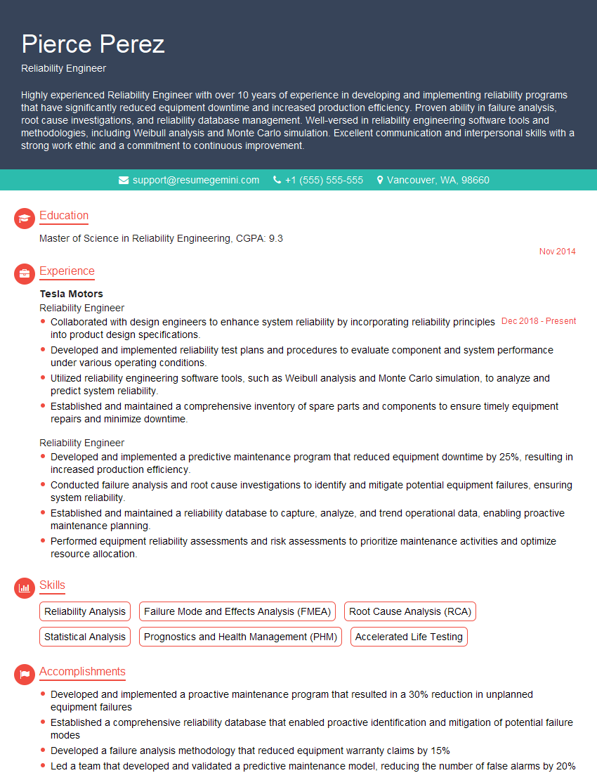
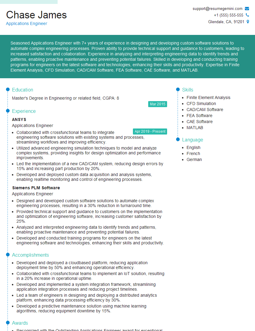
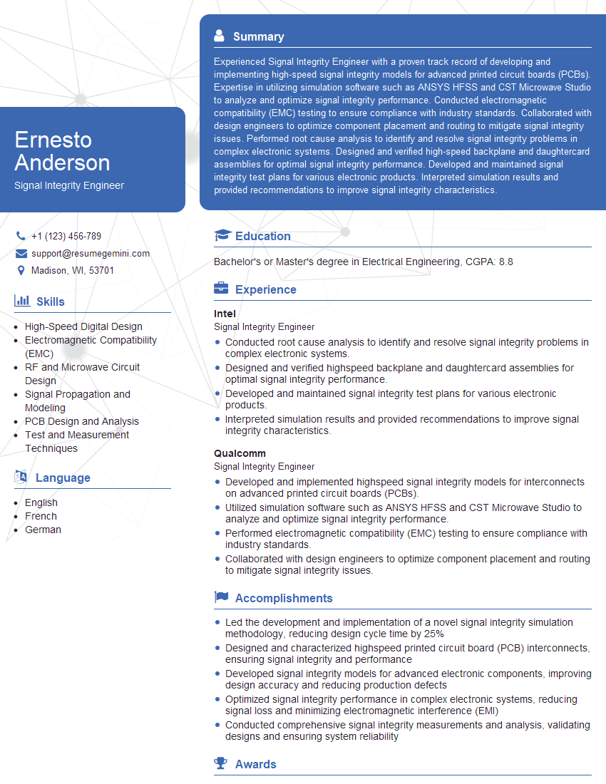
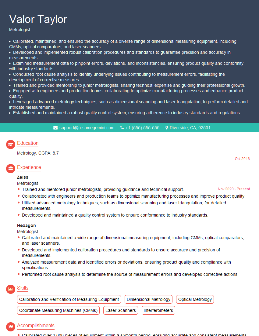
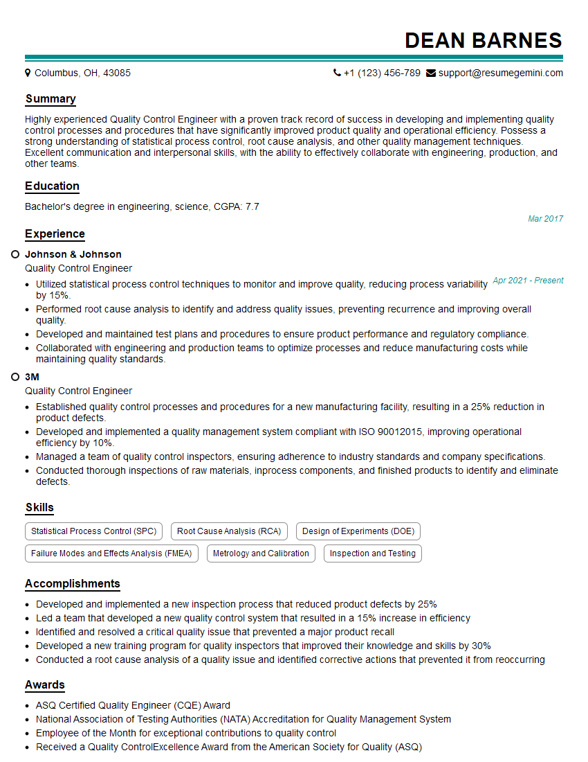
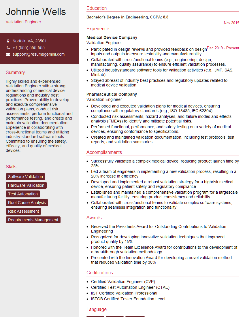
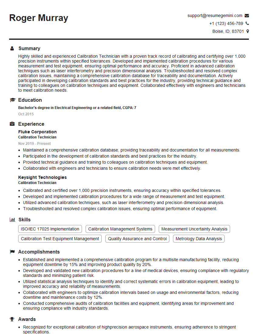
Mastering Test and Measurement Equipment Operation is crucial for a successful and rewarding career in engineering and related fields. It opens doors to diverse opportunities and allows you to contribute significantly to product development, quality control, and research. To maximize your job prospects, it’s essential to create a compelling and ATS-friendly resume that highlights your skills and experience. ResumeGemini is a trusted resource that can help you build a professional resume tailored to the specific requirements of Test and Measurement Equipment Operation roles. Examples of resumes tailored to this field are available to help guide you.
Explore more articles
Users Rating of Our Blogs
Share Your Experience
We value your feedback! Please rate our content and share your thoughts (optional).
What Readers Say About Our Blog
Hello,
We found issues with your domain’s email setup that may be sending your messages to spam or blocking them completely. InboxShield Mini shows you how to fix it in minutes — no tech skills required.
Scan your domain now for details: https://inboxshield-mini.com/
— Adam @ InboxShield Mini
Reply STOP to unsubscribe
Hi, are you owner of interviewgemini.com? What if I told you I could help you find extra time in your schedule, reconnect with leads you didn’t even realize you missed, and bring in more “I want to work with you” conversations, without increasing your ad spend or hiring a full-time employee?
All with a flexible, budget-friendly service that could easily pay for itself. Sounds good?
Would it be nice to jump on a quick 10-minute call so I can show you exactly how we make this work?
Best,
Hapei
Marketing Director
Hey, I know you’re the owner of interviewgemini.com. I’ll be quick.
Fundraising for your business is tough and time-consuming. We make it easier by guaranteeing two private investor meetings each month, for six months. No demos, no pitch events – just direct introductions to active investors matched to your startup.
If youR17;re raising, this could help you build real momentum. Want me to send more info?
Hi, I represent an SEO company that specialises in getting you AI citations and higher rankings on Google. I’d like to offer you a 100% free SEO audit for your website. Would you be interested?
Hi, I represent an SEO company that specialises in getting you AI citations and higher rankings on Google. I’d like to offer you a 100% free SEO audit for your website. Would you be interested?
good
