Unlock your full potential by mastering the most common 2D and 3D Computer-Aided Design (CAD) Software interview questions. This blog offers a deep dive into the critical topics, ensuring you’re not only prepared to answer but to excel. With these insights, you’ll approach your interview with clarity and confidence.
Questions Asked in 2D and 3D Computer-Aided Design (CAD) Software Interview
Q 1. What are the key differences between 2D and 3D CAD software?
The core difference between 2D and 3D CAD lies in their representation of objects. 2D CAD software, like AutoCAD LT, creates drawings on a flat plane, using lines, arcs, and text to represent objects as seen from a single viewpoint. Think of it like a blueprint: you see only the outlines and dimensions. 3D CAD software, like SolidWorks or Autodesk Inventor, creates three-dimensional models, representing length, width, and height. This allows for a complete virtual representation of the object, allowing you to view it from any angle and even simulate its behavior under different conditions.
- 2D CAD: Primarily used for drafting, creating detailed drawings from existing designs, and documenting dimensions. Good for simple geometries and plans.
- 3D CAD: Used for designing complex shapes, performing simulations, creating photorealistic renderings, and generating manufacturing documentation (e.g., CNC machining instructions). Essential for product design and engineering.
Imagine designing a house: 2D CAD would give you floor plans, elevations, and sections. 3D CAD would allow you to virtually walk through the house, analyze lighting and shadows, and ensure all components fit together before construction.
Q 2. Explain your experience with [Specific CAD software, e.g., AutoCAD, SolidWorks].
I have extensive experience with SolidWorks, accumulating over seven years of hands-on usage in various engineering projects. My proficiency spans the entire design lifecycle, from initial concept sketches to detailed manufacturing drawings. I’m comfortable using a wide array of SolidWorks tools, including part modeling, assembly design, drawing creation, simulation analysis (FEA), and rendering.
For instance, in a recent project involving the design of a complex robotic arm, I utilized SolidWorks’ advanced features for kinematic simulation to ensure smooth and efficient joint movements. I also employed FEA analysis to assess stress and strain on critical components under various load conditions. The SolidWorks environment allowed for collaborative design review, enabling efficient feedback and design iteration within our team.
Beyond specific features, I’m adept at leveraging SolidWorks’ parametric modeling capabilities, enabling efficient design changes and ensuring design consistency across multiple iterations. This is critical for managing design complexity and maintaining data integrity.
Q 3. Describe your process for creating detailed technical drawings.
Creating detailed technical drawings involves a systematic approach. It begins with a well-defined 3D model that accurately represents the design. I typically follow these steps:
- Model Review: Thorough inspection of the 3D model to ensure geometric accuracy and completeness. This includes verifying dimensions, tolerances, and surface finish requirements.
- View Creation: Selecting appropriate views (e.g., front, top, side, isometric) needed to clearly communicate the design intent.
- Dimensioning and Tolerancing: Precisely adding dimensions and GD&T (Geometric Dimensioning and Tolerancing) symbols to ensure manufacturing accuracy.
- Annotation: Including necessary notes, material specifications, and part numbers for clarity.
- Sheet Layout: Arranging views and annotations on the drawing sheet in a clear and organized manner according to drafting standards (e.g., ASME Y14.5).
- Review and Quality Check: Careful review of the drawing to identify and correct any errors before finalization.
For example, when creating drawings for a complex mechanical assembly, I ensure that all parts are properly dimensioned and that mating surfaces are clearly indicated. I also utilize drawing templates to ensure consistency and compliance with company standards.
Q 4. How do you handle revisions and updates to CAD models?
Handling revisions and updates to CAD models requires a structured approach to maintain data integrity and prevent errors. My approach includes:
- Version Control: Utilizing the built-in version control features of the CAD software (e.g., SolidWorks’ Revision Management) or external version control systems (e.g., Git) to track changes and revert to previous versions if needed.
- Change Management System: Implementing a formal change management process involving clear documentation of all changes, approval workflows, and notification to relevant stakeholders.
- Data Backup: Regular backups of CAD models and drawings to prevent data loss due to software crashes or hardware failures.
- Naming Conventions: Implementing a consistent naming convention for files to easily identify revisions and versions.
For instance, if a design flaw is discovered after a model is finalized, I create a new revision, documenting the changes made, and update the drawing accordingly. The previous version is retained for historical reference.
Q 5. What are some common file formats used in CAD and their applications?
Several common file formats are used in CAD, each with its own application:
- .STEP (.stp, .step): A neutral format for exchanging 3D CAD data between different software packages. It’s widely used for collaboration and data transfer between different engineering teams.
- .IGES (.igs, .iges): Similar to STEP, another neutral format for exchanging 3D CAD data but often less preferred due to potential data loss.
- .DXF (.dxf): A widely used format for exchanging 2D CAD data between different software packages, often used for importing/exporting drawings to and from AutoCAD.
- .DWG (.dwg): Autodesk’s native format for AutoCAD, offering maximum compatibility within the AutoCAD ecosystem.
- .STL (.stl): A widely used format for 3D printing and rapid prototyping. It represents the surface of the object as a mesh of triangles.
Choosing the right format is critical for ensuring data compatibility and efficient collaboration. For example, using STEP ensures that models can be easily shared between teams using different CAD software without data loss.
Q 6. Explain your experience with CAD modeling techniques (e.g., solid modeling, surface modeling).
I have extensive experience with various CAD modeling techniques, primarily solid modeling and surface modeling. The choice of technique depends largely on the design requirements and the desired outcome.
- Solid Modeling: This creates a fully defined 3D model with volume, mass, and material properties. It’s ideal for engineering applications requiring accurate representation of the physical object, such as stress analysis or manufacturing process simulations. Examples include using features like extrude, revolve, and sweep in SolidWorks to create complex parts from simpler geometry.
- Surface Modeling: This creates a 3D model based on surfaces rather than solids. It is particularly suitable for designing organic shapes or free-form surfaces, often used in automotive, aerospace, and industrial design for creating aesthetically pleasing products. This technique focuses on visually appealing surfaces, rather than the object’s internal structure.
For example, designing a mechanical part would necessitate solid modeling to ensure accurate tolerances and structural integrity. In contrast, designing a car body would likely involve surface modeling to shape the outer shell and then build a solid model based on the surfaces created.
Q 7. How do you ensure dimensional accuracy in your CAD models?
Dimensional accuracy in CAD models is paramount for successful manufacturing and product functionality. I ensure accuracy through these methods:
- Precise Input: Entering dimensions and constraints carefully using the appropriate units. Double-checking all numerical inputs for accuracy.
- Geometric Constraints: Using geometric constraints to define relationships between different features of the model, ensuring dimensional consistency even after design modifications.
- Parametric Modeling: Leveraging parametric modeling techniques, where dimensions are linked to parameters. This allows for efficient modification of the model by changing parameter values and automatically updating the model geometry.
- Design Reviews: Conducting thorough design reviews with colleagues to identify and correct any dimensional errors early in the design process.
- Tolerance Analysis: Performing tolerance analysis to assess the impact of manufacturing tolerances on the final product’s dimensions and functionality. This involves defining tolerances for each dimension and evaluating their cumulative effect.
Regularly checking dimensions and utilizing the model’s measurement tools help prevent inaccuracies and ensure a high degree of dimensional accuracy.
Q 8. Describe your experience with CAD data management and version control.
Effective CAD data management is crucial for any project’s success. It ensures data integrity, prevents conflicts, and allows for efficient collaboration. My experience encompasses using various version control systems, primarily PDM (Product Data Management) systems integrated with CAD software like Autodesk Vault or SolidWorks PDM. These systems allow for centralized storage of CAD files, revision tracking, and workflow management. Think of it like a sophisticated library for your CAD models, where every version is meticulously tracked and accessible.
For example, imagine working on a complex engine design with multiple engineers. Without a PDM system, managing different versions of parts and assemblies could become chaotic. A PDM system prevents conflicts, allows us to easily revert to previous versions if needed, and provides a clear audit trail of all changes. I’ve personally utilized check-in/check-out procedures, version numbering schemes, and metadata tagging to maintain consistent and organized data. This ensures traceability and prevents accidental overwrites, saving time and preventing costly errors.
Q 9. How do you manage large and complex CAD assemblies?
Managing large and complex CAD assemblies requires a strategic approach. It’s not just about having powerful hardware; it’s about employing smart techniques. My strategy involves leveraging the capabilities of the CAD software to its fullest extent. This includes using techniques like component suppression, lightweight components, and design simplification where possible.
For instance, if I’m working on a car model, I might create simplified representations of components like the engine or interior for initial assembly checks, only detailing these sub-assemblies when necessary. I also frequently utilize top-down design, breaking down the main assembly into smaller, manageable sub-assemblies. This allows for parallel work by team members and makes the assembly less computationally intensive. Further, efficient component organization and naming conventions, using structured folders and consistent naming standards is key. This is essential for easily finding parts within massive assemblies. Finally, regular performance checks and optimization of the assembly are crucial to prevent performance bottlenecks during rendering or simulation.
Q 10. Explain your understanding of CAD standards and best practices.
Adherence to CAD standards and best practices is paramount for ensuring consistency, collaboration, and data exchange. These standards cover aspects like file naming conventions, layer management, geometric tolerancing, and data exchange formats.
- File Naming: I consistently use a structured naming system reflecting project, part number, revision, and date (e.g., Project_ABC_Part123_RevA_20240308.sldprt).
- Layer Management: Organizing layers logically helps to streamline the design process and simplifies future modifications.
- Geometric Dimensioning and Tolerancing (GD&T): I use GD&T to clearly define manufacturing tolerances, ensuring parts fit together as intended.
- Data Exchange: Familiarity with various CAD formats (STEP, IGES, DXF) is essential for seamless collaboration with external partners and clients.
These practices guarantee that designs are easily understandable, manageable, and suitable for manufacturing. Ignoring standards can lead to confusion, errors, and ultimately, project delays and cost overruns. I regularly refer to industry-specific standards and company-specific guidelines to ensure my work meets the highest quality standards.
Q 11. How do you troubleshoot errors and issues in your CAD models?
Troubleshooting errors in CAD models requires a systematic approach. I usually start by identifying the symptoms: Is it a rendering issue, a geometric error, or a data corruption problem?
My troubleshooting process often involves:
- Visual Inspection: A careful visual examination of the model can often pinpoint obvious errors like intersecting surfaces or missing geometry.
- Checking History: Reviewing the design history can often pinpoint the source of the error. Parametric models allow me to trace back to the origin of the problem.
- Using Diagnostic Tools: Most CAD software provides diagnostic tools to help identify and resolve issues. For example, SolidWorks offers tools to check for geometry problems, while Autodesk Inventor has tools to analyze model performance.
- Simplify the Model: Temporarily removing or simplifying parts of the model can help to isolate the source of the problem.
- Rebuilding or Repairing: In extreme cases, rebuilding or repairing parts of the model may be necessary.
For example, a sudden crash could be due to a memory leak or corrupted file. Regularly saving the work and cleaning up unnecessary data help prevent this. A systematic approach and understanding of CAD software’s capabilities are vital to effectively troubleshoot issues.
Q 12. Describe your experience with rendering and visualization in CAD.
Rendering and visualization are key to effectively communicating design intent. My experience extends to using various rendering techniques and software, from basic CAD software renderers to dedicated rendering packages like Keyshot or V-Ray.
I understand the importance of selecting appropriate rendering techniques depending on the project requirements. For example, a quick, low-quality render might suffice for early design reviews, while photorealistic renders are critical for client presentations and marketing materials. I’m proficient in setting up lighting, materials, and cameras to create impactful visuals. I’ve also worked with animation to showcase moving parts or assembly processes, enhancing the understanding of the design.
Imagine presenting a new product design to a client. A high-quality render can significantly improve the impact of the presentation, conveying the product’s aesthetics and functionality more effectively than simple wireframe models.
Q 13. How do you collaborate with other team members using CAD software?
Collaboration is crucial in CAD design. I have extensive experience collaborating using various methods, including:
- PDM Systems: As mentioned earlier, PDM systems enable multiple users to access and modify CAD models while managing versions effectively.
- Cloud-based Collaboration Platforms: Platforms like Autodesk Fusion Team or similar tools provide real-time collaboration capabilities allowing simultaneous editing and commenting on designs.
- Data Exchange Formats: Using neutral file formats (STEP, IGES) allows seamless data exchange between different CAD platforms and software versions.
- Regular Meetings and Reviews: Regular design reviews and meetings ensure everyone is on the same page and potential conflicts are addressed early.
For instance, in a team project, we often use cloud-based platforms to simultaneously work on different aspects of the same design, with comment sections to track changes and facilitate quick communication. Clear communication and a well-defined workflow are key to successful team collaboration.
Q 14. How familiar are you with parametric modeling?
Parametric modeling is the foundation of my CAD design approach. It allows me to create models based on parameters and relationships rather than just fixed geometry. This is like building with Lego bricks – instead of gluing them together, you connect them using standardized connections, allowing for easy modification.
The advantages are immense: Changes to a single parameter automatically update the entire model, ensuring consistency and reducing errors. For example, if I’m designing a gear, I can define parameters like the number of teeth, module, and pressure angle. Changing any of these parameters automatically updates the entire gear geometry, saving significant time and effort. Parametric modeling is not just efficient; it fosters design exploration, allowing quick iterations and design optimizations. I routinely use parametric modeling to explore different design options and analyze their impact on the overall product.
Q 15. Explain your experience with creating detailed manufacturing drawings.
Creating detailed manufacturing drawings is a crucial aspect of my CAD workflow. It involves more than just pretty pictures; it’s about providing precise, unambiguous instructions for manufacturing. My experience includes generating 2D drawings with dimensions, tolerances, material specifications, surface finishes, and assembly instructions, all adhering to industry standards like ASME Y14.5.
For instance, in a recent project designing a complex robotic arm, I created detailed drawings of each component – from the individual links and joints to the motor housings and wiring conduits. These drawings included orthographic views (front, top, side), sectional views to show internal features, and detailed annotations specifying dimensions, tolerances (e.g., ±0.05mm), and surface finish requirements (e.g., Ra 0.8µm). I also created assembly drawings showing how the components fit together, along with a bill of materials (BOM) listing every part needed.
I’m proficient in generating various drawing views, including isometric and exploded views to clarify assembly procedures. I’m also familiar with creating detailed GD&T (Geometric Dimensioning and Tolerancing) annotations to ensure the manufactured parts meet the required precision. All drawings are meticulously checked for accuracy and completeness before release to manufacturing.
Career Expert Tips:
- Ace those interviews! Prepare effectively by reviewing the Top 50 Most Common Interview Questions on ResumeGemini.
- Navigate your job search with confidence! Explore a wide range of Career Tips on ResumeGemini. Learn about common challenges and recommendations to overcome them.
- Craft the perfect resume! Master the Art of Resume Writing with ResumeGemini’s guide. Showcase your unique qualifications and achievements effectively.
- Don’t miss out on holiday savings! Build your dream resume with ResumeGemini’s ATS optimized templates.
Q 16. How do you use CAD software for design analysis and simulation?
CAD software isn’t just for visualization; it’s a powerful tool for design analysis and simulation. I leverage its capabilities to predict how a design will perform under various conditions before it’s even built. This minimizes costly redesigns and ensures the final product meets the required specifications.
For example, I use Finite Element Analysis (FEA) capabilities within my CAD software to simulate stress and strain on components under load. This allows me to identify potential weak points in a design and optimize the geometry to enhance its strength and durability. I’ve used FEA to analyze everything from the structural integrity of a bridge to the stress distribution in a complex injection-molded part.
Furthermore, I utilize computational fluid dynamics (CFD) simulations to analyze airflow and fluid flow characteristics within designs. This is particularly useful in designing systems involving air conditioning, ventilation, or fluid transport, where I can optimize the design to enhance efficiency and minimize turbulence. Visualizing these simulations helps in identifying areas for improvement and refining the design iteratively.
Q 17. Describe your experience with CAD-CAM integration.
CAD-CAM integration is crucial for efficient manufacturing. It’s the seamless flow of data from the design stage (CAD) to the manufacturing stage (CAM). I have extensive experience in this area, utilizing CAM software to generate toolpaths for CNC machining, 3D printing, and other manufacturing processes directly from my CAD models.
In one project involving the creation of a custom aluminum chassis, I used a CAD model to define the exact geometry. This model was then directly imported into CAM software, where I programmed toolpaths for a CNC milling machine. The CAM software accounted for factors like tool size, cutting speeds, and feed rates, automatically generating efficient machining strategies to minimize production time and material waste. This direct integration significantly reduced errors and sped up the manufacturing process, ensuring a smooth transition from design to production.
I’m proficient in using various CAM features like toolpath optimization, collision avoidance, and simulation to validate the manufacturing process before commencing actual machining. This proactive approach to CAM integration helps to avoid potential manufacturing issues and ensures high-quality output.
Q 18. How do you ensure the accuracy of your CAD models against design specifications?
Ensuring the accuracy of CAD models against design specifications is paramount. My approach involves a multi-step process that combines meticulous modeling techniques and rigorous verification methods.
First, I start with precise input data, ensuring all dimensions, tolerances, and material properties are accurately defined based on the design specifications. I then rigorously verify the model using built-in CAD tools for geometric dimensioning and tolerancing (GD&T) checks. This ensures that the model meets all the specified geometric constraints and tolerances.
Furthermore, I regularly perform design reviews and utilize model checking tools to identify any potential errors or inconsistencies in the model. These tools can automatically detect gaps, overlaps, or other geometric anomalies. I also use section analysis and measurements to verify that the model aligns precisely with the design specifications, paying close attention to critical dimensions and tolerances. For complex assemblies, I conduct interference checks to ensure parts fit together without clashes.
Q 19. What are some limitations of CAD software, and how do you address them?
While CAD software is powerful, it does have limitations. One common issue is file size, especially with complex assemblies. Large file sizes can lead to slow performance and difficulty in data management. I address this by using techniques like component referencing and simplifying geometry where possible, while retaining the required detail.
Another limitation is the software’s inability to perfectly capture the nuances of real-world manufacturing processes. For instance, the software may not accurately predict the effects of material deformation during machining or the impact of manufacturing tolerances on the final assembly. To mitigate this, I incorporate design for manufacturability (DFM) principles throughout the design process and collaborate closely with manufacturing engineers to address potential challenges early on.
Finally, limitations in software features may occasionally restrict the design space. In such situations, I consider alternative modeling techniques or explore using add-ons or plugins to expand the software’s capabilities. When necessary, I’m also comfortable leveraging multiple software packages to overcome specific limitations, combining their strengths for a comprehensive design workflow.
Q 20. Explain your proficiency in various CAD tools and commands.
My proficiency spans various CAD tools and commands across multiple platforms, including SolidWorks, AutoCAD, and Autodesk Inventor. I’m comfortable with 2D and 3D modeling techniques, including parametric modeling, surface modeling, and solid modeling. My expertise encompasses a wide range of commands and functionalities within these software packages.
For example, in SolidWorks, I’m proficient in using features like extrude, revolve, sweep, and loft to create complex geometries. I’m adept at creating and managing assemblies, utilizing constraints and mates to accurately define relationships between parts. In AutoCAD, I’m highly skilled in 2D drafting, generating detailed drawings with precise dimensions and annotations. My experience with Autodesk Inventor includes creating and manipulating parametric 3D models, performing simulations and generating detailed manufacturing drawings. I’m also familiar with scripting and macros to automate repetitive tasks, increasing efficiency and accuracy.
Beyond specific commands, I understand the underlying principles of CAD modeling, allowing me to effectively adapt to new software and utilize its capabilities to achieve design goals efficiently.
Q 21. How do you stay updated on the latest developments in CAD software and technologies?
Staying current with the rapid advancements in CAD software and technologies is critical. I employ several strategies to ensure I remain at the forefront of this field.
I actively participate in online courses and workshops offered by software vendors and industry organizations. This provides hands-on training and exposure to the latest features and techniques. I also regularly attend industry conferences and webinars to learn about emerging trends and best practices from leading experts. Following industry blogs, journals, and online forums allows me to stay informed about new developments and discuss challenges with other professionals.
Furthermore, I dedicate time to self-learning through online tutorials, documentation, and experimentation with new software features and techniques. This hands-on approach ensures I can effectively apply new technologies to real-world projects. Continuous learning and adaptation are essential to maintaining a high level of proficiency in this ever-evolving field.
Q 22. Describe your experience with creating and using CAD libraries and templates.
Creating and utilizing CAD libraries and templates is crucial for efficiency and consistency in design. Think of them as pre-built components and standardized structures that significantly speed up the design process. I have extensive experience building and managing these libraries, both in 2D (e.g., AutoCAD) and 3D (e.g., SolidWorks, Inventor) environments.
- Library Creation: I’ve developed libraries containing frequently used parts like standard fasteners (bolts, nuts, screws), connectors, and commonly shaped components. This involves meticulous parameterization to ensure reusability and easy modification. For example, a bolt library might include parameters for diameter, length, and thread type, allowing for quick selection and customization.
- Template Development: I’ve created templates for various design tasks, such as sheet metal parts, assembly drawings, and 3D models with pre-defined views and annotations. These templates enforce company standards and ensure consistency across projects. A good example would be a template for a circuit board housing, pre-populated with mounting holes and standardized dimensions.
- Library Management: Maintaining and updating libraries and templates is an ongoing process. This includes regular checks for outdated parts, version control, and proper documentation to ensure that everyone on the team knows where to find and how to use them effectively. This often involves implementing a version control system.
By leveraging these resources, I can dramatically reduce design time, minimize errors, and ensure design consistency across projects.
Q 23. How do you handle conflicts between design requirements and manufacturing constraints?
Balancing design requirements with manufacturing constraints is a critical aspect of successful product development. It’s like navigating a tightrope – you need the vision of the designer and the pragmatism of the manufacturer. I approach this through iterative design and close collaboration.
- Early Collaboration: I actively involve manufacturing engineers early in the design process. This ensures that design choices consider manufacturing capabilities (e.g., material availability, machining limitations, assembly methods).
- Design for Manufacturing (DFM): I incorporate DFM principles throughout the design process. This includes simplifying geometries, selecting manufacturable materials, and considering assembly ease. For instance, opting for a simpler part geometry might be preferable to a more complex one, even if it compromises slight aesthetic preferences, when considering cost and production.
- Tolerance Analysis: I perform tolerance analysis using GD&T (discussed in the next question) to assess the impact of dimensional variations on part functionality and assembly. This allows for early identification and resolution of potential issues.
- Compromise and Iteration: Sometimes compromises are necessary. I work collaboratively with stakeholders to identify the best balance between functionality, aesthetics, and manufacturability. This often involves iterative design cycles, where design adjustments are made based on feedback from manufacturing and testing.
A successful outcome involves a product that meets design goals without exceeding manufacturing limitations, ultimately leading to a cost-effective and reliable final product.
Q 24. Explain your understanding of geometric dimensioning and tolerancing (GD&T).
Geometric Dimensioning and Tolerancing (GD&T) is a standardized system for specifying the size, form, orientation, location, and runout of features on a part. It’s the language of precision engineering, ensuring parts fit together correctly and function as intended. Understanding GD&T is fundamental for communicating design intent clearly to manufacturers.
My understanding of GD&T encompasses:
- Basic Symbols: I am proficient in using and interpreting symbols for various geometric characteristics, such as flatness, straightness, circularity, cylindricity, parallelism, perpendicularity, angularity, position, and runout.
- Datum References: I understand the importance of establishing datums (reference points or surfaces) for accurate dimensioning and tolerance specification. This ensures consistency in part measurement and assembly.
- Tolerance Zones: I can define tolerance zones for features and understand how these zones affect part interchangeability and functionality.
- Feature Control Frames: I am experienced in creating and interpreting feature control frames, which provide precise instructions on allowable deviations from nominal dimensions.
Applying GD&T prevents costly mistakes during manufacturing by precisely defining acceptable variations. For example, specifying the positional tolerance of a mounting hole ensures it aligns correctly with its mating part, preventing assembly issues.
Q 25. How do you optimize CAD models for efficient rendering and animation?
Optimizing CAD models for rendering and animation involves techniques that reduce polygon count and simplify geometry without significantly impacting visual quality. It’s about striking a balance between visual fidelity and rendering performance.
- Polygon Reduction: I use various techniques to reduce the number of polygons in a model. This might involve decimation (reducing polygon density), mesh simplification algorithms, or using lower-resolution models for less important areas.
- Level of Detail (LOD): I implement LODs, which utilize multiple versions of a model with varying levels of detail. A high-detail model is used for close-up views, while a lower-detail model is used for distant views, improving performance without sacrificing visual quality.
- Texture Optimization: Using optimized textures (smaller file size, appropriate resolution) significantly improves rendering speeds. Techniques include compression, mipmapping, and atlasing.
- Model Simplification: I simplify model geometry wherever possible without compromising visual fidelity. This might involve removing unnecessary details or combining simpler shapes.
- Software-Specific Optimizations: I leverage the optimization tools available in specific rendering and animation software (e.g., Maya, 3ds Max, Blender) to streamline the process and improve rendering times.
These optimization techniques are crucial for creating smooth animations and high-quality renderings, particularly for large or complex models, ensuring efficient project workflows and avoiding long rendering times.
Q 26. Describe your experience with different types of CAD projections (e.g., isometric, orthographic).
Different CAD projections serve distinct purposes in visualizing 3D models. Understanding and using them effectively is vital for clear communication and accurate representation.
- Orthographic Projections: These are 2D views of a 3D object, representing the object from different orthogonal viewpoints (top, front, side). They provide precise dimensions and are essential for manufacturing drawings. I frequently use orthographic projections in creating detailed technical drawings for manufacturing and assembly.
- Isometric Projections: These are 3D projections where three axes are equally foreshortened. They offer a quick visual representation of the object’s overall shape and proportions. I often use isometric views to provide a general overview of an assembly or to communicate a design’s three-dimensional shape in a concise manner.
- Axonometric Projections: This is a broader category encompassing isometric, dimetric, and trimetric projections, differing in the angles of projection. My experience encompasses using these various projections to create effective visual representations depending on the specific needs of the design communication.
- Perspective Projections: Although less frequently used in detailed design drawings, perspective projections provide a more realistic representation that reflects how the human eye perceives depth. I utilize them when creating visualizations intended for marketing or presentations.
Choosing the appropriate projection type depends on the intended use – orthographic for precision, isometric for quick visualization, and perspective for realistic representation.
Q 27. How familiar are you with creating and using custom macros or scripts in CAD?
I’m highly proficient in creating and using custom macros and scripts in CAD software. Automation is key to boosting efficiency and consistency in design.
- AutoCAD LISP/AutoLISP: I’ve written LISP routines for automating repetitive tasks, such as generating complex patterns, creating custom annotations, and extracting data from drawings.
- SolidWorks Macros (VBA): In SolidWorks, I utilize VBA (Visual Basic for Applications) to automate model generation, modify existing models, and streamline assembly processes. I’ve created macros to automate tasks like creating families of parts with varying dimensions or automatically generating assembly drawings.
- API Interaction: I understand the principles of CAD software APIs (Application Programming Interfaces) and how to leverage them for more advanced automation tasks. This enables integration with other software and data sources.
- Python Scripting: I also use Python, which offers a powerful and versatile scripting language for a wide range of CAD automation tasks, including model generation, data extraction, and analysis.
For example, I created a macro to automatically generate a family of parts with different lengths, reducing manual entry time substantially. The use of scripting and macros allows for repeatable tasks that improve accuracy and save significant time.
Q 28. What is your preferred workflow for creating a complex CAD model from a sketch or concept?
My workflow for creating complex CAD models from a sketch or concept involves a structured approach that prioritizes clarity, precision, and iterative refinement.
- Concept Refinement: I begin by refining the initial sketch or concept, often using digital sketching tools or 2D CAD to flesh out details and clarify design intent. This clarifies the overall vision and anticipates potential problems.
- Feature-Based Modeling: I strongly favor feature-based modeling techniques (as opposed to purely direct modeling) in 3D CAD. This approach allows for parametric control and easy modification of the model. Adding features like extrudes, revolves, and cuts in a logical order establishes clear relationships and improves design control.
- Constraints and Relations: I utilize constraints and relations extensively to define relationships between parts in an assembly. This enables robust design, ensuring the model remains consistent and manageable as changes are made. This helps prevent geometrical inconsistencies and ensures model integrity.
- Iterative Design and Verification: Throughout the modeling process, I perform regular checks and iterations, utilizing simulation and analysis tools to ensure the design meets requirements. This allows for early detection of potential design flaws.
- Documentation: Finally, I meticulously document the design process, including sketches, CAD models, and any simulation or analysis results. This ensures clear design intent and simplifies collaboration.
This phased approach, focusing on clear communication and iteration, ensures a high-quality and reliable final product.
Key Topics to Learn for 2D and 3D Computer-Aided Design (CAD) Software Interview
- 2D CAD Fundamentals: Understanding drawing tools, geometric constraints, dimensioning techniques, and layer management in software like AutoCAD or DraftSight. Practical application: Creating detailed technical drawings for manufacturing.
- 3D CAD Modeling: Mastering techniques like extrusion, revolution, sweeping, and boolean operations in software such as SolidWorks, Inventor, or Fusion 360. Practical application: Designing complex parts and assemblies for various industries.
- CAD Software Specifics: Become proficient in the specific software requested in the job description. Familiarize yourself with its interface, shortcuts, and unique features.
- Design Principles: Understanding principles of engineering design, including tolerance analysis, material selection, and manufacturability considerations. Practical application: Creating designs that are both functional and cost-effective to produce.
- Data Management: Learn about file formats, version control, and data exchange between different CAD software packages. Practical application: Collaborating effectively on large projects.
- Advanced Techniques (depending on role): Explore topics such as parametric modeling, surface modeling, simulation (FEA, CFD), rendering, and animation, as relevant to the specific job requirements.
- Problem-Solving and Troubleshooting: Be prepared to discuss how you approach and resolve technical challenges encountered during the design process.
Next Steps
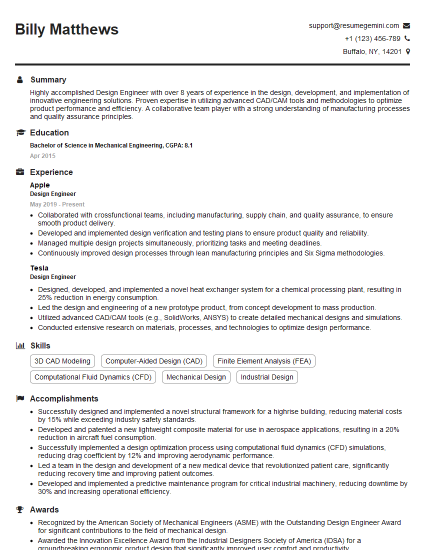
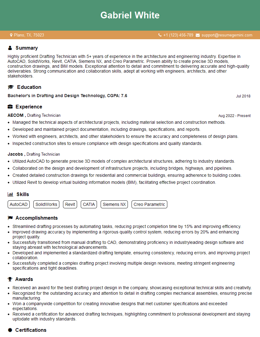
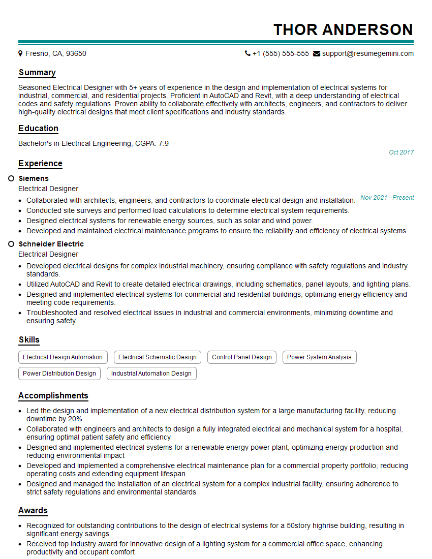
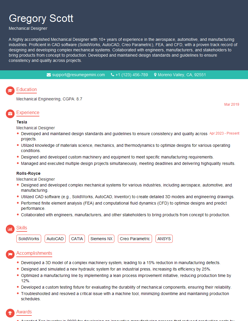
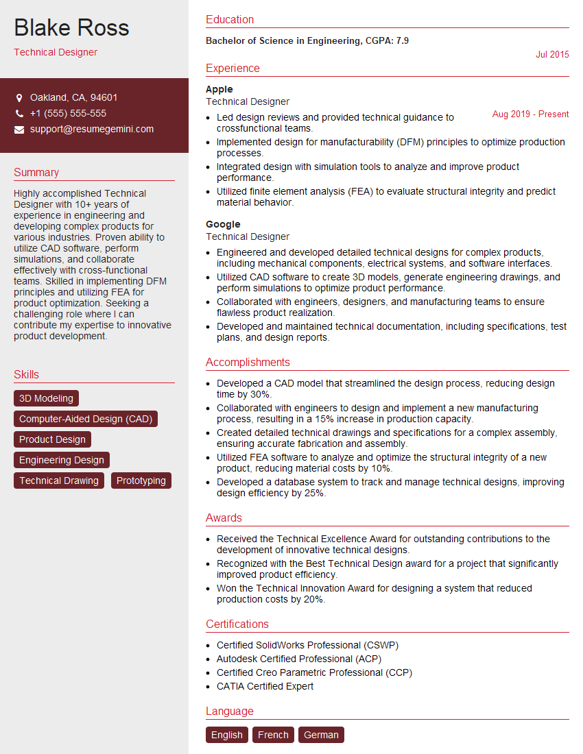
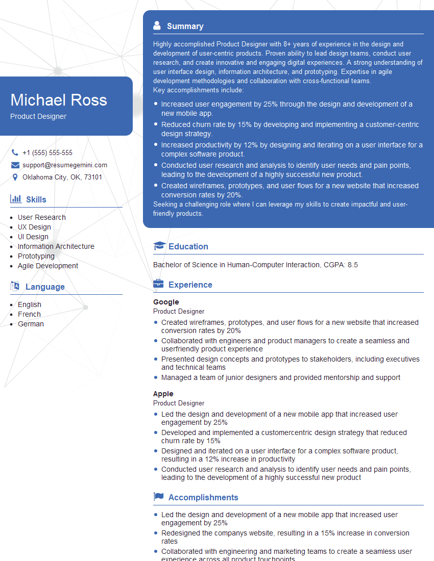
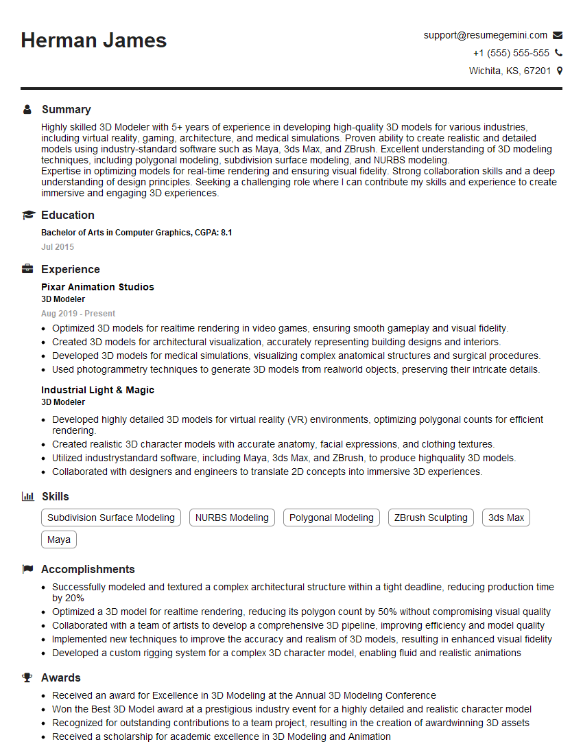
Mastering 2D and 3D CAD software opens doors to exciting and rewarding careers in various fields, from manufacturing and aerospace to architecture and automotive design. To maximize your job prospects, it’s crucial to present your skills effectively. Crafting an ATS-friendly resume is key to getting your application noticed. ResumeGemini is a trusted resource to help you build a professional and impactful resume that highlights your CAD expertise. We provide examples of resumes tailored to 2D and 3D CAD Software roles to guide you through the process. Take the next step towards your dream career – build your best resume today!
Explore more articles
Users Rating of Our Blogs
Share Your Experience
We value your feedback! Please rate our content and share your thoughts (optional).
What Readers Say About Our Blog
Very informative content, great job.
good