Cracking a skill-specific interview, like one for Detailing and Assembly Drawings, requires understanding the nuances of the role. In this blog, we present the questions you’re most likely to encounter, along with insights into how to answer them effectively. Let’s ensure you’re ready to make a strong impression.
Questions Asked in Detailing and Assembly Drawings Interview
Q 1. Explain the difference between a detail drawing and an assembly drawing.
The core difference between detail and assembly drawings lies in their scope and purpose. A detail drawing focuses on a single component or part, providing all the necessary information for its manufacture. Think of it as a recipe for a single ingredient. It shows dimensions, tolerances, materials, and manufacturing processes for that specific part in meticulous detail. An assembly drawing, on the other hand, shows how multiple parts fit together to form a complete assembly or sub-assembly. It’s like the recipe for the whole dish, showing how the individual ingredients (parts) are combined. It illustrates the spatial relationships between components, often including exploded views to clarify assembly sequences. In essence, detail drawings are the building blocks, while assembly drawings are the blueprints of the final product.
Example: A detail drawing might show the precise dimensions and tolerances of a single bolt, including its head shape, thread pitch, and material. An assembly drawing for a bicycle would show how the frame, wheels, handlebars, and other components are interconnected.
Q 2. What are the common standards and conventions used in creating detail and assembly drawings?
Standardization is crucial for clear communication in engineering. Common standards and conventions include:
- Drawing scales: Using consistent scales (e.g., 1:1, 1:2, 1:10) ensures accurate representation.
- Line types: Different line types (solid, dashed, dotted) represent different features (visible lines, hidden lines, centerlines).
- Dimensioning and tolerancing: Following standards like ASME Y14.5 (US) or ISO (International) ensures consistent interpretation of dimensions and allowable variations.
- Sheet sizes: Adhering to standard sheet sizes (e.g., A0, A1, A2) simplifies organization and storage.
- Title blocks: Title blocks provide essential information such as drawing number, title, revision date, and designer’s name.
- Bill of Materials (BOM): Assembly drawings usually include a BOM that lists all the components required for the assembly, their quantities, and part numbers.
These conventions ensure clarity and reduce the risk of misinterpretation, leading to efficient manufacturing and assembly processes.
Q 3. Describe your experience with different CAD software packages (e.g., AutoCAD, SolidWorks, Revit).
Throughout my career, I’ve extensively utilized several CAD packages. My experience includes:
- AutoCAD: Proficient in 2D drafting, creating detail and assembly drawings, and generating documentation. I’ve used AutoCAD for various projects, from architectural drawings to mechanical components, leveraging its powerful command line and extensive libraries of tools. I am comfortable with customizing settings and using LISP routines for automation.
- SolidWorks: SolidWorks is my primary 3D modeling software. I am highly proficient in creating 3D models, generating detailed and assembly drawings directly from the model, and performing simulations. This seamless transition from 3D to 2D is incredibly efficient and minimizes errors.
- Revit: While primarily focused on architectural and structural design, I have experience using Revit for creating building information models (BIM) and extracting 2D drawings from them. This experience is valuable in understanding the broader context of drawings within larger projects.
My ability to adapt between these programs provides flexibility and allows me to leverage the strengths of each software depending on the specific project requirements.
Q 4. How do you ensure accuracy and precision in your drawings?
Accuracy and precision are paramount. My approach involves several key steps:
- Precise Measurements: Starting with accurate measurements from physical models or 3D scans is critical. This forms the foundation for accurate drawings.
- Verification and Validation: Regularly reviewing the drawings to check for dimensional consistency, geometrical accuracy, and adherence to standards is essential. I use various tools, like geometric dimensioning and tolerancing (GD&T) checks within CAD software, to ensure compliance.
- Peer Reviews: Seeking feedback from colleagues provides another layer of quality control. Fresh eyes often spot errors that might have been missed.
- Dimensional Analysis: For complex assemblies, performing dimensional analysis helps to prevent interference and ensure proper fit between parts.
This multi-layered approach ensures a high level of accuracy and minimizes the risk of costly errors during manufacturing.
Q 5. Explain the importance of dimensioning and tolerancing in detail drawings.
Dimensioning and tolerancing are crucial for manufacturing. Dimensions specify the ideal size of a feature, while tolerances define the acceptable range of variation from that ideal. Without accurate dimensioning and tolerancing, manufacturers won’t know what size to make parts, leading to parts that don’t fit together properly, function poorly, or simply fail.
Example: A dimension might specify a shaft diameter as 25mm, with a tolerance of ±0.1mm. This means the acceptable range is between 24.9mm and 25.1mm. The use of GD&T symbols further refines tolerance specifications, clarifying form, orientation, and location tolerances.
Proper dimensioning and tolerancing ensures that manufactured parts meet the design requirements and are interchangeable. It also avoids over-specifying tolerances, which can increase manufacturing costs without adding any real benefit.
Q 6. How do you handle revisions and updates to existing drawings?
Revision control is a cornerstone of effective engineering. My process typically involves:
- Revision Numbering System: Using a clear revision numbering system (e.g., A, B, C, or a numerical system) to track changes ensures that everyone is working from the latest version.
- Revision History: Maintaining a detailed revision history documenting all changes, the reason for the change, and the date of the change is crucial.
- Version Control Software: Utilizing software like Autodesk Vault or similar version control systems helps manage revisions and prevents accidental overwriting of files.
- Notification: Notifying all relevant stakeholders about revisions and providing them with access to the updated drawings is essential.
Proper revision control is vital for maintaining consistent documentation and ensuring everyone is working with the most up-to-date information, preventing costly mistakes.
Q 7. Describe your process for creating a detailed drawing from a 3D model.
Creating a detailed drawing from a 3D model is a highly efficient process. My typical workflow is:
- Model Review: First, I thoroughly review the 3D model to ensure it’s complete and accurate, checking for any inconsistencies or missing features.
- View Selection: I then select the appropriate views (front, top, side, sections, etc.) needed to adequately communicate the design details.
- Dimensioning and Tolerancing: Next, I add dimensions and tolerances using the CAD software’s tools. I pay close attention to clarity and ensure all critical dimensions are included.
- Annotation: I then add annotations, including material specifications, surface finishes, and any other relevant information required for manufacturing.
- BOM Generation: If it’s a part within an assembly, I generate the Bill of Materials (BOM) and include it with the drawing.
- Review and Verification: Finally, I carefully review the generated detailed drawing to ensure its accuracy and completeness before releasing it.
This process leverages the advantages of 3D modeling, significantly reducing the time and effort needed for creating accurate and comprehensive detail drawings. It also minimizes the potential for errors, as the drawing is directly derived from the model.
Q 8. How familiar are you with Geometric Dimensioning and Tolerancing (GD&T)?
Geometric Dimensioning and Tolerancing (GD&T) is a symbolic language used on engineering drawings to precisely define the size, shape, orientation, location, and runout of features. It’s crucial for ensuring parts fit together correctly and function as intended. My familiarity extends to a deep understanding of all its fundamental symbols, including position, parallelism, perpendicularity, flatness, circularity, and cylindricity. I’m proficient in interpreting GD&T callouts on drawings and applying them during the design and manufacturing processes. For example, I’ve successfully utilized GD&T to specify the precise location of mounting holes on a complex chassis, preventing assembly issues and guaranteeing proper functionality.
I understand the difference between unilateral, bilateral, and limit tolerances and can apply this knowledge to create more robust and manufacturable designs. I’m also familiar with the ASME Y14.5 standard, which defines the rules and guidelines for GD&T. This ensures consistent interpretation and avoids potential ambiguity across different teams and manufacturers.
Q 9. How do you manage large and complex assembly drawings?
Managing large and complex assembly drawings requires a structured approach. I typically begin by breaking down the assembly into smaller, more manageable sub-assemblies. This allows for easier comprehension and collaboration. I utilize a hierarchical structure in my CAD software, organizing parts and sub-assemblies logically within an assembly tree. This hierarchical approach makes it easy to navigate the drawing, isolate specific components, and identify potential interference or design flaws.
Furthermore, I leverage the power of CAD software’s features like layers, design views, and section views to control the complexity of the drawing and maintain clarity. For instance, I might use different layers for different systems within the assembly (e.g., electrical, hydraulic, mechanical) which can be toggled on or off as needed. I also employ 3D assembly models extensively, allowing for dynamic visualization and collision detection before the drawings are finalized. This prevents costly mistakes down the line.
Q 10. What are some common errors to avoid when creating detail and assembly drawings?
Several common errors can significantly impact the quality of detail and assembly drawings. One frequent mistake is inconsistent dimensioning and tolerancing. This can lead to misinterpretations and manufacturing difficulties. Another common pitfall is missing or incomplete information, like omitting crucial notes, material specifications, or surface finish requirements. I meticulously check for these omissions before finalizing any drawings.
- Missing or incomplete dimensions: Always ensure all necessary dimensions are clearly indicated.
- Inconsistent units: Maintain consistency in units (e.g., millimeters or inches) throughout the drawing.
- Poor annotation: Use clear and concise annotations, avoiding ambiguity.
- Overlooking surface finish specifications: Surface finish requirements should be explicitly stated.
- Scale discrepancies: Ensure the correct scale is applied and clearly indicated on the drawing.
To avoid these issues, I use checklists and standardized templates to ensure consistency and completeness in my work. A thorough review process, both self-review and peer review, is also critical in identifying potential problems before they impact the manufacturing process.
Q 11. Explain your experience with creating bill of materials (BOMs).
Creating accurate and comprehensive Bills of Materials (BOMs) is a crucial part of my workflow. I am experienced in generating BOMs from both CAD models and existing documentation. My approach emphasizes accuracy and clarity, ensuring that each component is clearly identified, and its quantity, material, and part number are precisely specified. I utilize the BOM capabilities within my CAD software and ensure that it’s linked to the drawing to maintain consistency.
In complex projects, I employ a structured BOM organization, often breaking down the assembly into sub-assemblies to manage the item count and hierarchy of parts effectively. I have experience with different BOM formats, such as CSV, Excel spreadsheets, and industry-specific formats, and I am proficient in adapting to the client’s preferred format. Furthermore, I verify the accuracy of the BOM against the design to prevent material discrepancies or costly errors during the manufacturing process.
Q 12. How do you communicate effectively with engineers and other stakeholders?
Effective communication is paramount in engineering. I strive to communicate clearly and concisely, using both written and verbal communication methods to ensure everyone understands the information. I actively listen to the concerns and suggestions of engineers and other stakeholders, ensuring that all viewpoints are considered. For technical discussions, I use precise terminology and avoid jargon unless it’s necessary and defined.
When presenting information, I prioritize visual aids such as diagrams and mockups to improve understanding. I regularly conduct design reviews and actively seek feedback to address any potential issues or ambiguities early in the design process. This iterative approach facilitates collaboration and ensures everyone is aligned on the design and its implications.
Q 13. Describe a challenging drawing project and how you overcame the difficulties.
One particularly challenging project involved creating assembly drawings for a complex robotic arm with numerous degrees of freedom and intricate cable routing. The initial challenge was managing the sheer number of components and their interactions. The initial design lacked a well-defined assembly sequence, leading to potential conflicts and interference issues.
To overcome this, I implemented a phased approach. I first created a simplified assembly model focusing on the major components and their kinematic relationships. This allowed me to identify and resolve major interference issues early on. Then, I broke down the assembly into smaller, manageable sub-assemblies, each with its own detailed drawings and BOM. Finally, I established a clear assembly sequence, documenting it visually with exploded view drawings and 3D animations. This phased approach helped maintain control over the project’s complexity, ensuring a successful and accurate final product.
Q 14. What is your experience with creating section views and detail views?
Section views and detail views are essential tools for clearly conveying complex shapes and features in technical drawings. Section views effectively show the internal features of a part by cutting through it along a designated plane. I’m experienced in creating different types of section views, including full section, half section, and revolved section views, adapting my approach to best illustrate the internal structure. For example, I frequently use section views to clarify the internal workings of a gearbox or the geometry of a complex casting.
Detail views provide a magnified view of a specific feature, enhancing clarity when details are too small to be easily understood in the main view. I frequently utilize detail views to showcase intricate features such as threads, keyways, or surface finishes. My expertise includes accurately dimensioning these views and ensuring they are clearly labelled and referenced back to the main drawing. Through the appropriate application of these techniques, I help produce drawings that are both visually clear and precisely communicative of all design intent.
Q 15. How do you handle conflicting information or discrepancies in design specifications?
Conflicting information in design specifications is a common challenge. My approach involves a systematic process to resolve discrepancies. First, I meticulously document every conflict, noting the source of each conflicting piece of information (e.g., different revisions of a drawing, conflicting notes, miscommunication between designers). Then, I prioritize the conflicts based on their potential impact on the final product. For example, a discrepancy in critical dimensions would take precedence over a minor aesthetic detail.
Next, I try to resolve the conflict by referencing the original design intent, perhaps through communication with the design engineer or project manager. If that fails, I escalate the issue to the appropriate stakeholders for clarification and resolution. Finally, I document all changes and resolutions thoroughly, updating the drawings and design specifications to reflect the agreed-upon changes. This meticulous documentation is crucial for transparency and accountability.
For example, I once encountered a conflict between the assembly drawing and a part drawing specifying different bolt sizes for a critical connection. By referencing the original design calculations and contacting the engineer, we discovered an oversight in the part drawing. The correct bolt size, as specified in the assembly drawing, was confirmed and the part drawing was corrected.
Career Expert Tips:
- Ace those interviews! Prepare effectively by reviewing the Top 50 Most Common Interview Questions on ResumeGemini.
- Navigate your job search with confidence! Explore a wide range of Career Tips on ResumeGemini. Learn about common challenges and recommendations to overcome them.
- Craft the perfect resume! Master the Art of Resume Writing with ResumeGemini’s guide. Showcase your unique qualifications and achievements effectively.
- Don’t miss out on holiday savings! Build your dream resume with ResumeGemini’s ATS optimized templates.
Q 16. Explain your understanding of different drawing projection methods (e.g., isometric, orthographic).
Drawing projection methods are crucial for representing three-dimensional objects on a two-dimensional plane. Orthographic projection, the most common method, uses multiple views (front, top, side) to show the object from different perspectives. Each view shows one face of the object directly, without perspective distortion. Think of it like looking at a building from directly in front, then from above, and then from the side – each provides a unique, undistorted view.
Isometric projection, on the other hand, provides a single view that shows all three axes simultaneously. It uses a 30-degree angle for each axis, giving a more visual representation of the object’s three-dimensionality. However, isometric projections are not dimensionally accurate and are mostly used for visualization or quick conceptual sketches.
Other projection methods include axonometric (like isometric, but with variable angles) and perspective projection (which does incorporate depth and perspective, making it more realistic but less suitable for precise measurements). Selecting the appropriate projection method depends on the purpose of the drawing; orthographic drawings are preferred for detailed assembly and manufacturing, while isometric drawings are better suited for visual communication and general understanding.
Q 17. How do you maintain consistency and standardization in your drawings?
Maintaining consistency and standardization in drawings is paramount for clarity, efficiency, and error reduction. I adhere to established standards like ISO or ANSI, selecting the relevant standard based on the project’s requirements. This includes using consistent line weights, font types and sizes, and dimensioning styles. I also employ drawing templates that pre-define these standards, ensuring uniformity across multiple drawings.
Furthermore, I utilize a structured folder system for storing and organizing drawings, making retrieval easy and preventing duplication or confusion. Using a revision control system ensures that everyone is working with the latest version. This helps prevent errors due to outdated information and improves team collaboration.
For example, if the project requires ISO standards, I make sure all the dimensions use the appropriate format, line styles are consistent throughout all drawings, and that any symbols or abbreviations conform to ISO standards.
Q 18. How do you ensure drawings are easily understood and interpreted?
Clear and easily interpreted drawings are the cornerstone of successful manufacturing and assembly. I achieve this through several strategies. Firstly, I utilize clear and concise annotations, avoiding jargon whenever possible. Secondly, I prioritize the use of appropriate symbols and standard representations. For instance, instead of lengthy descriptions, standard symbols indicate surface finishes, materials, or other relevant properties.
Thirdly, I employ a logical layout and organization. Views are presented clearly, and dimensions are appropriately located. A well-organized title block containing crucial information like revision number, project name, and date is fundamental. Finally, employing appropriate callouts and balloons help link parts, sub-assemblies, and detail views, guiding the reader through the drawing’s information.
Imagine trying to assemble furniture without clear instructions. A well-made drawing is like a well-written set of instructions – it provides the necessary information in a structured, easy-to-follow manner.
Q 19. What are your preferred methods for checking and verifying the accuracy of your drawings?
Accuracy is non-negotiable in technical drawings. My verification process is multi-faceted. Initially, I conduct a thorough self-check, carefully reviewing dimensions, tolerances, and annotations for errors. I utilize the drawing software’s built-in functions such as dimension checks and interference detection to identify potential issues. Then, a peer review is conducted where a colleague reviews the drawings, offering a fresh perspective and catching errors I may have missed.
For complex assemblies, I may create a 3D model to visually verify the fit and functionality of parts. This 3D model can also be used to create renderings for better visualization and communication with stakeholders. Finally, depending on the project’s criticality, a formal review by a senior engineer or a designated quality control team may be carried out before final approval.
I consider this iterative checking process essential for ensuring the accuracy and reliability of the final drawings. An error in the drawing can have costly consequences during manufacturing and assembly, highlighting the importance of thorough verification.
Q 20. Explain your understanding of drawing scales and their applications.
Drawing scales are crucial for representing large objects or small details on a manageable drawing size. The scale indicates the ratio between the drawing’s dimensions and the actual object’s dimensions. For instance, a scale of 1:10 means that 1 unit on the drawing represents 10 units in reality.
Selecting the appropriate scale depends on the object’s size and the level of detail required. Large objects, such as buildings or machinery, are often drawn using smaller scales (e.g., 1:50, 1:100), while small parts may require larger scales (e.g., 1:1, 2:1) for detailed representation. The scale is clearly indicated on the drawing’s title block. Inconsistent use of scales can lead to confusion and errors.
A classic example is architectural drawings, where floor plans often use scales like 1:50 or 1:100 to represent large buildings on manageable paper sizes. Conversely, detail drawings of specific components might use a larger scale like 1:1 or 2:1 to clearly show small features.
Q 21. How familiar are you with different drawing formats and file types (e.g., DWG, DXF, PDF)?
I am proficient in several common drawing formats and file types. DWG (Drawing) is the native file format of AutoCAD, a widely used CAD software. DXF (Drawing Exchange Format) is a neutral file format that allows for data exchange between different CAD software packages. PDF (Portable Document Format) is used for archiving and sharing drawings in a universally accessible format. PDF files offer excellent visual fidelity but do not allow for editing.
My understanding extends to other relevant file types as well, such as STEP and IGES files for 3D model exchange. Selecting the appropriate file type depends on the application. For example, DWG is suitable for collaborative work within AutoCAD, while DXF is used for sharing drawings with other CAD systems. PDF is frequently used for dissemination to clients or contractors who don’t have CAD software.
Furthermore, I’m familiar with various image formats like JPG and PNG, which are useful for creating visual representations of designs and sharing with clients or team members who may not have access to the original CAD files.
Q 22. Describe your experience with working with different drawing layers and layer management techniques.
Effective layer management is crucial for creating clean, organized, and easily modifiable drawings. Think of layers as transparent sheets stacked on top of each other. Each sheet represents a different aspect of the design, like outlines, dimensions, or annotations. I’ve extensively used various CAD software, such as AutoCAD, SolidWorks, and Inventor, each with its own layer management system, but the underlying principles remain the same.
- Layer Naming Conventions: I strictly adhere to consistent naming conventions (e.g.,
01-Outline,02-Dimensions,03-Annotations) to ensure clarity and easy identification. This makes it significantly easier for collaboration and future modifications. - Layer Properties: I leverage layer properties like color, linetype, and lineweight to visually distinguish different elements. For example, construction lines might be light gray and dashed, while final outlines are thick black lines. This enhances readability and helps identify drawing elements quickly.
- Layer Visibility and Freezing: To manage complexity in large drawings, I frequently freeze or hide layers that aren’t currently needed. This simplifies the display, improves performance, and prevents accidental modifications. For instance, when focusing on detailing a specific component, I’ll freeze layers related to other parts of the assembly.
- Layer States: In more complex projects, saving different layer states allows me to quickly switch between various views of the drawing – showing or hiding specific elements as required. This is particularly useful when presenting design options or collaborating with clients.
For example, on a recent project designing a robotic arm, I used separate layers for the mechanical components, electrical wiring, and hydraulic lines. This allowed for easy modification and review of each system independently.
Q 23. What is your experience with creating and using drawing templates?
Drawing templates are my foundation for efficiency and consistency. They’re pre-configured drawings with all the standard settings, layers, title blocks, and annotation styles already defined. This eliminates repetitive setup work and ensures a consistent look and feel across all drawings within a project.
- Customization: I tailor my templates to specific project needs and company standards. This includes setting default units, line styles, text fonts, and even incorporating company logos and contact information.
- Version Control: I maintain several templates, categorized by project type or drawing type (e.g., assembly drawings, detail drawings, section views). This allows me to select the most appropriate template for each task.
- Efficiency: Templates dramatically reduce the time spent on initial setup, freeing me up to focus on the actual design and detailing. This is especially valuable in fast-paced environments.
For instance, I created a template for our standard product line that includes pre-defined layers for different components, materials, and annotations. This saves considerable time when creating drawings for new product variations.
Q 24. How do you manage revisions and version control of your drawings?
Maintaining proper revision control is essential to track changes, prevent errors, and ensure everyone is working from the latest version. I typically use a combination of methods, depending on the project’s scale and complexity.
- File Naming Conventions: I employ a standardized naming convention that incorporates revision numbers (e.g.,
Drawing_Name_RevA.dwg,Drawing_Name_RevB.dwg). This makes it easy to identify the current and previous versions. - Revision Tables: I include revision tables within the drawings themselves, documenting changes made in each revision and the date/author of the changes. This provides a comprehensive history of modifications.
- Version Control Software: For large projects or collaborative efforts, I utilize version control software (e.g., Git, or cloud-based solutions within CAD platforms) to manage files effectively. This allows for easy tracking, rollback capabilities, and collaborative editing.
- Backup Systems: Regular backups are crucial to prevent data loss. I maintain both local and cloud backups of all drawings to ensure data security and redundancy.
On a recent large-scale project, we used a cloud-based version control system to track revisions across a team of designers. This ensured everyone had access to the latest version and simplified collaboration significantly.
Q 25. Describe your workflow for creating and reviewing detail and assembly drawings.
My workflow for creating and reviewing detail and assembly drawings is iterative and focused on clarity and accuracy. It typically involves these key steps:
- Planning and Conceptualization: I start by thoroughly understanding the design requirements and gathering necessary information. This might include reviewing 3D models, schematics, or specifications.
- Sketching and Layout: I often begin with hand sketches or rough layouts to plan the arrangement of views and annotations before proceeding to the CAD software.
- Detailing: I create detail drawings to clearly show specific components, including dimensions, tolerances, materials, and surface finishes. This ensures that each part can be manufactured accurately.
- Assembly Drawing Creation: Using the detail drawings as a foundation, I create assembly drawings showing how the parts fit together. This includes exploded views, section views, and other aids to visualization.
- Review and Iteration: I conduct thorough self-reviews and often have peers review the drawings to identify any errors, ambiguities, or areas for improvement. This iterative process ensures accuracy and clarity.
- Finalization and Release: Once approved, the finalized drawings are released for manufacturing or other purposes.
For example, when creating drawings for a complex gear assembly, I started with detail drawings for each gear, then created an assembly drawing showing their interaction. This staged approach ensured accuracy and simplified the overall process.
Q 26. How do you prioritize tasks and meet deadlines in a fast-paced environment?
Prioritizing tasks and meeting deadlines in a fast-paced environment requires a structured and organized approach. I use a combination of techniques:
- Task Breakdown: I break down large tasks into smaller, more manageable sub-tasks. This makes the overall project less daunting and allows for easier tracking of progress.
- Prioritization Matrix: I use a prioritization matrix (e.g., Eisenhower Matrix – Urgent/Important) to identify the most critical tasks and focus my efforts accordingly. This ensures that the most important tasks are completed first.
- Time Management Techniques: I employ time management techniques like the Pomodoro Technique (working in focused bursts with short breaks) to maintain productivity and prevent burnout.
- Collaboration and Communication: Open communication with team members and stakeholders is crucial. This includes regular progress updates and proactive identification of potential delays.
- Flexibility and Adaptability: In a dynamic environment, I remain flexible and adaptable to changing priorities and unexpected challenges.
In a recent project with a tight deadline, I used a Kanban board to visualize the workflow and track the progress of different tasks. This enabled me to quickly identify bottlenecks and adjust priorities as needed.
Q 27. Explain your understanding of material properties and their representation in drawings.
Understanding material properties is crucial for creating accurate and manufacturable drawings. Material properties influence design choices, manufacturing processes, and ultimately, the product’s performance. I ensure that material information is clearly and correctly represented in my drawings.
- Material Specification: I use standard material designations (e.g., ASTM, ISO) to specify materials clearly. This avoids ambiguity and ensures that the correct material is used in manufacturing.
- Material Properties Tables: I often include material property tables in my drawings, listing relevant properties like tensile strength, yield strength, density, and thermal conductivity. This information is vital for engineers and manufacturers.
- Surface Finish Specifications: Surface finish is another crucial aspect. I specify surface roughness (Ra), surface texture, and any required coatings using industry-standard symbols and notations.
- Material Selection Considerations: I consider factors like material cost, availability, and environmental impact when selecting materials for a design. This ensures efficient and sustainable practices.
For example, when designing a part for a high-temperature application, I would specify a material like Inconel and include its high-temperature properties in the drawing to ensure the part performs reliably under extreme conditions.
Q 28. How do you incorporate client feedback and revisions into your drawings?
Client feedback is essential for ensuring that the drawings accurately reflect the client’s requirements and expectations. I incorporate feedback efficiently and professionally using a systematic approach.
- Organized Feedback Tracking: I maintain a record of all client feedback, including the date, source, and description of the changes requested. This prevents miscommunication and ensures that all changes are addressed.
- Clear Communication: I maintain open communication with the client, clarifying any ambiguities and confirming my understanding of the requested changes before making any modifications.
- Revision Management: I use version control to manage revisions resulting from client feedback. This enables easy tracking of changes and ensures that the client can review and approve the updated drawings.
- Responsiveness and Professionalism: I respond promptly to client feedback, providing regular updates on progress and addressing any concerns efficiently.
On a recent project, a client requested a change to the material specification. I tracked this change in the revision table, communicated the implications of the change to the client, and updated the drawing accordingly. This ensured clear communication and minimized potential delays.
Key Topics to Learn for Detailing and Assembly Drawings Interview
- Understanding Drawing Standards: Mastering ANSI, ISO, or other relevant drafting standards, including line types, dimensioning techniques, and sheet layouts. This forms the foundation of clear and professional communication.
- Geometric Dimensioning and Tolerancing (GD&T): Learn to interpret and apply GD&T symbols to accurately represent part features and their allowable variations. This is crucial for manufacturing feasibility and quality control.
- Orthographic Projections: Develop a strong understanding of creating and interpreting multi-view drawings, including front, top, and side views. Practice visualizing 3D objects from 2D representations.
- Section Views and Auxiliary Views: Learn how to effectively use section views to reveal internal features and auxiliary views to simplify complex shapes. This demonstrates your ability to communicate complex information clearly.
- Bill of Materials (BOM) Creation and Management: Understand how to create and manage BOMs, linking parts to assembly drawings and ensuring accurate part identification and quantities. This is a critical skill in manufacturing and project management.
- Assembly Drawings and Exploded Views: Master creating assembly drawings that clearly show how parts fit together, including exploded views to illustrate the assembly process. This is essential for effective communication with manufacturing teams.
- Working with CAD Software: Familiarity with common CAD software (AutoCAD, SolidWorks, etc.) and their application in creating and modifying Detailing and Assembly drawings. Highlight your proficiency in relevant software.
- Problem-Solving and Critical Thinking: Practice analyzing drawings for potential errors, inconsistencies, or ambiguities. Be prepared to discuss your approach to problem-solving in a design context.
- Material Selection and Properties: Demonstrate understanding of how material choices impact design and manufacturing processes. Understanding material properties is key to creating functional and manufacturable designs.
- Manufacturing Processes and Constraints: Consider how design choices affect manufacturability, including cost, time, and available equipment. This showcases a practical understanding of the entire design-to-manufacturing lifecycle.
Next Steps
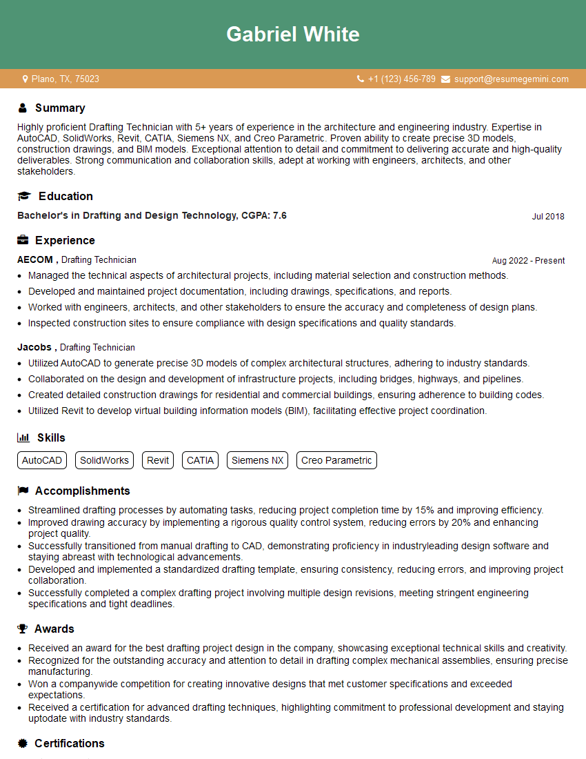
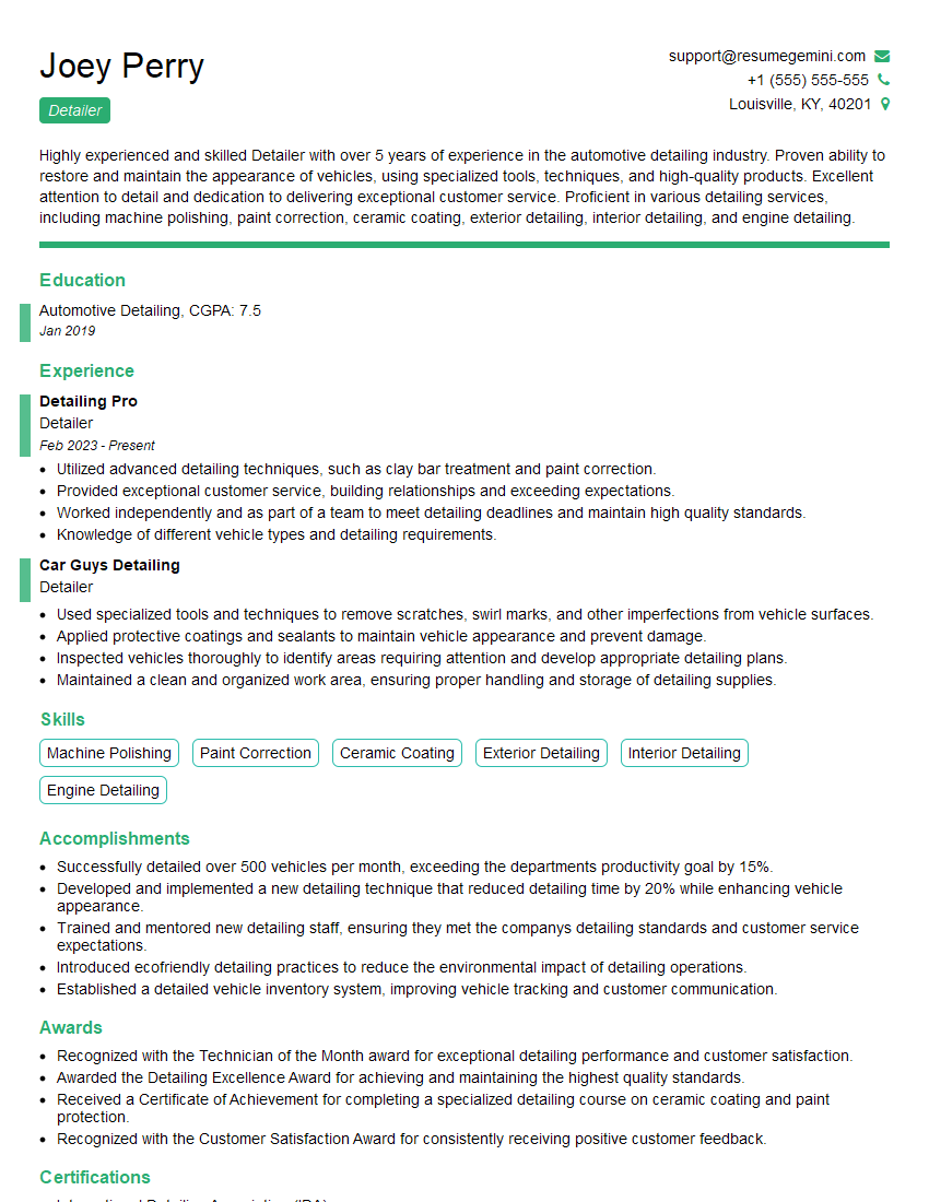
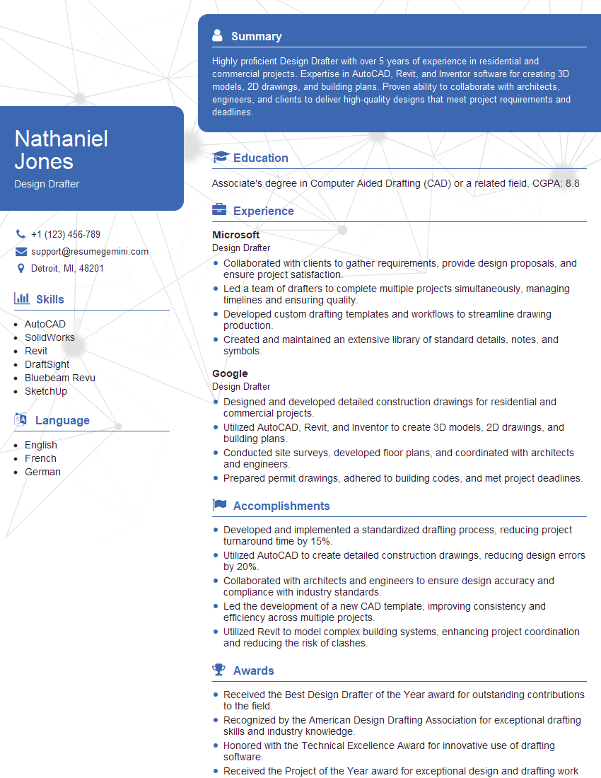
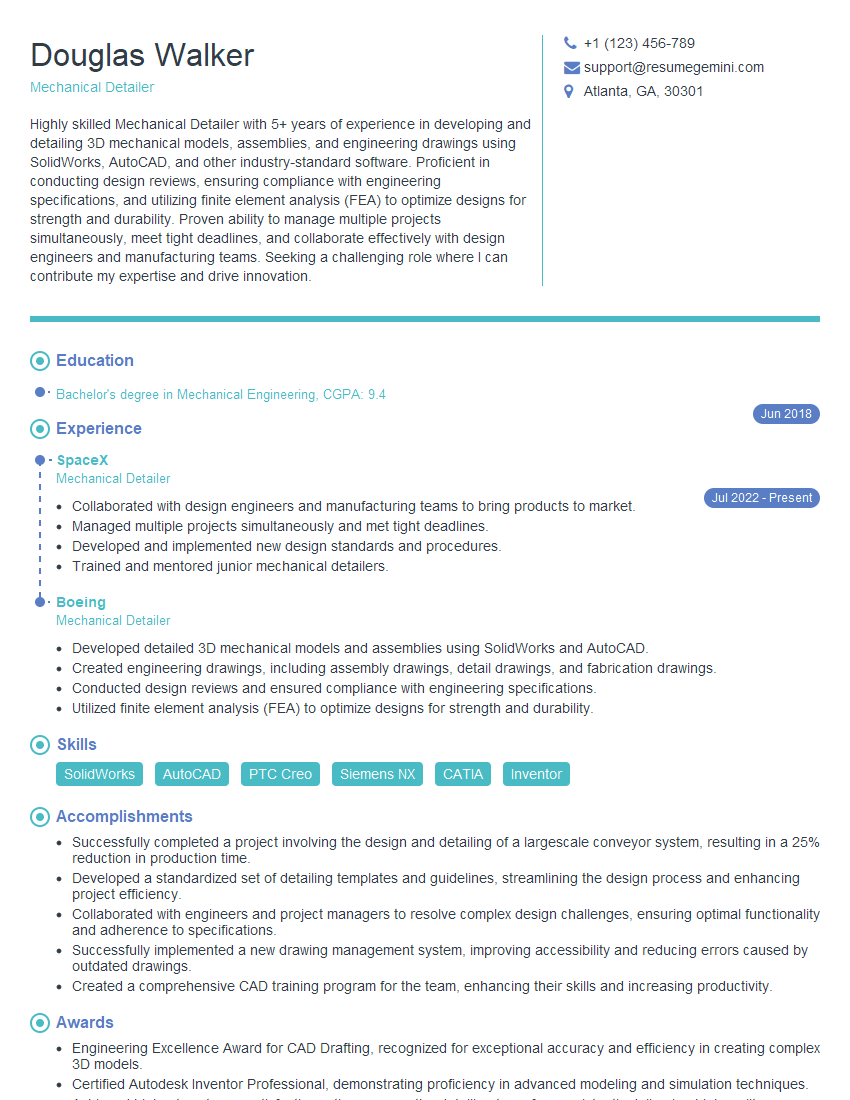
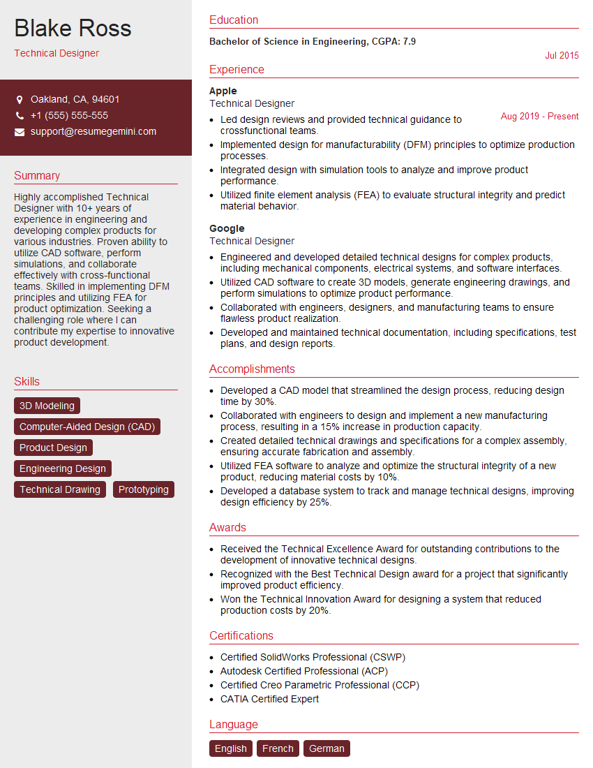
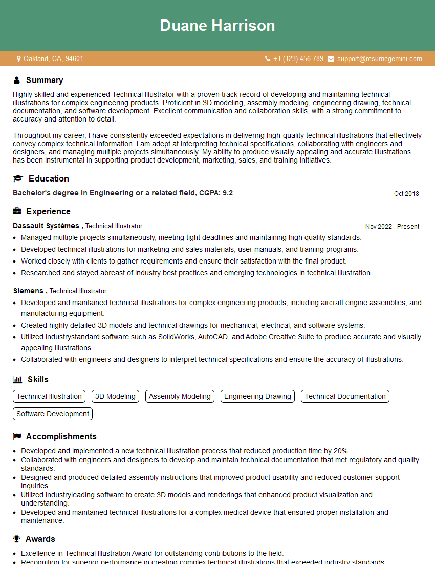
Mastering Detailing and Assembly Drawings is paramount for career advancement in engineering, manufacturing, and related fields. It directly impacts your ability to communicate technical information effectively and contribute to successful project completion. To maximize your job prospects, create an ATS-friendly resume that highlights your skills and experience. ResumeGemini is a trusted resource that can help you build a professional and impactful resume. Examples of resumes tailored to Detailing and Assembly Drawings are available to guide you.
Explore more articles
Users Rating of Our Blogs
Share Your Experience
We value your feedback! Please rate our content and share your thoughts (optional).
What Readers Say About Our Blog
Very informative content, great job.
good