Every successful interview starts with knowing what to expect. In this blog, we’ll take you through the top Proficient in AutoCAD, SolidWorks, Inventor, and Revit interview questions, breaking them down with expert tips to help you deliver impactful answers. Step into your next interview fully prepared and ready to succeed.
Questions Asked in Proficient in AutoCAD, SolidWorks, Inventor, and Revit Interview
Q 1. Explain your experience with AutoCAD’s command line interface.
AutoCAD’s command line interface (CLI) is the backbone of efficient drafting. It allows for rapid execution of commands without relying solely on the graphical user interface (GUI). My experience spans years of using the CLI for tasks ranging from simple line creation to complex geometric constructions. I find it particularly useful for scripting repetitive tasks and achieving greater precision. For example, instead of clicking and dragging to create a line, I can use the command LINE followed by coordinate inputs for precise placement. This method is significantly faster for repetitive tasks, especially when dealing with intricate designs.
Beyond basic commands, I’m proficient in using various modifiers like @ for relative coordinates, < for polar coordinates, and understanding the nuances of options within commands like CIRCLE (e.g., specifying radius or diameter). Mastering the CLI has substantially improved my drawing speed and accuracy, allowing me to handle large and complex projects with greater ease.
Q 2. Describe your proficiency in creating 2D drawings in AutoCAD.
Creating 2D drawings in AutoCAD is my bread and butter. My proficiency encompasses a wide range of tasks, from simple sketches to detailed technical drawings adhering to industry standards. I'm adept at using various tools to achieve precise geometric constructions, including lines, arcs, circles, splines, and polylines. I understand the importance of layering, dimensioning, text annotation, and creating accurate scales. I regularly use tools like the ARRAY command for creating repetitive elements and the TRIM and EXTEND commands for precise editing. For example, I recently created detailed shop drawings for a custom staircase, meticulously annotating dimensions, material specifications, and fabrication details, all in accordance with client requirements and relevant building codes.
Beyond the basics, I’m skilled in utilizing advanced features such as hatching patterns for surface representation, creating and managing external references (XREFs), and generating detailed schedules and reports.
Q 3. How do you manage layers and blocks effectively in AutoCAD?
Effective layer and block management is crucial for maintaining organization and efficiency in AutoCAD. I meticulously organize layers based on object types (e.g., architecture, structure, MEP), and assign appropriate colors and linetypes for quick visual identification. This allows for easy selective editing and plotting, avoiding conflicts and enhancing workflow. My approach is to keep the layer structure logical and intuitive, employing a naming convention that clearly reflects the layer's purpose. For instance, instead of generic names like “Layer1,” I would use descriptive names like “Walls-Exterior” or “Plumbing-Pipes.”
Regarding blocks, I create and utilize them extensively for repetitive components. This not only saves time but also ensures consistency across the drawing. I regularly attribute data to blocks (attributes) to manage and extract information such as part numbers, sizes, and material specifications. For instance, I've created custom blocks for standard door and window types, simplifying the drawing process considerably and maintaining uniform representation. Properly naming and organizing blocks in a library structure is equally essential for easy retrieval and reuse.
Q 4. Explain your experience with SolidWorks' Part, Assembly, and Drawing modules.
My experience with SolidWorks encompasses all three core modules: Part, Assembly, and Drawing. In the Part module, I'm proficient in creating complex 3D models using a variety of features, including extrudes, revolves, sweeps, and lofts. I'm comfortable working with different modeling techniques, adapting my approach based on the project's complexity and requirements. I frequently utilize features like patterns, mirrors, and shell to create efficient and accurate models.
The Assembly module allows me to combine individual parts into functional assemblies. I understand the importance of constraints and mates in defining relationships between parts, ensuring accurate movement and assembly behavior. I’m adept at managing large assemblies, using techniques such as component suppression and top-down assembly modeling to streamline the design process. For example, I recently assembled a complex robotic arm, ensuring all joints functioned correctly through precise constraint definition and simulation.
Finally, the Drawing module allows me to generate detailed 2D drawings from my 3D models. I'm proficient in creating orthographic views, sectional views, and detailed annotations, including dimensions, tolerances, and material specifications. I'm particularly attentive to creating clear and unambiguous drawings that meet industry standards.
Q 5. How familiar are you with SolidWorks' Simulation tools?
I have significant familiarity with SolidWorks Simulation tools. While I'm not a dedicated FEA (Finite Element Analysis) engineer, I have used these tools extensively for validating designs and predicting component behavior under various loads and conditions. I can perform basic static and dynamic simulations, assessing stress, strain, and deflection. For instance, I utilized SolidWorks Simulation to analyze the structural integrity of a custom bracket under load, optimizing its design to prevent failure.
My understanding extends to interpreting simulation results and making informed design modifications based on the findings. I'm aware of the importance of meshing and boundary condition settings in ensuring accurate simulation outcomes.
Q 6. Describe your workflow for creating and managing large assemblies in SolidWorks.
Managing large assemblies in SolidWorks requires a structured approach. My workflow focuses on modularity and efficient component organization. I start by breaking down the assembly into smaller, manageable sub-assemblies. This simplifies the assembly process and allows for easier troubleshooting. I heavily utilize top-down design techniques, starting with the overall assembly structure and progressively detailing individual components. I thoroughly document the design process, using configuration management tools provided by SolidWorks to track and manage revisions.
Furthermore, I leverage SolidWorks' tools for managing large assemblies such as component suppression, lightweight components, and external references. I also employ strategies like using simplified representations for components that aren't critical in a given context to improve overall performance. For example, when working with an assembly involving thousands of parts, I would replace less critical parts with simplified representations during design reviews, significantly improving performance without sacrificing accuracy.
Q 7. Explain your experience with Inventor's parametric modeling capabilities.
Inventor's parametric modeling capabilities are a powerful tool for creating flexible and robust designs. I'm highly proficient in using parameters to define and control various aspects of my models. This allows for easy design modifications and ensures consistency across multiple components. Changes made to a single parameter automatically update related features and components throughout the model. This is particularly useful when iterating on designs or making changes based on new specifications. For instance, I might define a parameter for overall length and use it to drive the dimensions of multiple parts in an assembly.
Beyond basic parameters, I understand the use of equations and iLogic for automating tasks and creating more complex design relationships. This allows for greater control and flexibility in creating dynamic and adaptable models. I've utilized these capabilities extensively in various projects, reducing errors and improving design efficiency. For instance, a recent project involved creating a custom jig for manufacturing. Using parameters and equations, I could easily adjust the jig dimensions based on variations in the workpieces without having to manually adjust each individual component.
Q 8. How do you handle constraints and relationships in Inventor?
Inventor's constraint system is incredibly powerful, allowing for precise and robust design. Constraints define relationships between geometric elements, ensuring that modifications to one part automatically update related parts. Think of it like assembling a model kit – constraints are the glue that holds everything together.
There are various types, including geometric constraints (e.g., mate, concentric, tangent), dimensional constraints (e.g., distance, angle, diameter), and insert constraints. For instance, you might use a 'mate' constraint to join two faces perfectly, a 'concentric' constraint to align two circles, or a 'distance' constraint to specify the gap between two parts.
Consider designing a simple bracket. You'd use constraints to fix the bracket's mounting holes to specific dimensions, ensuring the holes are precisely positioned relative to each other and other features. If you later decide to change the overall size, the constraints automatically adjust the positions of the mounting holes, maintaining the intended relationships.
Inventor also offers powerful tools for managing constraints, including constraint solvers that automatically resolve conflicts and identify under-constrained or over-constrained situations. It's essential to use constraints effectively to create stable and reliable designs that can be easily modified.
Q 9. Describe your workflow for creating detailed drawings in Inventor.
My workflow for creating detailed drawings in Inventor typically involves these key steps:
- Part Modeling: I begin with thoroughly modeling all parts, ensuring accuracy and incorporating all necessary features. This step lays the foundation for accurate drawings.
- Assembly Modeling: I then assemble the parts, validating the design and ensuring proper fit and functionality. This is crucial for understanding relationships and potential interference.
- Drawing Creation: I create a new drawing file and select the appropriate assembly or part. Inventor's automatic projection tools simplify this greatly. I strategically select views (isometric, orthographic, section views etc.) that clearly communicate the design intent.
- Dimensioning and Annotation: This is where I precisely dimension the components and add annotations like notes, tolerances, materials, and surface finishes. Clear and concise annotations are vital for manufacturing.
- Bill of Materials (BOM): I generate a BOM directly from the assembly model, ensuring an accurate list of parts and quantities. This saves time and reduces errors.
- Review and Revision: Before finalizing, I thoroughly review the drawing to verify accuracy and completeness. This step involves checking dimensions, annotations, and overall clarity. Any revisions are tracked and incorporated.
For example, when designing a complex gear system, I would create individual part models for each gear, then assemble them. The drawings would show detailed views of each gear, critical dimensions for tooth profiles, and annotations for material specifications and surface finishes. The BOM would list each gear, its material, and quantity needed for assembly.
Q 10. Explain your experience with Revit's family creation and management.
Revit's family creation is central to its parametric modeling approach. Families are essentially templates for re-usable components – think of them as standardized building blocks. I have extensive experience in creating both system families (e.g., walls, floors, roofs) and loadable families (e.g., doors, windows, furniture).
The process begins with understanding the parameters needed to define the family's behavior. For instance, a door family might require parameters for width, height, swing direction, and material. I use parameters to drive the geometry, ensuring consistent behavior and simplifying modifications. Family management involves organizing families in a structured library, adhering to naming conventions, and regularly updating families to reflect design changes or improved performance.
For example, when creating a custom window family, I carefully define parameters such as width, height, and mullion spacing. This allows for creating multiple window variations simply by changing the parameter values without redrawing the entire family. Maintaining a well-organized library is vital for project efficiency. Poorly managed families can lead to inconsistencies and errors.
Q 11. How familiar are you with Revit's collaboration features?
Revit's collaboration features are paramount for efficient teamwork on large projects. I'm highly familiar with using Revit Server and BIM 360 to manage central models and coordinate work between multiple users. This allows teams to work concurrently on different aspects of a building model without overwriting each other's changes.
We employ 'worksharing' to divide tasks among team members. Each user works on their designated portion of the model, and changes are regularly synchronized. Clash detection becomes significantly more important and efficient with worksharing. The version control helps track revisions and manage changes throughout the project lifecycle. Effective communication and clear project coordination protocols are critical for successful collaboration.
Imagine a large hospital project. Different teams handle architectural, structural, MEP (mechanical, electrical, plumbing), and fire protection design. Revit's collaboration tools facilitate seamless coordination, minimizing costly clashes and ensuring a well-integrated design.
Q 12. Describe your experience with creating and managing Revit schedules and quantities.
Revit schedules provide automated summaries of project information. They are crucial for quantity takeoffs, cost estimations, and documentation. I have considerable experience creating and managing various schedules, such as material takeoffs, door schedules, and equipment schedules. They automate data extraction from the model, removing the need for manual calculations, leading to greater accuracy and efficiency.
Quantity calculation through schedules is one of the major advantages over manual processes. For example, generating a schedule for doors automatically calculates the total number of each door type, sizes, and material. This reduces errors inherent in manual counting and spreadsheets. Customizing schedules to include specific parameters allows for detailed analysis. For instance, I might create a schedule detailing the total length of specific pipe sizes in an MEP system, providing valuable data for material procurement.
Proper schedule management is essential. This includes defining clear parameters, consistent naming conventions, and ensuring data accuracy. Regular review and updates maintain their relevance throughout the project lifecycle. Poorly managed schedules can lead to inaccurate estimations and significant project delays.
Q 13. How do you manage clash detection in Revit?
Clash detection in Revit is a critical process for identifying conflicts between different disciplines in a building model. For example, detecting where a ductwork system intersects a structural beam. Revit's built-in clash detection tools analyze the model to identify geometrical conflicts between different elements. I'm proficient in using these tools to run clash detection analyses, identifying and resolving such clashes before construction begins. This prevents costly rework on-site.
The process involves defining clash detection rules based on criteria such as proximity, element types, and criticality levels. The results are often presented visually, highlighting areas of conflict. The team then uses this information to review the design, make necessary modifications, and resolve the clashes. This iterative process ensures that the final design is free of significant interferences. Regular clash detection is vital throughout the project's lifecycle, with analyses run at key milestones to catch and resolve potential issues early.
The impact of effective clash detection is immense. By proactively identifying and resolving clashes during the design phase, projects can significantly reduce costly rework, delays, and potential safety hazards during construction.
Q 14. Compare and contrast AutoCAD, SolidWorks, Inventor, and Revit.
AutoCAD, SolidWorks, Inventor, and Revit are all powerful design software, but they serve different purposes:
- AutoCAD: Primarily 2D drafting, widely used for creating precise 2D drawings for various applications. It's excellent for detailed plans, elevations, and sections but has limited 3D modeling capabilities.
- SolidWorks: A 3D parametric modeling software focusing on mechanical design. It excels at creating complex parts and assemblies, featuring robust simulation and analysis tools. SolidWorks is less suited for architectural or building information modeling.
- Inventor: Also a 3D parametric modeling software, similar to SolidWorks in its capabilities but integrated with Autodesk's broader product ecosystem. It offers strong features for digital prototyping and detailed drawing creation.
- Revit: A Building Information Modeling (BIM) software designed specifically for architectural, structural, and MEP engineering. Its strength lies in collaborative design, creating intelligent models that contain comprehensive building data. While it has 3D modeling capabilities, its primary focus isn't on the detail level of mechanical parts like SolidWorks or Inventor.
Think of it this way: AutoCAD creates the blueprint, SolidWorks and Inventor design the machine parts, and Revit designs the building the machine will be in.
Each software has its strengths and weaknesses, and choosing the right tool depends heavily on the specific project requirements. I am proficient in all four, allowing me to leverage the most suitable software for any task.
Q 15. What are the limitations of each software package?
Each CAD software package, while powerful, has its strengths and limitations. Think of them like specialized tools in a toolbox – each best suited for certain tasks.
- AutoCAD: Excellent for 2D drafting and detailed drawings, but its 3D modeling capabilities, while present, are less intuitive and robust than dedicated 3D modelers like SolidWorks or Inventor. It can struggle with very large, complex assemblies.
- SolidWorks: A powerhouse for 3D modeling, particularly for mechanical design. However, it's less suited for architectural or civil engineering projects. Its rendering capabilities are good but may not match specialized rendering software.
- Inventor: Similar to SolidWorks in its 3D modeling strength, Inventor excels in creating detailed assemblies and managing complex parts. It's less intuitive for freeform surface modeling compared to some other software.
- Revit: Specifically designed for Building Information Modeling (BIM), Revit shines in architectural, structural, and MEP (Mechanical, Electrical, Plumbing) design. It's not ideal for detailed mechanical component design or intricate freeform shapes.
In essence, choosing the right software depends heavily on the specific project requirements. For example, you wouldn't use Revit to design a tiny watch component, nor would you use AutoCAD to model a high-rise building – though both are possible, the efficiency would be drastically reduced.
Career Expert Tips:
- Ace those interviews! Prepare effectively by reviewing the Top 50 Most Common Interview Questions on ResumeGemini.
- Navigate your job search with confidence! Explore a wide range of Career Tips on ResumeGemini. Learn about common challenges and recommendations to overcome them.
- Craft the perfect resume! Master the Art of Resume Writing with ResumeGemini's guide. Showcase your unique qualifications and achievements effectively.
- Don't miss out on holiday savings! Build your dream resume with ResumeGemini's ATS optimized templates.
Q 16. Describe a complex design problem you solved using CAD software.
I was tasked with designing a complex robotic arm for a manufacturing process. The challenge lay in creating a design that was both functional and space-efficient, incorporating several degrees of freedom and minimizing interference between moving parts. Using SolidWorks, I began by creating individual components – the base, links, joints (using custom designed parts for unique functionalities), and the end effector.
The complexity arose from the need for precise kinematic analysis. I leveraged SolidWorks' simulation tools to check for collisions and range of motion. Several iterations were necessary; for instance, early designs showed significant interference issues, requiring me to redesign certain joint mechanisms.
I employed parametric modeling extensively, allowing for easy modifications and ensuring consistent design updates across all parts. Finally, I created detailed assemblies, utilizing SolidWorks' assembly features for efficient management of the numerous components. The result was a highly functional, space-saving robotic arm design that met all performance requirements, successfully improving the manufacturing line's efficiency.
Q 17. What is your experience with rendering and visualization in CAD software?
My experience with rendering and visualization spans across all four software packages. Each has its own approach.
- AutoCAD: Rendering in AutoCAD is more basic, often relying on simple shading and line weights. I've used it primarily for creating clear, technical renderings focused on dimensions and annotations.
- SolidWorks: SolidWorks offers photorealistic rendering using its integrated rendering tools. I've extensively used these capabilities to create marketing materials and presentations, showing the design in a more appealing way to clients.
- Inventor: Similar to SolidWorks, Inventor provides good rendering tools, and I've employed them to create realistic simulations of assemblies in motion for client review.
- Revit: Revit's rendering capabilities are strong, especially for architectural visualization. I've used them to create walkthroughs and high-quality images showcasing building designs to stakeholders. For extremely detailed renderings, I often export from Revit to external rendering software such as Lumion or Enscape.
Beyond the software's inherent capabilities, I'm adept at post-processing rendered images to enhance their visual appeal using external image editing software.
Q 18. How do you ensure the accuracy and precision of your CAD models?
Accuracy and precision are paramount in CAD modeling. My approach involves several key strategies.
- Precise Input: I always use precise measurements and units throughout the modeling process, avoiding estimations. I carefully check the model's geometry using the software's measurement tools to verify dimensions and tolerances.
- Constraints and Relations: I heavily utilize parametric modeling and constraints to define relationships between model elements. This ensures that changes to one part automatically update related components, maintaining consistency and preventing errors.
- Regular Checks: Throughout the design process, I perform regular checks for geometric errors, such as gaps, overlaps, and inconsistencies. Software tools like interference detection and analysis features are crucial in this regard.
- Reference Models: When applicable, I use accurate reference models or drawings to guide the design and ensure fidelity to the intended specifications.
- Tolerance Analysis: For complex designs or critical applications, I perform tolerance analysis to understand and minimize the impact of manufacturing variations on the final product.
Essentially, it's a systematic approach, combining careful input with robust software functionality, to maintain the highest possible level of accuracy.
Q 19. Describe your experience with CAD data management and version control.
Effective CAD data management is crucial for collaborative projects and maintaining design integrity. My experience includes using various methods.
- Version Control Systems: I'm familiar with using cloud-based version control systems like Autodesk Vault and similar platforms. These allow for tracking changes, reverting to previous versions, and managing multiple revisions easily. They help avoid conflicts and ensure everyone is working with the most up-to-date files.
- File Naming Conventions: I consistently use a structured file-naming system including revision numbers, dates, and relevant identifiers. This ensures easy identification and organization of files.
- Data Backup Strategies: Regular backups are essential. I use both local and cloud-based storage to safeguard my CAD models from potential data loss.
- Data Transfer Protocols: I'm experienced in transferring large CAD files using secure and efficient methods, minimizing the risk of corruption.
Working efficiently and collaboratively requires a disciplined approach to version control and data management, ensuring data integrity and preventing costly errors.
Q 20. What are your preferred methods for creating detailed technical drawings?
Creating detailed technical drawings requires a blend of CAD skills and an understanding of engineering drawing standards. My approach is layered:
- Model-Based Drawings: I start with a well-defined 3D model as the foundation. This ensures that the drawings are always consistent with the design intent. The software will automatically update the drawings if changes are made to the model.
- Annotation and Dimensioning: I employ the software's annotation tools to precisely dimension all significant features, including tolerances, materials, and surface finishes, adhering strictly to relevant drafting standards (like ASME Y14.5).
- Views and Sections: I create appropriate views and sections to clearly illustrate all necessary features of the component or assembly.
- Bill of Materials (BOM): For assemblies, I generate a detailed BOM, listing all components and their quantities.
- Drawing Review and Revision: Before finalization, drawings are reviewed for completeness, accuracy, and clarity. Revisions are handled through version control systems, documenting all changes.
The goal is to create drawings that are not only precise and comprehensive but also easily understood by manufacturers and other stakeholders.
Q 21. Explain your understanding of different file formats used in CAD (e.g., DWG, DXF, IPT, IAM).
Understanding different CAD file formats is essential for interoperability and data exchange.
- DWG (Drawing): Autodesk's native format for AutoCAD. It's widely used and compatible with many other CAD programs but can sometimes lead to compatibility issues if different versions are involved.
- DXF (Drawing Exchange Format): A neutral file format that facilitates data exchange between different CAD systems. It's generally less feature-rich than DWG, sometimes losing some design information during conversion.
- IPT (Inventor Part): Inventor's native format for individual parts. These files contain all the design details and history of a single component.
- IAM (Inventor Assembly): Inventor's native format for assemblies, including relationships between multiple parts.
Choosing the appropriate file format depends on the intended use and recipient. For instance, DXF is preferred when exchanging data with users of different CAD systems, while IPT and IAM are used within the Inventor environment for retaining design history.
Q 22. How do you handle revisions and updates in your CAD projects?
Revision and update management in CAD is crucial for maintaining data integrity and collaboration. I employ a robust system combining version control, clear naming conventions, and change logs. Think of it like writing a document – you wouldn't just overwrite the entire thing each time; you'd use version control to track changes.
- Version Control: I leverage the built-in revision capabilities of each software package (AutoCAD's Xrefs and revisions, SolidWorks's data management tools, Inventor's iLogic or Vault integration, and Revit's worksharing and central model functionality). This creates a clear history of changes and allows easy rollback if necessary. For larger projects, dedicated Product Lifecycle Management (PLM) software is often integrated.
- Naming Conventions: A consistent naming system is key. I use a prefix indicating the revision number (e.g., RevA, RevB, RevC) followed by a descriptive name. This instantly communicates the model's status to anyone accessing it.
- Change Logs: A well-maintained change log documenting every alteration is essential. This should include the revision number, date, author, and a concise description of the changes. This is invaluable for traceability and auditing purposes.
For example, in a Revit project, worksharing allows multiple users to work on the model simultaneously, while the central model keeps track of revisions. If a conflict arises, the software provides tools to resolve it effectively.
Q 23. What are your strategies for optimizing CAD model performance?
Optimizing CAD model performance is vital for smooth workflow and preventing crashes. My strategies focus on simplifying geometry, managing file size, and utilizing software features to enhance efficiency.
- Geometry Simplification: I avoid unnecessarily complex geometry. Using simpler shapes where possible, employing appropriate levels of detail (LOD) based on the model's intended use (e.g., a low-poly model for rendering vs. a high-poly model for detailed analysis), and regularly purging unnecessary data significantly reduce file size and enhance performance.
- File Size Management: I regularly purge unused data, delete history, and compress files to keep them manageable. In SolidWorks, for example, I carefully manage design history to limit file bloat. Revit's Worksharing feature allows efficient management of large projects across multiple users.
- Software Features: Each software package provides optimization tools. AutoCAD's PURGE command removes unused objects, while Inventor's Content Center helps manage reusable components, reducing model complexity. Revit’s worksharing and family loading strategies are crucial for large-scale projects.
- Hardware Considerations: Sufficient RAM, a fast processor, and a solid-state drive (SSD) are essential for optimal performance. This is often overlooked but fundamental.
Imagine trying to edit a huge, poorly organized document. It's slow and frustrating. Similarly, a bloated CAD model hinders productivity.
Q 24. How familiar are you with scripting or automation in any of these software packages?
I'm proficient in scripting and automation using various languages within the CAD environments. This significantly improves efficiency and allows for customization beyond the software's standard features.
- AutoLISP (AutoCAD): I've written AutoLISP routines for automating repetitive tasks like generating drawings, extracting data, and creating custom tools. For instance, I wrote a script to automatically generate a title block with project-specific information.
- VBA (AutoCAD, SolidWorks, Revit): VBA (Visual Basic for Applications) is a powerful tool for automating tasks across multiple CAD platforms. I use it to create macros and integrate with other applications.
- Python (Inventor, Revit): Python is increasingly used for CAD automation, especially with Inventor and Revit’s API (Application Programming Interface). I've utilized Python to automate repetitive design tasks, such as generating variations of a component or analyzing model data.
Example: A Python script in Revit could automate the process of creating families based on user input, drastically speeding up the creation of repetitive elements.
#Example Python code (Illustrative) #This is a simplified example and requires the Revit API import clr clr.AddReference('RevitAPI') import Autodesk # ...rest of code to create family... Q 25. Describe your experience with using add-ins or extensions in CAD software.
Add-ins and extensions significantly enhance CAD software functionality, streamlining workflows and adding specialized capabilities. I've used numerous add-ins to boost my productivity and integrate with other platforms.
- AutoCAD: I've utilized add-ins for enhanced rendering, data extraction, and specialized design tools. For example, plugins offering advanced annotation tools or direct integration with point cloud data.
- SolidWorks: SolidWorks add-ins can provide functionalities such as advanced simulation tools, specialized surface modeling capabilities, or connectivity to PLM systems.
- Inventor: Inventor's add-ins expand capabilities related to simulation, rendering, and data management. Add-ins often improve the workflow by bringing in external data from other software.
- Revit: Revit add-ins dramatically enhance productivity. These can range from tools for better clash detection, improved visualization, or advanced parametric design capabilities. Many enhance data interoperability.
Selecting the right add-in is crucial. I carefully research and evaluate add-ins based on their functionality, reliability, and compatibility with my existing software versions and workflows.
Q 26. How do you approach troubleshooting issues in CAD software?
Troubleshooting CAD software issues requires a systematic approach. My strategy involves identifying the problem, isolating the cause, and applying the appropriate solution.
- Identify the Problem: Clearly define the issue. Is it a software crash, a rendering error, a geometric inconsistency, or a data corruption issue?
- Isolate the Cause: Try to reproduce the problem. Check the system logs for error messages, examine the model for inconsistencies, and test different parts of the model or workflow. A simple test model can often help to isolate the root cause.
- Apply the Solution: Once the root cause is identified, I apply the appropriate solution. This may involve repairing the model, reinstalling the software, updating drivers, changing hardware settings, seeking online resources (forums, documentation), or contacting technical support.
For example, a recurring crash might indicate a hardware limitation (insufficient RAM), a corrupted file, or a conflict with another software application. A systematic process allows me to pinpoint the underlying issue quickly.
Q 27. What methods do you employ for effective communication and collaboration on CAD projects?
Effective communication and collaboration are vital for successful CAD projects. I utilize a variety of tools and techniques to ensure seamless teamwork.
- Version Control Systems: Using version control (as discussed earlier) provides a shared platform for tracking revisions and changes, thus promoting collaborative editing and preventing conflicts.
- Cloud-Based Collaboration Platforms: Platforms like BIM 360 or similar services enable real-time collaboration, allowing multiple users to access and edit the same model simultaneously.
- Regular Meetings and Check-ins: I hold regular meetings or check-ins with team members to discuss progress, address challenges, and ensure everyone is on the same page. This is particularly important for large or complex projects.
- Clear Communication Protocols: Establishing a clear communication protocol helps to ensure everyone is aware of changes, deadlines, and responsibilities. This might involve using project management software, email, or instant messaging applications.
- Model Review and Feedback: I encourage regular model reviews and feedback sessions where team members can provide input and identify potential issues early in the design process.
Think of it like a well-orchestrated team sport: clear communication and coordination ensure a smooth and efficient process.
Q 28. Describe your experience in integrating CAD models with other software or platforms.
Integrating CAD models with other software and platforms is common practice. I frequently use various methods depending on the project's requirements and the software involved.
- Data Exchange Formats: I regularly export models to industry-standard formats like DWG, DXF, STEP, IGES, and FBX for interoperability with different software packages and platforms. This ensures seamless data exchange between different applications.
- Direct Integration: Some software packages offer direct integration with other applications. For example, I frequently use Revit's ability to import and link CAD files, or SolidWorks' integration with simulation software.
- APIs and Plugins: Using APIs (Application Programming Interfaces) and plugins allows for more sophisticated integration, enabling automation and data exchange between CAD software and other platforms such as project management or analysis software.
- Cloud-Based Platforms: Cloud platforms often provide convenient methods for sharing and collaborating on CAD models, allowing for easier integration with various software and platforms.
For instance, I’ve integrated a Revit model with a structural analysis software by exporting geometry in a suitable format, and then using the analysis results to inform design decisions within Revit.
Key Topics to Learn for Proficient in AutoCAD, SolidWorks, Inventor, and Revit Interview
- AutoCAD:
- Understanding 2D drafting principles and commands.
- Working with layers, blocks, and xrefs.
- Creating and manipulating complex drawings efficiently.
- Practical application: Detailing architectural plans or mechanical components.
- SolidWorks:
- 3D modeling techniques (part modeling, assembly modeling).
- Feature-based design and parametric modeling.
- Simulation and analysis tools (e.g., stress analysis).
- Practical application: Designing a mechanical part and simulating its functionality.
- Inventor:
- Understanding Autodesk Inventor's design environment and workflows.
- Creating and managing assemblies and sub-assemblies.
- Working with constraints and design parameters.
- Practical application: Designing a complex product assembly and creating detailed drawings.
- Revit:
- Building Information Modeling (BIM) principles and workflows.
- Creating and managing architectural, structural, and MEP models.
- Collaboration and coordination using Revit's collaborative features.
- Practical application: Developing a complete building model for construction documentation.
- General Proficiency:
- Understanding of design processes and best practices.
- Experience with data management and version control.
- Problem-solving skills in tackling design challenges.
Next Steps
Mastering AutoCAD, SolidWorks, Inventor, and Revit significantly enhances your career prospects in engineering and design. These software packages are industry-standard tools, and proficiency in them demonstrates valuable skills to potential employers. To maximize your job search success, creating an ATS-friendly resume is crucial. ResumeGemini is a trusted resource that can help you build a professional and impactful resume that stands out. We provide examples of resumes tailored to candidates proficient in AutoCAD, SolidWorks, Inventor, and Revit to guide you.

Project Engineer Resume Sample
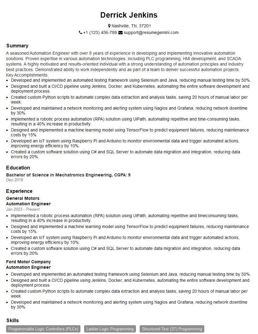
Automation Engineer Resume Sample
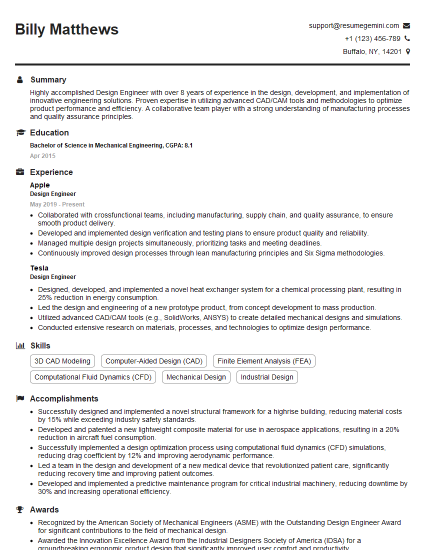
Design Engineer Resume Sample
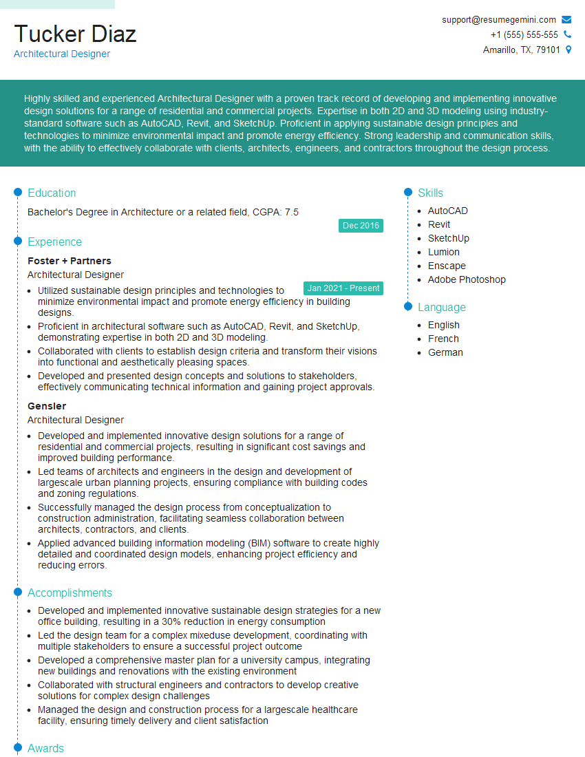
Architectural Designer Resume Sample
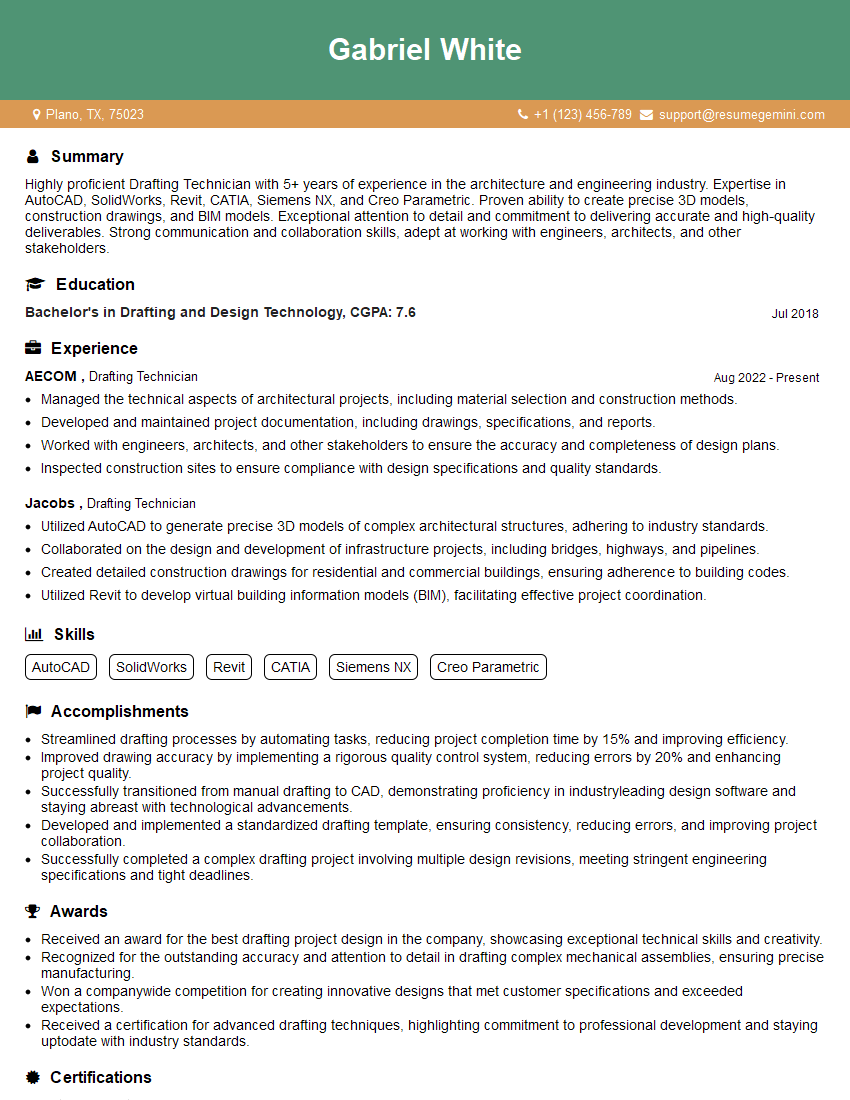
Drafting Technician Resume Sample
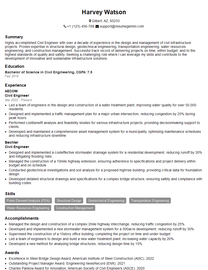
Civil Engineer Resume Sample
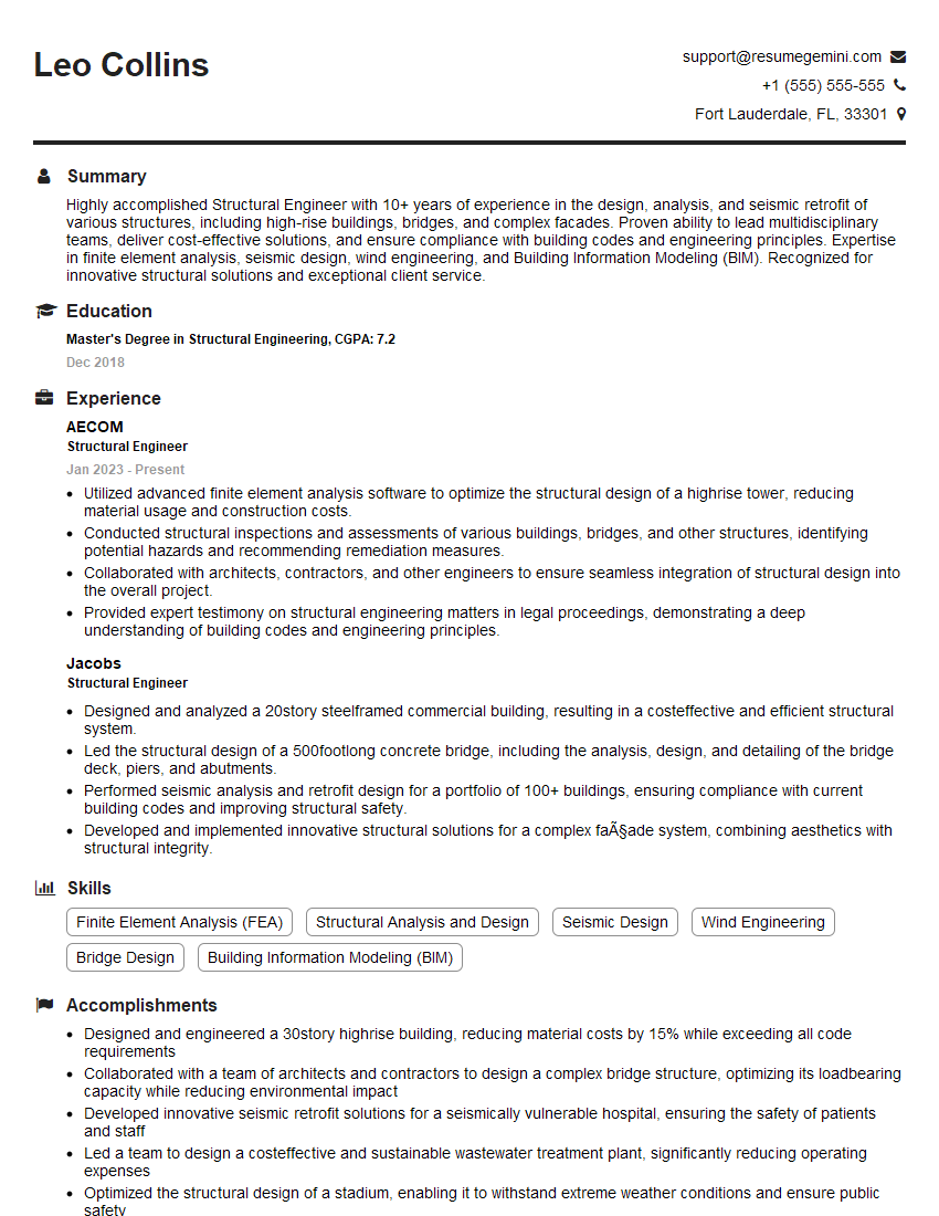
Structural Engineer Resume Sample
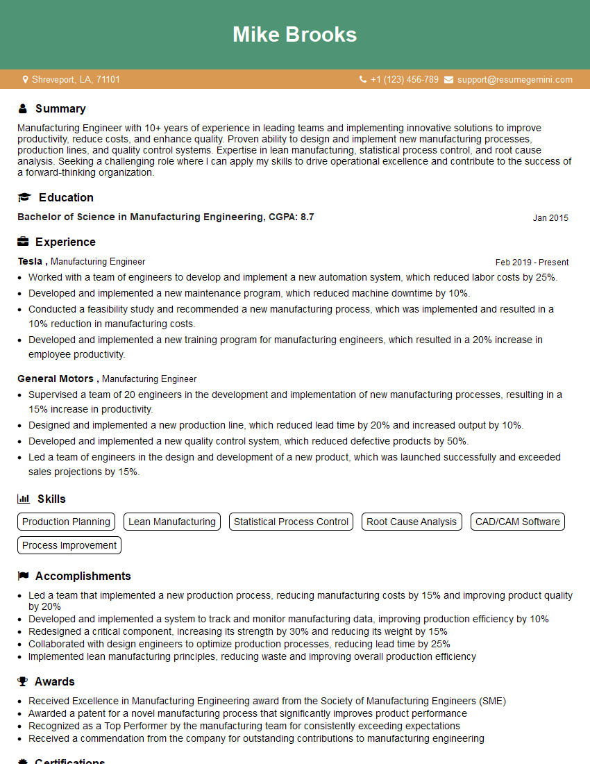
Manufacturing Engineer Resume Sample
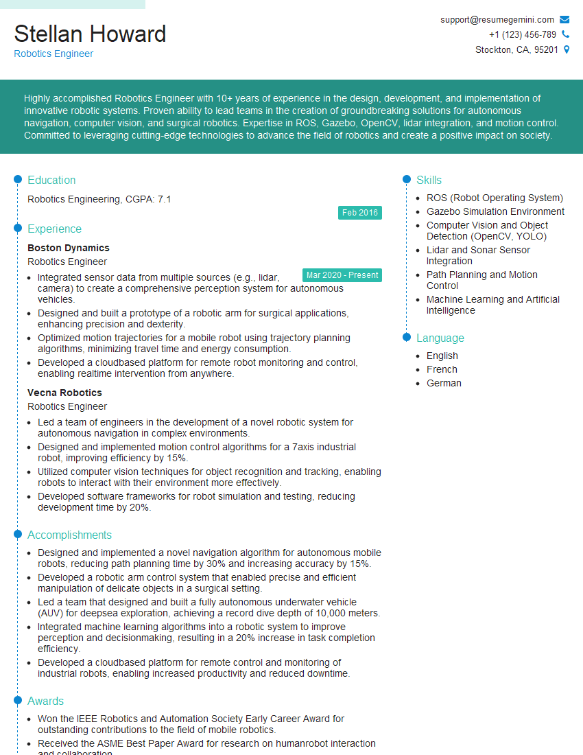
Robotics Engineer Resume Sample
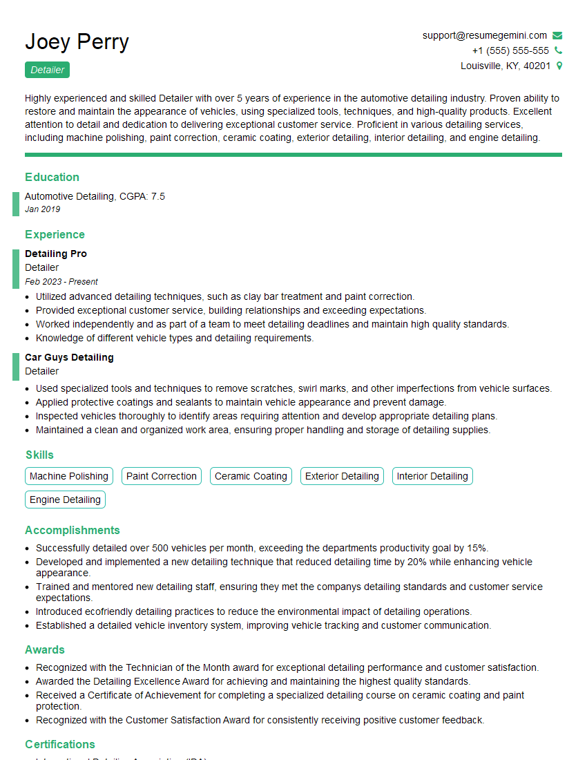
Detailer Resume Sample
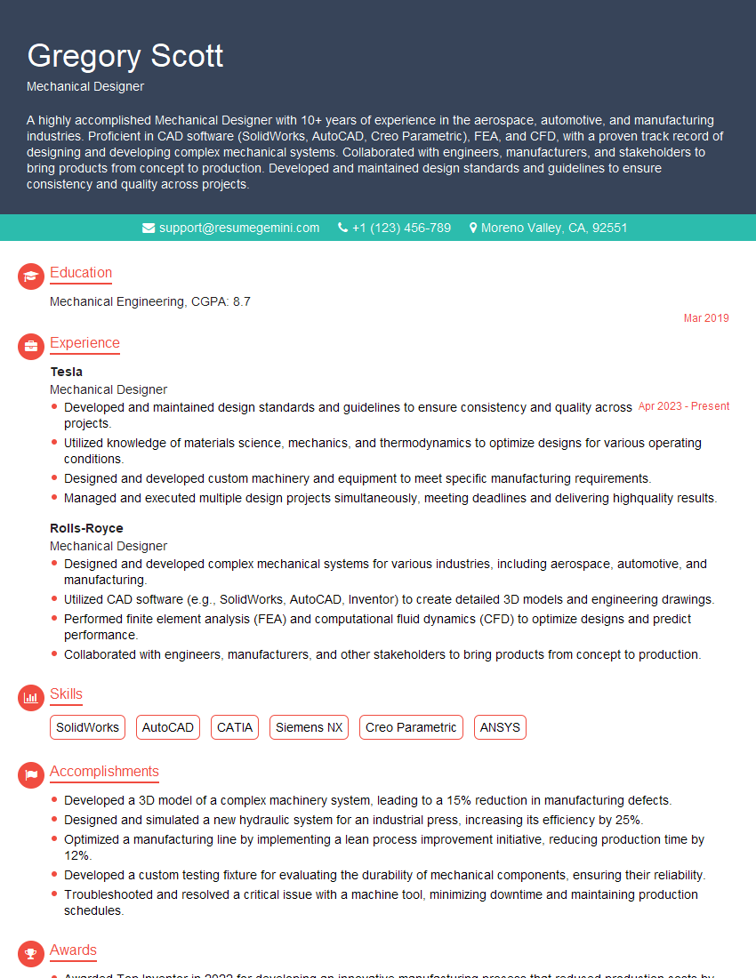
Mechanical Designer Resume Sample
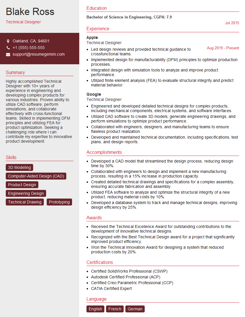
Technical Designer Resume Sample
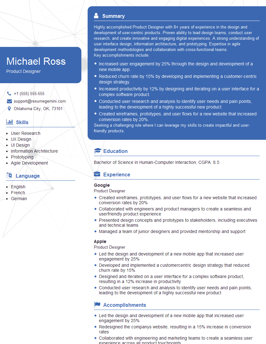
Product Designer Resume Sample
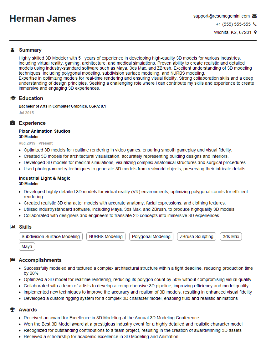
3D Modeler Resume Sample
Explore more articles
Users Rating of Our Blogs
Share Your Experience
We value your feedback! Please rate our content and share your thoughts (optional).
What Readers Say About Our Blog
Very informative content, great job.
good