Feeling uncertain about what to expect in your upcoming interview? We’ve got you covered! This blog highlights the most important Optical Fabrication interview questions and provides actionable advice to help you stand out as the ideal candidate. Let’s pave the way for your success.
Questions Asked in Optical Fabrication Interview
Q 1. Describe the process of polishing optical surfaces.
Polishing optical surfaces is the crucial final step in optical fabrication, aiming to achieve the desired surface figure and finish. It follows grinding, which removes significant material, leaving a relatively rough surface. Polishing refines this surface to an extremely smooth, precise shape, minimizing scattering and maximizing transmission or reflection.
The process typically involves using progressively finer abrasives, from coarse to extremely fine. This might include a sequence of laps (a polishing tool) with different abrasive compounds, like cerium oxide or pitch polishers. The choice of abrasive depends on the material being polished and the desired surface quality. The lap itself might be made of pitch, polyurethane, or other materials, each with different properties affecting the polishing rate and surface finish.
Imagine smoothing a piece of wood. You’d start with coarse sandpaper, then finer and finer grits, until you achieve a mirror-like finish. Optical polishing is similar, but on a microscopic scale, with extremely precise control required to meet demanding specifications.
Throughout the process, frequent measurements are made to monitor the progress and ensure the surface remains within tolerance. This often involves interferometry or other precise optical testing techniques.
Q 2. Explain the different types of optical coatings and their applications.
Optical coatings are thin layers of material deposited onto optical components to enhance their performance. They can modify reflectivity, transmission, or even polarization properties of light. Different coatings serve various purposes.
- Anti-reflection (AR) coatings: These reduce unwanted reflections at the surface of a lens or other optical element. They’re crucial for minimizing light loss and improving image contrast. A common example is the multilayer coating found on camera lenses, reducing glare and improving image quality.
- High-reflection (HR) coatings: These maximize reflection at a specific wavelength, making them essential for mirrors and other reflective components in lasers and other optical systems. Think of the highly reflective mirrors in a laser cavity.
- Dichroic coatings: These selectively transmit or reflect light of different wavelengths. They are used in many applications, such as color separation in projectors or filters for specific wavelengths in scientific instruments.
- Polarizing coatings: These control the polarization state of light, useful in applications like polarization microscopy or laser systems requiring specific polarization.
The choice of coating depends entirely on the application. For instance, a high-power laser mirror might require a highly durable, high-reflection coating, whereas an optical lens for a consumer product would need a more cost-effective anti-reflection coating.
Q 3. What are the common defects found in optical components, and how are they detected?
Several defects can occur during optical component fabrication. Detection methods vary depending on the defect type and severity.
- Surface scratches: These are imperfections on the surface that scatter light. They can be detected visually or using optical microscopes.
- Surface roughness: This refers to microscopic irregularities on the surface that affect scattering and reflectivity. Measured using surface profilometers or scattering techniques.
- Figure errors: Deviations from the desired surface shape, such as astigmatism or spherical aberration. Detected using interferometry.
- Internal inclusions: Bubbles or other imperfections within the material. These can scatter or absorb light. Detected visually or through scattering measurements.
- Stresses: Internal stresses in the material can affect the optical properties. Detected using polariscopes or photoelasticity techniques.
Advanced techniques like interferometry and scattering measurements are often combined to comprehensively assess the quality of optical components. The detection methods are critical for ensuring that the components meet the required specifications and performance.
Q 4. How do you ensure the accuracy of measurements in optical fabrication?
Ensuring accurate measurements is paramount in optical fabrication. It involves a combination of careful procedures and advanced metrology techniques.
- Calibration: All measuring instruments must be regularly calibrated against known standards, traceable to national or international standards organizations. This ensures the accuracy of the measurements.
- Environmental control: Temperature and humidity fluctuations can affect measurements. Controlled environments minimize these effects.
- Appropriate techniques: Selecting the right measurement technique is essential. For example, interferometry is often used for measuring surface figure, while profilometry measures surface roughness.
- Data analysis: Sophisticated software is used to analyze the measurement data and assess the accuracy of the results. Statistical methods can help identify and quantify uncertainties.
- Redundancy: Using multiple measurement techniques provides redundancy, improving confidence in the results. If different techniques yield consistent results, the accuracy is more assured.
The pursuit of accuracy often involves rigorous quality control protocols, with regular audits and checks to ensure consistency and reliability of measurements throughout the process.
Q 5. What are the different types of optical materials and their properties?
Optical materials are chosen based on their optical properties, mechanical strength, and cost. Here are some common types:
- Glass: Available in various types (e.g., BK7, fused silica), offering different refractive indices and dispersions. Fused silica is known for its excellent transmission across a broad wavelength range and high thermal stability.
- Crystals: Materials like calcium fluoride (CaF2) and zinc selenide (ZnSe) offer exceptional transmission in the infrared region, making them suitable for infrared optics.
- Polymers: Materials like PMMA (acrylic) and polycarbonate are less expensive but have lower scratch resistance and lower refractive indices compared to glass or crystals. Often used for less demanding applications.
The properties to consider include refractive index (how much the material bends light), dispersion (how the refractive index changes with wavelength), transmission (how much light passes through), and thermal expansion coefficient (how much the material changes size with temperature). The material choice significantly influences the optical performance and durability of the final component.
Q 6. Explain the principles of optical testing and metrology.
Optical testing and metrology involve precise techniques for measuring the properties of optical components and systems. The goal is to verify the component meets design specifications and performs as expected.
Principles: Many techniques rely on the principles of wave optics, analyzing the interference patterns produced by light interacting with the component. Interferometry is a cornerstone technique, using interference fringes to visualize surface irregularities, figure errors, or wavefront aberrations. Other methods include:
- Interferometry: Measures surface figure accuracy and wavefront aberrations using interference patterns.
- Scatterometry: Measures surface roughness and defects by analyzing scattered light.
- Profilometry: Uses physical contact or non-contact methods to measure surface topography.
- Transmission and reflection measurements: Used to evaluate transmission and reflection properties at various wavelengths.
Metrology in optical fabrication is essential to ensure high precision, quality control, and efficient production processes. Each technique provides specific information, and often a combination is employed for a complete assessment.
Q 7. Describe the process of generating aspheric surfaces.
Generating aspheric surfaces, surfaces that are not spherical, requires specialized techniques because they cannot be easily produced by conventional grinding and polishing methods used for spheres. These surfaces offer advantages in terms of aberration correction and improved optical performance compared to spherical lenses.
Several techniques are employed:
- Computer-controlled polishing: Using a computer-controlled polishing machine that can precisely adjust the tool’s shape and motion to achieve the desired aspheric form. This involves using specialized software and feedback from metrology systems to guide the polishing process.
- Diamond turning: A subtractive manufacturing process that uses a diamond tool to machine the aspheric surface on materials that can withstand the machining process. This is particularly well-suited for metals and some harder materials.
- Molding and replication: A cost-effective method for mass production. A master aspheric surface is created and then used to mold or replicate numerous copies.
The choice of technique depends on factors like the material, quantity needed, precision required, and cost considerations. The precision and control required for generating aspheric surfaces highlight the sophisticated technology needed in advanced optical fabrication.
Q 8. What are the challenges in fabricating freeform optics?
Fabricating freeform optics, unlike traditional spherical or aspherical lenses, presents unique challenges due to their complex, non-rotationally symmetric surfaces. These surfaces offer significant advantages in terms of performance, enabling miniaturization and improved light manipulation, but achieving the required precision is difficult.
- Manufacturing Complexity: Traditional machining techniques struggle with the intricate shapes. Specialized techniques like ultra-precision diamond turning or deterministic polishing are often necessary, requiring highly sophisticated equipment and skilled operators.
- Metrology Challenges: Accurately measuring the surface shape and figuring of freeform optics is incredibly demanding. Standard interferometry methods often fall short; advanced techniques like coordinate measuring machines (CMMs) and fringe projection profilometry are necessary, often requiring significant processing and analysis of measurement data.
- Material Selection: The choice of material greatly impacts the fabrication process. Certain materials are more amenable to specific manufacturing techniques; achieving the desired optical properties and surface finish can be challenging.
- Cost and Time: The complexity of design, machining, and metrology significantly increase the cost and time required to fabricate freeform optics compared to conventional optics.
For example, consider fabricating a freeform lens for augmented reality (AR) glasses. The lens must be extremely lightweight, compact, and have a complex surface profile to correct for various aberrations while minimizing distortion. This requires advanced diamond turning or polishing techniques coupled with precise metrology to verify the surface accuracy to nanometer levels.
Q 9. How do you handle the cleaning and handling of delicate optical components?
Cleaning and handling delicate optical components requires meticulous care to prevent damage that can compromise their performance. Even microscopic scratches or contamination can severely impact the optical quality. The key principles are cleanliness, gentleness, and proper handling procedures.
- Cleanroom Environment: All cleaning and handling should occur in a controlled environment, ideally a cleanroom, to minimize airborne particles and contamination. This reduces the risk of dust, fibers, or other contaminants adhering to the delicate surfaces.
- Appropriate Cleaning Agents: The choice of cleaning agents is critical. Isopropyl alcohol (IPA) is often used, but its concentration and application method should be carefully controlled to avoid residue or damage. Specialized cleaning solutions are available for different optical materials and coatings.
- Cleaning Techniques: Ultrasonic cleaning can be used to dislodge particles, followed by gentle rinsing with purified water and carefully controlled drying (e.g. nitrogen purge). Never rub aggressively; instead, use lint-free swabs or soft brushes.
- Handling Procedures: Always use clean gloves and proper handling tools, such as tweezers with soft tips or vacuum tools to avoid fingerprints and other contaminants. Components should be carefully supported to avoid stress or damage.
- Storage: Once cleaned, optics should be stored in protective containers or desiccant-filled cases to prevent moisture and dust accumulation.
I recall an instance where a seemingly insignificant fingerprint on a high-precision lens caused significant scattering and reduced the system’s performance by several orders of magnitude. This highlights the importance of strict cleanliness and handling protocols.
Q 10. Explain the difference between diamond turning and grinding in optical fabrication.
Diamond turning and grinding are both subtractive manufacturing processes used in optical fabrication, but they differ significantly in their techniques and applications.
- Diamond Turning: This is a single-point machining process that uses a very sharp, precisely controlled diamond tool to remove material from a rotating workpiece. It’s capable of producing very smooth, highly precise surfaces with extremely low surface roughness. It is particularly well-suited for generating aspherical and freeform optics from materials such as metals and some polymers.
- Grinding: This process uses abrasive particles to remove material from the optical surface. Multiple grinding stages with progressively finer abrasives are typically used to achieve the desired surface shape and roughness. Grinding is a more versatile technique applicable to a wider range of materials (glasses and crystals) but typically results in a rougher surface compared to diamond turning that requires further polishing.
The choice between diamond turning and grinding depends on the desired surface quality, material, and shape complexity. Diamond turning excels in creating highly precise aspheres and freeforms, while grinding is more suitable for large-scale, less demanding applications or as a pre-processing step before polishing.
For example, high-precision mirrors for astronomical telescopes might utilize diamond turning for the initial shaping and polishing to obtain a very smooth, reflective surface. Conversely, the primary lenses of a large optical system might initially be ground and then polished to achieve the necessary precision.
Q 11. What are the safety precautions necessary in an optical fabrication lab?
Safety in an optical fabrication lab is paramount due to the use of hazardous materials and equipment. A comprehensive safety program is essential.
- Eye Protection: Safety glasses or goggles should be worn at all times. Lasers and other intense light sources necessitate the use of appropriate laser safety eyewear.
- Hazardous Materials Handling: Proper handling and disposal procedures must be followed for chemicals like acids, solvents, and polishing compounds. Appropriate personal protective equipment (PPE), including gloves, lab coats, and respirators, is crucial.
- Machine Safety: All machinery, including grinding and polishing equipment, must be properly guarded and maintained. Workers should receive thorough training on the safe operation of all machinery and tools.
- Laser Safety: Lasers, if present, must be properly enclosed, and workers trained on appropriate safety protocols. Interlocks and warning systems must be functional.
- Housekeeping: Maintaining a clean and organized workspace reduces the risk of slips, trips, and falls. Proper waste disposal is essential to prevent environmental contamination.
Regular safety training and drills are crucial to ensure that all personnel are aware of and adhere to safety procedures. Each incident, however minor, needs investigation to determine the cause and implement corrective actions.
Q 12. Describe your experience with optical metrology equipment.
My experience with optical metrology equipment encompasses a wide range of instruments used to characterize the surface shape, roughness, and other optical properties of components. I’m proficient in operating and interpreting data from several key instruments.
- Interferometers: I’m highly experienced with various types, including Fizeau and Twyman-Green interferometers, for measuring surface irregularities and wavefront errors with nanometer precision. This includes understanding different types of fringes and their interpretation.
- Coordinate Measuring Machines (CMMs): I’ve extensively used CMMs to measure the 3D shape and dimensions of optical components, particularly useful for freeform surfaces that are challenging to characterize with interferometry.
- Profilometers: I’ve utilized contact and non-contact profilometers to determine surface roughness (Ra, Rz) and other surface texture parameters, providing crucial information about surface quality.
- Scatterometers: My experience includes using scatterometers to quantify the surface roughness and scattering properties of optical components.
I am adept at data analysis and interpretation, using specialized software to process metrology data and determine compliance with design specifications. I can identify and troubleshoot issues with metrology equipment and ensure its calibration and proper use.
Q 13. How do you ensure the quality control of optical components?
Quality control in optical fabrication is crucial to ensure that the final components meet the specified requirements. A multi-stage approach is used throughout the manufacturing process.
- Incoming Material Inspection: Raw materials are inspected to verify their properties and suitability for the intended application.
- Process Monitoring: Key process parameters are monitored throughout the fabrication process, including temperature, pressure, and machining parameters. This ensures consistent quality and helps prevent defects.
- Intermediate Inspections: Components undergo multiple inspections during the grinding, polishing, and coating stages. This helps detect and correct any deviations from specifications early in the process.
- Final Inspection: The final components undergo rigorous testing and metrology to verify their surface quality, optical performance, and compliance with design specifications. This includes tests for surface roughness, transmission, reflection, and wavefront aberrations.
- Statistical Process Control (SPC): SPC techniques are implemented to continuously monitor and improve the manufacturing process. This helps identify trends and potential problems before they lead to significant defects.
Documenting all inspection and testing results is critical for traceability and compliance with industry standards. Data analysis enables continuous improvement and helps identify areas for optimization. This detailed approach helps guarantee that only high-quality components are delivered.
Q 14. How do you troubleshoot problems during the optical fabrication process?
Troubleshooting in optical fabrication involves a systematic approach to identify and resolve problems that may arise during the process. It often requires a deep understanding of both the fabrication techniques and the optical properties of the materials.
- Identify the Problem: Begin by clearly defining the problem. Is it a surface defect, a dimensional error, or a change in optical performance? Detailed documentation of the process is crucial here.
- Analyze the Process: Review the process parameters, including the materials used, the machines involved, and the operator’s procedures. Look for variations from standard operating procedures.
- Isolate the Root Cause: Use various diagnostic techniques to isolate the root cause. This might include analyzing the metrology data, examining the surface using microscopy, or repeating certain process steps under controlled conditions.
- Implement Corrective Actions: Once the root cause has been identified, implement the necessary corrective actions. This could involve adjustments to the machine parameters, modification of the process steps, or replacement of defective materials.
- Verify the Solution: After implementing the corrective actions, verify that the problem has been solved and that the process is back in control. Repeat inspections and metrology checks to ensure consistent quality.
For example, if I encounter unexpected surface defects after polishing, I might investigate the polishing compound, the polishing pad, the pressure applied, or the dwell time. By systematically ruling out possible causes, I can pinpoint the exact problem and implement a solution.
Q 15. Explain your experience with different optical fabrication techniques.
My experience in optical fabrication spans a wide range of techniques, encompassing both traditional and advanced methods. I’ve worked extensively with generating aspheric surfaces using diamond turning, a process where a precisely controlled diamond tool removes material from a substrate to create highly accurate shapes. This is particularly useful for creating freeform optics with complex surfaces. I’m also proficient in precision grinding and polishing, the classic methods for creating high-quality spherical and aspherical lenses. This involves carefully selecting abrasives and controlling the polishing process to achieve the desired surface finish and accuracy. Furthermore, I have experience with chemical-mechanical polishing (CMP), a technique that uses a slurry of chemical and mechanical actions for planarization and achieving very smooth surfaces necessary for advanced applications. Finally, I’ve been involved in the fabrication of molded optics, which offer a cost-effective solution for high-volume production of simpler lens shapes.
For example, in a recent project involving the creation of a high-precision telescope lens, diamond turning was crucial for achieving the extremely smooth and accurate aspheric surface required for optimal performance. In contrast, for a mass-produced camera lens, molding proved the most efficient and cost-effective method.
Career Expert Tips:
- Ace those interviews! Prepare effectively by reviewing the Top 50 Most Common Interview Questions on ResumeGemini.
- Navigate your job search with confidence! Explore a wide range of Career Tips on ResumeGemini. Learn about common challenges and recommendations to overcome them.
- Craft the perfect resume! Master the Art of Resume Writing with ResumeGemini’s guide. Showcase your unique qualifications and achievements effectively.
- Don’t miss out on holiday savings! Build your dream resume with ResumeGemini’s ATS optimized templates.
Q 16. Describe your experience with computer-controlled optical surfacing machines.
I have extensive experience operating and programming computer-controlled optical surfacing machines, including CNC (Computer Numerical Control) machines and advanced ion beam figuring systems. These machines allow for highly precise and repeatable surface generation and modification. My expertise covers various aspects, including machine setup, programming using CAD/CAM software (like Zemax or Code V, which I’ll discuss later), process optimization for different materials, and quality control procedures. I’m comfortable working with both subtractive (removing material) and additive (depositing material) processes on these machines.
One particular challenge I overcame was programming a CNC machine to fabricate a freeform lens with a highly complex surface profile. This required a deep understanding of the machine’s capabilities, meticulous planning of the machining path, and rigorous testing to ensure accuracy. The result was a high-quality lens that significantly outperformed its conventionally manufactured counterparts.
Q 17. How do you interpret optical drawings and specifications?
Interpreting optical drawings and specifications is fundamental to my work. This involves understanding geometric tolerances (like surface flatness, radius of curvature, and center thickness), material specifications, optical coating requirements, and performance metrics (like wavefront error and transmission). I’m adept at using various standards like ISO 10110 to ensure that all specifications are clearly understood and adhered to during the fabrication process.
For instance, a typical drawing would include detailed dimensions, surface profiles (often specified by a mathematical equation or a series of data points), and surface quality specifications (e.g., scratch-dig specifications). I carefully review these drawings to identify potential challenges or conflicts, and to plan the fabrication process accordingly. Discrepancies or ambiguities are always flagged and clarified before proceeding.
Q 18. What software are you familiar with for optical design and simulation?
My proficiency extends to several optical design and simulation software packages. I’m highly experienced with Zemax OpticStudio, a powerful tool that I use for designing, analyzing, and optimizing optical systems. This includes performing tolerance analysis, assessing system performance under various conditions, and creating detailed manufacturing specifications. I’m also familiar with Code V, another industry-standard software known for its rigorous modeling capabilities. Additionally, I have experience using SolidWorks for 3D modeling and creating detailed manufacturing drawings.
In one instance, using Zemax, I simulated the performance of a new lens design under varying environmental temperatures. This simulation enabled me to identify and mitigate potential performance issues before proceeding with the costly fabrication process, resulting in substantial savings and improved quality.
Q 19. What is your experience with different types of optical adhesives and sealants?
My experience with optical adhesives and sealants encompasses a variety of materials, each chosen based on specific application requirements. These include UV-curable adhesives, epoxy resins, and silicone-based sealants. The selection depends on factors such as the materials being bonded (e.g., glass, metal, polymers), the required refractive index matching, the operating temperature range, and the need for optical clarity and stability. I am experienced in evaluating the chemical compatibility of different materials to prevent degradation or unwanted reactions.
For example, when bonding a delicate lens to a precision housing, I would carefully select a low-viscosity UV-curable adhesive to ensure complete filling of the gap without causing stress to the lens. Conversely, for applications requiring high temperature stability, I would opt for a specialized epoxy with a high glass transition temperature (Tg).
Q 20. How do you manage optical component inventory and tracking?
Effective optical component inventory and tracking is critical for maintaining efficiency and ensuring project success. I use a combination of barcoding, a dedicated database system, and specialized software for managing our inventory. Each component is uniquely identified, and its location, status (e.g., in-process, finished, tested), and relevant specifications are meticulously recorded. This enables accurate tracking of materials throughout the entire fabrication process, from raw materials to finished products, minimizing the risk of loss or misidentification.
The system also allows for real-time inventory monitoring, enabling us to efficiently plan procurement, reduce material waste, and promptly address any potential supply chain disruptions. Regular audits of the inventory system help ensure its accuracy and maintainability.
Q 21. Explain your experience with the fabrication of different types of lenses.
My experience in lens fabrication encompasses a broad spectrum of lens types, including spherical lenses (both singlet and achromatic doublets), aspheric lenses, cylindrical lenses, and freeform lenses. The fabrication techniques employed depend heavily on the lens type, desired precision, and volume. For example, spherical lenses are often produced using precision grinding and polishing, while aspheric lenses frequently require diamond turning or computer-controlled polishing. Freeform lenses present the most significant challenges due to their complex surface shapes, often requiring advanced CNC machining and specialized metrology to ensure the accuracy of the fabricated surface.
A particularly challenging project involved the fabrication of a high-power laser lens that required extremely stringent surface quality specifications. The successful completion of this project involved not only advanced fabrication techniques, but also precise control over the environment to minimize dust contamination and other factors that could negatively affect the lens’s performance.
Q 22. Describe your experience with the fabrication of mirrors and prisms.
My experience with mirror and prism fabrication spans over 10 years, encompassing various techniques from initial substrate preparation to final polishing and coating. I’ve worked extensively with different materials, including fused silica, Zerodur, and various types of glass. For mirrors, I’ve been involved in the entire process: starting with figuring (shaping the substrate to the desired curvature) using techniques like grinding and polishing with progressively finer abrasives. This involves careful control of the removal rate to achieve the desired surface figure and finish. For large, high-precision mirrors, we often utilize ion-beam figuring for precise surface control. Prism fabrication involves similar grinding and polishing techniques, but the focus shifts to achieving precise angles and surface flatness. We use angle measuring tools such as autocollimators to ensure accuracy to within arcseconds. I’ve also worked with specialized techniques for creating prisms with specific coatings for applications in laser systems or spectroscopy.
For example, in one project, we fabricated a large off-axis parabolic mirror for a solar telescope. The challenge was achieving a very smooth surface figure and minimizing surface irregularities (roughness) to maximize reflectivity. We used a combination of computer-controlled polishing and interferometric testing to ensure the final product met the stringent tolerances.
With prisms, I recall a project involving the fabrication of a series of right-angle prisms for a high-precision optical alignment system. Achieving the correct angles within tight tolerances was critical for the proper functioning of the system. We used a combination of diamond-turning and precision polishing to ensure the final products met the requirements.
Q 23. Explain your understanding of tolerance analysis in optical systems.
Tolerance analysis in optical systems is crucial for ensuring the final product performs as intended. It involves systematically identifying and quantifying the impact of manufacturing variations and environmental factors on the system’s overall performance. This is often performed using software packages capable of ray tracing and tolerancing. We consider factors such as surface figure errors, deviations in radius of curvature, wedge angle errors (in prisms), decentration errors, and tilt errors. The analysis usually involves a combination of statistical methods and Monte Carlo simulations to evaluate the effect of various error combinations.
The goal is to determine which tolerances are most critical and to optimize the design and manufacturing processes to minimize their impact. For example, a tighter tolerance on the radius of curvature of a lens might be more critical than a slightly looser tolerance on the surface roughness, depending on the specific application. A tolerance budget is created, allocating permissible error to different components of the optical system. Tolerance analysis helps to prevent costly rework or scrap by ensuring that the manufacturing specifications are realistic and achievable.
Q 24. How do you evaluate the surface roughness of optical components?
Surface roughness of optical components is evaluated using various techniques, primarily employing surface profilometers and atomic force microscopes (AFMs). Profilometers use a stylus to scan the surface and measure its height variations, providing a quantitative measure of roughness (Ra, Rq, etc.). AFMs offer much higher resolution, allowing us to measure nanometer-scale roughness. Interferometry is also used to assess surface quality, although it’s more sensitive to overall figure error rather than fine-scale roughness.
For instance, we might use a profilometer for assessing the roughness of a lens surface after polishing, ensuring it’s within the required range for minimal light scattering. For ultra-smooth surfaces needed in high-precision applications, an AFM would be necessary to characterize the surface at the nanoscale.
Scatterometry is another technique that indirectly evaluates surface roughness by measuring the angular distribution of scattered light. This method is often used in situ during the fabrication process for process monitoring and control. The choice of technique depends heavily on the desired resolution and the application of the component.
Q 25. What is your experience with thin-film deposition techniques?
My experience with thin-film deposition techniques is extensive, including physical vapor deposition (PVD) and chemical vapor deposition (CVD). I’m proficient in techniques like sputtering, e-beam evaporation, and ion-assisted deposition. These techniques allow for precise control over the thickness and optical properties of the deposited films. These coatings are crucial for enhancing the performance of optical components; for example, anti-reflection coatings minimize unwanted reflections, while high-reflectivity coatings maximize reflectivity in specific wavelength ranges. In addition, I’m experienced with the characterization of thin films using techniques like ellipsometry and spectrophotometry to verify the quality and performance of the deposited layers.
A specific example includes working on the development of a specialized broadband anti-reflection coating for a high-power laser system. The challenge here was balancing low reflectivity across a broad wavelength range while maintaining high laser-damage resistance. This required careful optimization of the deposition parameters and film composition. The resultant coating significantly improved the efficiency of the laser system by reducing energy loss due to reflections.
Q 26. Describe your knowledge of interferometry and its applications in optical metrology.
Interferometry is a powerful metrological technique used to measure surface figure, flatness, and other optical properties with extremely high precision. It leverages the interference patterns created when two coherent light beams overlap. In optical metrology, common techniques include Fizeau interferometry, Twyman-Green interferometry, and phase-shifting interferometry. These techniques provide quantitative data on the surface irregularities, allowing us to assess the quality of optical components during and after fabrication.
Fizeau interferometry, for instance, is frequently used for measuring the surface figure of flat optics and lenses. The interference pattern is analyzed to determine the deviations from an ideal surface. Phase-shifting interferometry enhances accuracy by introducing a controlled phase shift between the two interfering beams, allowing for a more precise determination of the surface profile.
Interferometry is indispensable in ensuring the quality of high-precision optics used in telescopes, laser systems, and lithographic equipment. For instance, the quality of a telescope mirror’s surface directly impacts its imaging performance. Interferometry allows us to precisely characterize and correct the mirror’s surface figure, thereby optimizing the telescope’s resolution.
Q 27. How do you calculate the power of a lens?
The power of a lens is determined by its ability to bend light, and it’s measured in diopters (D). The lens power (P) is the reciprocal of its focal length (f), expressed in meters: P = 1/f
For a thin lens in air, the focal length is related to the refractive index (n) of the lens material and the radii of curvature (R1 and R2) of its two surfaces by the Lensmaker’s equation:
1/f = (n-1) * (1/R1 - 1/R2)
Here, R1 and R2 are positive if the surface curves away from the incident light (convex) and negative if it curves towards the incident light (concave). So, to calculate the power, you first need to determine the focal length using the Lensmaker’s equation and then apply the formula P = 1/f. The resulting value will be in diopters.
For example, a biconvex lens made of glass (n ≈ 1.5) with R1 = 10 cm and R2 = -10 cm has a focal length of 10 cm or 0.1 m. Its power is P = 1/0.1m = 10D
Q 28. Explain the principles of diffraction and its effects on optical systems.
Diffraction is the phenomenon where light waves spread out after passing through an aperture or obstacle. This deviation from rectilinear propagation affects optical system performance, particularly at high spatial frequencies. Huygens’ principle explains diffraction—each point on a wavefront acts as a source of secondary spherical wavelets, and their superposition determines the resulting wavefield.
In optical systems, diffraction limits the resolution—the ability to distinguish between closely spaced objects. The Airy disk, a central bright spot surrounded by concentric rings, is the diffraction pattern produced by a point source focused by a lens. The Airy disk’s size determines the minimum resolvable distance between two point sources. Diffraction also causes blurring and loss of contrast in images.
Diffraction effects are particularly significant in high-resolution imaging systems, such as microscopes and telescopes. The design of these systems carefully considers diffraction effects to maximize resolution and minimize image degradation. Techniques like apodization (modifying the aperture shape) can help to manage diffraction effects. Understanding diffraction is essential for optimizing optical system design and performance.
Key Topics to Learn for Optical Fabrication Interview
- Optical Material Properties: Understanding the characteristics of various optical materials (e.g., glass, crystals, polymers) and their impact on lens performance. This includes refractive index, dispersion, and transmission properties.
- Fabrication Processes: Gain a strong grasp of different manufacturing techniques such as grinding, polishing, coating, and their associated challenges and quality control measures. Consider the practical implications of choosing one method over another for specific applications.
- Optical Testing and Metrology: Familiarize yourself with methods for measuring surface quality (e.g., interferometry, profilometry) and optical performance (e.g., transmission, reflection measurements). Be ready to discuss the significance of accurate testing in ensuring high-quality lenses and optical systems.
- Lens Design Principles (Basic): While not strictly fabrication, a foundational understanding of basic lens design concepts (e.g., focal length, aberrations) will enhance your ability to discuss the fabrication challenges associated with specific lens designs.
- Precision Measurement and Tolerances: Deeply understand the importance of precise measurements and tolerances in optical fabrication. Be able to discuss the impact of deviations from specified dimensions and surface quality on the final optical performance.
- Coatings and Thin Films: Learn about the various types of optical coatings (e.g., anti-reflection, high-reflection) and their deposition techniques. Understand how coatings affect the performance of optical components.
- Troubleshooting and Problem-Solving: Prepare to discuss common issues encountered during the fabrication process and your approach to identifying and resolving them. This demonstrates practical experience and analytical skills.
Next Steps
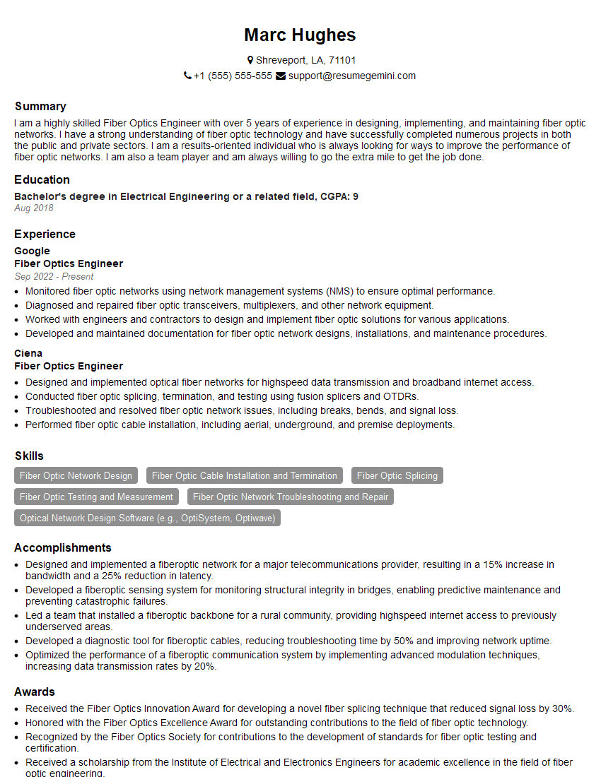
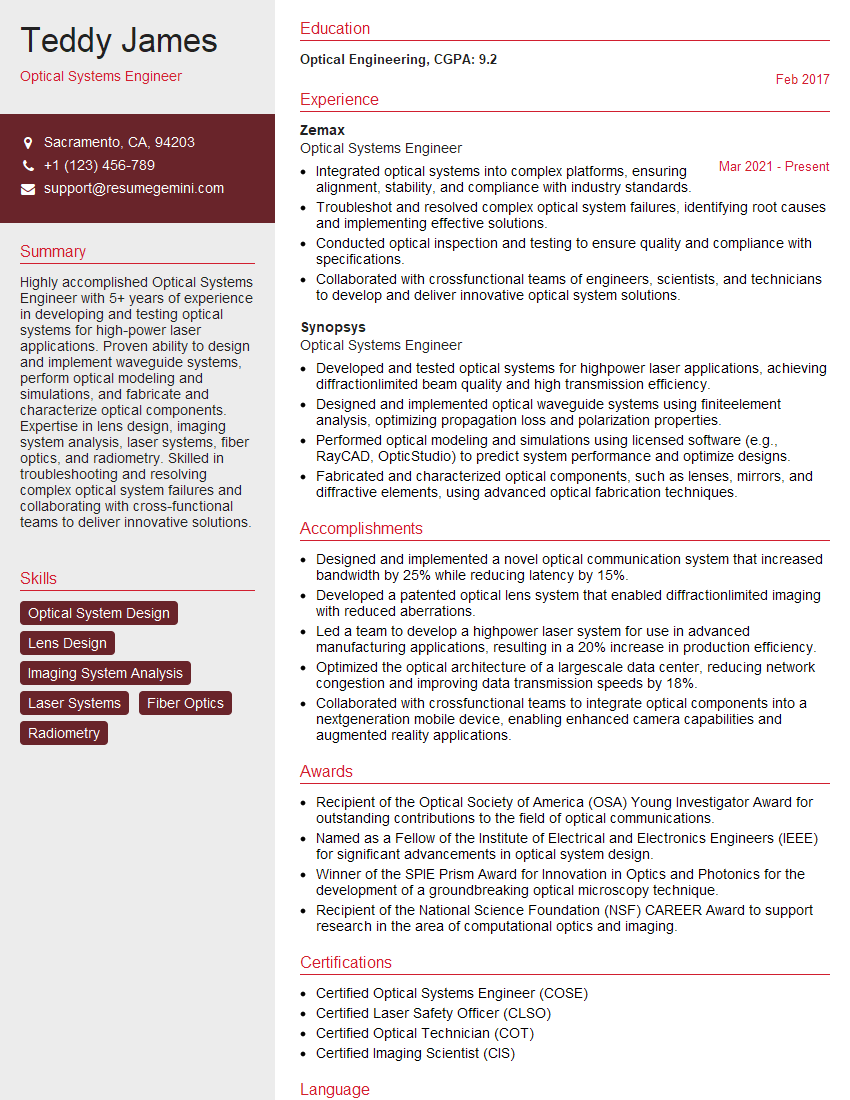
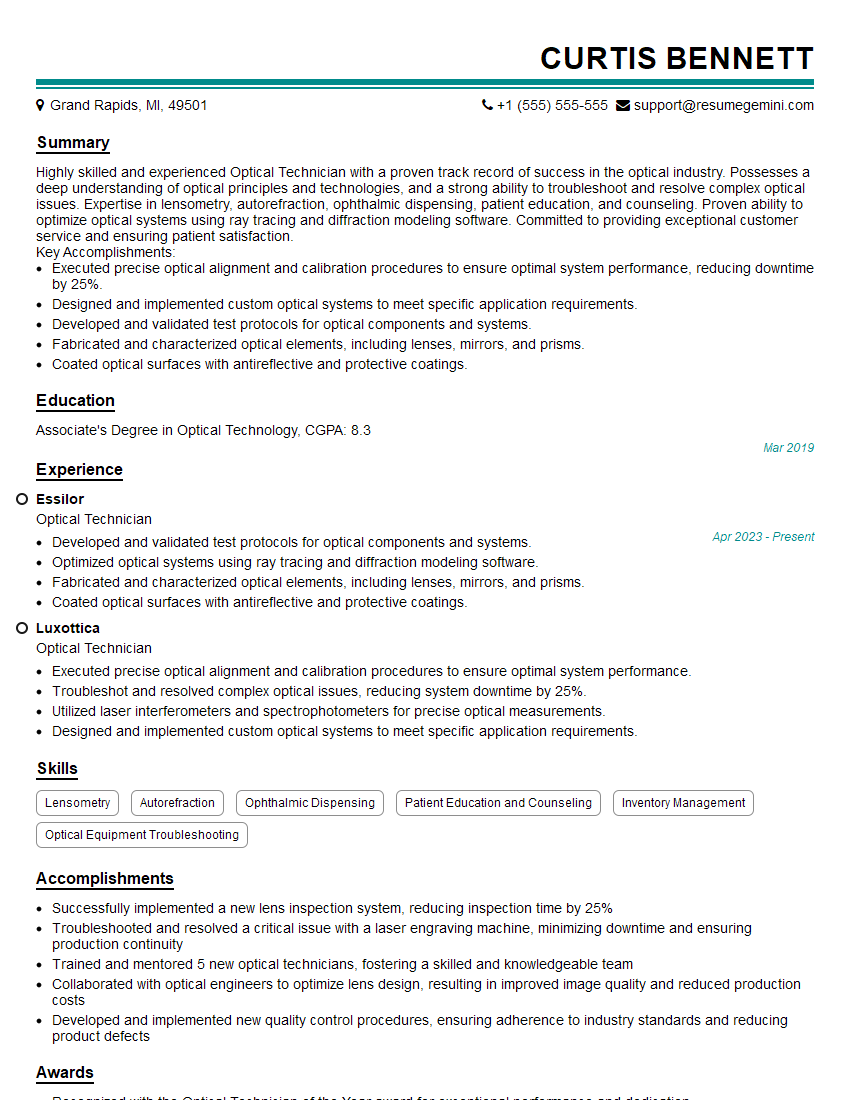
Mastering Optical Fabrication opens doors to exciting career opportunities in a rapidly growing field, offering diverse roles in research, development, and manufacturing. To maximize your job prospects, a well-crafted, ATS-friendly resume is crucial. ResumeGemini is a trusted resource that can help you build a professional resume tailored to highlight your skills and experience in Optical Fabrication. Examples of resumes specifically designed for this field are available to help guide you. Invest time in presenting yourself effectively – your expertise deserves to be recognized!

Explore more articles
Users Rating of Our Blogs
Share Your Experience
We value your feedback! Please rate our content and share your thoughts (optional).
What Readers Say About Our Blog
Very informative content, great job.
good