Preparation is the key to success in any interview. In this post, we’ll explore crucial Power System Management interview questions and equip you with strategies to craft impactful answers. Whether you’re a beginner or a pro, these tips will elevate your preparation.
Questions Asked in Power System Management Interview
Q 1. Explain the difference between symmetrical and unsymmetrical faults in power systems.
Faults in power systems are classified based on their symmetry. Symmetrical faults involve all three phases equally, resulting in a balanced fault current. Unsymmetrical faults, conversely, affect only one or two phases, creating an unbalanced fault current. Imagine a three-legged stool: a symmetrical fault is like breaking all three legs simultaneously, while an unsymmetrical fault is like breaking only one or two.
Symmetrical Faults: These are relatively simpler to analyze because of their balanced nature. A three-phase short circuit is the most common example. Analysis uses symmetrical components (positive, negative, and zero sequence) to simplify calculations.
Unsymmetrical Faults: These are more complex and require more sophisticated analysis techniques. Examples include single-line-to-ground faults, line-to-line faults, and double-line-to-ground faults. The unbalance leads to different current magnitudes and phases in the different phases.
Practical Implications: Understanding the type of fault is crucial for proper relay coordination and protection scheme design. Symmetrical fault analysis provides a simplified initial estimation, but unsymmetrical fault analysis is necessary for accurate protection settings and to prevent cascading failures.
Q 2. Describe the operating principles of a synchronous generator.
A synchronous generator, the workhorse of power systems, operates based on the principle of electromagnetic induction. It’s essentially a rotating machine that converts mechanical energy (from turbines powered by steam, water, or gas) into electrical energy.
Here’s a breakdown:
- Rotor: A rotating magnetic field is created by DC excitation current flowing through field windings on the rotor. This creates the North and South poles.
- Stator: Stationary windings (armature windings) are placed on the stator. As the rotor rotates, the changing magnetic flux cuts across these stator windings, inducing an electromotive force (EMF), thus generating AC current.
- Frequency: The frequency of the generated AC voltage is directly proportional to the rotational speed of the rotor (number of poles x speed / 120). This needs to be synchronized with the grid frequency.
In simpler terms: Imagine a magnet spinning inside a coil of wire. The spinning magnet creates a changing magnetic field around the coil. This changing field induces an electrical current in the coil. The speed of the spinning magnet determines the frequency of the generated electricity.
Practical Application: Synchronous generators are the primary source of electricity in most power systems. Their ability to maintain synchronous operation (constant frequency and voltage) is crucial for the stable operation of the entire grid.
Q 3. What are the different types of protective relays used in power systems?
Protective relays are the ‘nervous system’ of a power system, instantly detecting faults and initiating protective actions. There’s a wide variety of relays, each designed for specific fault types and locations. Some common types include:
- Overcurrent Relays: These detect excessive current flow, indicating a short circuit or overload. They have different characteristics (e.g., instantaneous, time-delayed) to coordinate with circuit breakers.
- Differential Relays: These compare the current entering and leaving a protected zone (e.g., a transformer). Any significant difference indicates an internal fault.
- Distance Relays: These measure the impedance to the fault. They can be very fast and operate within the first few cycles of a fault.
- Ground Fault Relays: Detect ground faults, which are particularly dangerous because they can create a risk of electric shock.
- Busbar Protection: Monitors the busbar for faults. It employs various techniques like differential protection, distance protection, or current and voltage monitoring.
- Generator Protection: Specific relays that protect the generator against overspeed, loss of excitation, stator faults, and other generator related issues.
- Transformer Protection: Relays specifically designed to protect transformers from overcurrent, overheating, internal faults, and other issues.
Practical Application: Properly selected and coordinated relays are essential for isolating faults quickly and preventing damage to equipment and disruptions to power supply. Incorrect settings can lead to unnecessary tripping or failure to clear faults, potentially causing widespread blackouts.
Q 4. Explain the function of a circuit breaker and its role in power system protection.
A circuit breaker is a critical component of power system protection. It acts as a switch that can automatically interrupt the flow of electricity under fault conditions or during planned outages. Think of it as a high-voltage, lightning-fast switch that can handle massive currents.
Function: When a protective relay detects a fault, it sends a signal to the circuit breaker to trip (open). This interrupts the fault current, preventing further damage and ensuring system stability. Circuit breakers can also be manually operated for maintenance or other planned interruptions.
Role in Power System Protection: The circuit breaker is the final line of defense. It isolates the faulty section of the system, preventing the fault from spreading and causing larger-scale problems. The speed at which a circuit breaker operates is crucial in limiting the damage caused by the fault.
Practical Application: Consider a short circuit in a power line. Overcurrent relays detect the excessive current, send a trip signal to the circuit breaker, which then quickly isolates the faulty line, limiting the extent of the outage and preventing potential fires or other hazards.
Q 5. How does a transformer work, and what are its key parameters?
A transformer is a static device that changes the voltage of alternating current (AC) electricity. It’s based on the principle of electromagnetic induction: a changing magnetic field induces a voltage in a nearby coil of wire.
How it works: A transformer consists of two coils (primary and secondary) wound around a common ferromagnetic core. AC current flowing in the primary coil creates a changing magnetic field in the core. This changing field induces an EMF in the secondary coil, resulting in a voltage transformation. The ratio of the number of turns in the primary and secondary coils determines the voltage transformation ratio (Vsecondary/Vprimary = Nsecondary/Nprimary).
Key Parameters:
- Turns Ratio (Ns/Np): Determines the voltage transformation.
- Voltage Rating (Primary and Secondary): Indicates the maximum voltage the transformer can handle on each side.
- Current Rating (Primary and Secondary): Indicates the maximum current the transformer can handle on each side.
- KVA Rating: Indicates the apparent power handling capacity of the transformer.
- Efficiency: Measures the effectiveness of the transformer in converting power from primary to secondary.
- Impedance: Represents the internal resistance and reactance of the transformer.
Practical Application: Transformers are essential for power transmission and distribution. They step-up voltage for efficient long-distance transmission and step-down voltage for safe and usable levels at consumers’ premises.
Q 6. What are the different types of power system stabilizers (PSS) and their functions?
Power System Stabilizers (PSS) are supplementary controllers used to enhance the stability of synchronous generators. They improve the damping of low-frequency oscillations that can occur in power systems. Think of them as shock absorbers for the power grid.
Types of PSS:
- Conventional PSS: Uses a simple lead-lag compensator to provide additional damping. They typically utilize the generator’s speed deviation as the input signal.
- Excitation-Based PSS: They directly modulate the excitation system of the generator to provide additional damping to the oscillations.
- Power System Stabilizers based on Wide-Area Measurement Systems (WAMS): These leverage data from wide-area measurements for improved damping of inter-area oscillations across large power systems.
Functions:
- Enhance Damping: The primary function is to increase the damping of low-frequency oscillations in the power system, thus preventing them from growing uncontrollably.
- Improve Stability Margins: By increasing damping, they increase the system’s stability margins, making it more robust against disturbances.
- Prevent Cascading Failures: Effective damping helps prevent oscillations from escalating and triggering cascading outages.
Practical Application: PSS are crucial for maintaining grid stability, particularly in large interconnected systems. They improve the transient and dynamic stability performance under various operating conditions, mitigating the risk of system-wide blackouts. They are particularly useful when the power system operates close to its stability limits.
Q 7. Explain the concept of power system stability and its different types.
Power system stability refers to the ability of the power system to maintain synchronism between generators and loads after being subjected to disturbances. Imagine a tightrope walker: stability is their ability to stay balanced despite external forces (wind gusts).
Types of Power System Stability:
- Angle Stability (Rotor Angle Stability): This concerns the ability of synchronous generators to remain in synchronism. Disturbances can cause changes in the rotor angles of generators, and if these angles diverge excessively, the generators will lose synchronism, resulting in a blackout.
- Frequency Stability: This relates to the ability of the system to maintain the nominal frequency after a large disturbance. A significant loss of generation or a large increase in load can cause a drop in frequency, potentially leading to widespread instability.
- Voltage Stability: This addresses the ability of the system to maintain voltage levels within acceptable limits after a disturbance. A sudden increase in load or a fault can cause a voltage collapse, leading to equipment damage and outages.
Practical Application: Understanding and ensuring different types of power system stability are essential for secure and reliable operation of electricity grids. System operators use various techniques to improve stability, including appropriate generator dispatch, reactive power control, and the installation of power system stabilizers (PSS) to prevent instability, voltage collapse, and large-scale blackouts.
Q 8. What is load flow analysis, and what are its applications?
Load flow analysis, or power flow analysis, is a crucial process in power system engineering that determines the steady-state operating conditions of an electrical power system network. It calculates the voltage magnitude and phase angle at each bus (node) in the network, as well as the real and reactive power flowing through each transmission line. Think of it like mapping the flow of electricity through a complex network of roads.
Applications:
- Power system planning: Load flow studies help determine the optimal location and size of new power generation units and transmission lines to meet future demand.
- System operation: Real-time load flow analysis is used to monitor the system’s stability and prevent overloads or voltage violations. Power system operators use this information to make decisions about dispatching generation and managing transmission constraints.
- Fault analysis: Load flow results are often used as the initial condition for fault calculations, providing a starting point for assessing the impact of various fault scenarios.
- State estimation: Load flow analysis forms the basis for state estimation, a process of estimating the system’s state based on measured data from various sensors across the network. This enhances situational awareness for system operators.
- Economic dispatch: Load flow analysis is incorporated into economic dispatch algorithms, which determine the most economical way to meet the system’s load demand while considering the generation costs of different power plants.
Example: Imagine a city’s power grid. Load flow analysis helps determine the voltage levels at different neighborhoods and the amount of power flowing through each transmission line. If a new factory is built, this analysis helps predict if the grid needs upgrades to accommodate the increased load.
Q 9. Describe different methods for fault calculation in power systems.
Fault calculation in power systems determines the consequences of various faults (short circuits, ground faults, etc.) on the system’s operation. This is critical for designing protective relay systems and ensuring the safety and stability of the grid. Several methods exist:
- Symmetrical Component Method: This classic method simplifies unbalanced fault analysis by transforming the unbalanced fault currents into symmetrical components (positive, negative, and zero sequence). It’s widely used because it handles various fault types systematically.
Example: Analyzing a line-to-ground fault using the transformation matrices. - Z-bus Method: This method uses the impedance matrix (Z-bus) of the system to directly calculate fault currents. It’s computationally efficient for small systems but can become complex for large networks.
Example: Calculating the fault current at a specific bus using the Z-bus matrix and the fault impedance. - Y-bus Method: This method uses the admittance matrix (Y-bus) of the system and is particularly efficient for large systems. It is often used in conjunction with iterative techniques.
Example: Solving a network's Y-bus matrix for a fault and finding the bus voltages. - Fault Location Algorithms: These advanced techniques use measurements from various points in the system to estimate the location of a fault along a transmission line, enabling faster fault isolation and restoration. These often involve wave propagation analysis or impedance-based methods.
The choice of method depends on the size and complexity of the power system, the type of fault being analyzed, and the required level of accuracy. Many power system simulation software packages incorporate these methods to efficiently perform fault calculations.
Q 10. What are the advantages and disadvantages of different transmission voltage levels?
Transmission voltage levels significantly impact power system design and operation. Higher voltages generally offer advantages, but also come with increased costs and complexities.
- Higher Voltage Levels (e.g., 500 kV, 765 kV):
- Advantages: Reduced transmission losses (I²R losses are inversely proportional to the square of the voltage), increased power transfer capability for a given line size, and smaller conductor cross-sections leading to reduced material costs.
- Disadvantages: Higher insulation requirements, increased cost of equipment (transformers, insulators, etc.), greater safety concerns due to high voltages, and more complex protection systems.
- Lower Voltage Levels (e.g., 115 kV, 230 kV):
- Advantages: Lower equipment costs, simpler protection systems, and reduced safety concerns.
- Disadvantages: Higher transmission losses, lower power transfer capability, and larger conductor cross-sections increasing material costs and right-of-way requirements.
Practical Application: Long-distance power transmission often utilizes very high voltage levels (e.g., 500kV and above) to minimize transmission losses over hundreds of kilometers. However, distribution networks closer to consumers typically use much lower voltages (e.g., 115kV to 13.8kV) due to safety and economic factors.
The choice of voltage level involves a careful trade-off between economic and technical considerations. Cost-benefit analysis is commonly used to determine the optimal voltage level for a specific application.
Q 11. Explain the concept of power system harmonics and their impact.
Power system harmonics are sinusoidal voltages or currents with frequencies that are integer multiples of the fundamental frequency (typically 50Hz or 60Hz). These are caused by non-linear loads, such as rectifiers, inverters, and switching power supplies, which draw non-sinusoidal currents from the power system. Think of it as ripples added to the smooth flow of electricity.
Impact:
- Overheating of equipment: Harmonic currents can cause excessive heating in transformers, motors, and other equipment, leading to premature failure.
- Resonance: Harmonics can interact with the system’s impedance to cause resonance, leading to amplified harmonic currents and voltages. This can result in voltage distortion and potential equipment damage.
- Malfunctioning of protective relays: Harmonic currents can interfere with the operation of protective relays, potentially leading to incorrect tripping or failure to operate during faults.
- Increased losses: Harmonic currents cause increased losses in transmission lines and transformers.
- Interference with communication systems: Harmonics can create interference in communication systems operating near power lines.
Mitigation: Harmonics are mitigated using techniques such as harmonic filters (passive or active), specially designed transformers, and improved power factor correction.
Q 12. How is power quality maintained in a power system?
Maintaining power quality is crucial for reliable and efficient power system operation. It encompasses various aspects, ensuring electricity delivered meets acceptable standards for voltage, frequency, waveform, and other parameters.
Methods:
- Voltage regulation: Using voltage regulators, tap changers on transformers, and reactive power compensation devices to maintain the voltage within acceptable limits.
- Frequency control: Employing automatic generation control (AGC) to regulate the system frequency around its nominal value (50Hz or 60Hz).
- Power factor correction: Installing capacitor banks or other reactive power compensation devices to improve the power factor and reduce harmonic distortion.
- Harmonic filtering: Using passive or active filters to reduce harmonic currents and voltages.
- Surge protection: Implementing surge arresters and other surge protection devices to protect equipment from voltage surges and lightning strikes.
- Uninterruptible power supplies (UPS): Providing backup power to critical loads during outages or voltage dips.
- Fault detection and isolation: Using protective relays and other fault detection devices to quickly isolate faults and prevent widespread outages.
Practical Example: A hospital relies heavily on maintaining high power quality to ensure the continuous and reliable operation of life-support systems. The use of UPS systems and sophisticated power quality monitoring equipment is crucial in such applications.
Q 13. What are the challenges associated with integrating renewable energy sources into the grid?
Integrating renewable energy sources (RES) like solar and wind power presents several challenges for the power system:
- Intermittency and variability: RES generation is inherently intermittent (sunlight and wind are not constant) and variable, making it difficult to predict their output. This impacts system stability and reliability.
- Grid stability issues: The fluctuating nature of RES can lead to voltage fluctuations, frequency deviations, and other stability issues. Special control mechanisms are needed to maintain grid stability.
- Grid infrastructure limitations: Existing grid infrastructure may not be adequately designed to accommodate the decentralized and geographically dispersed nature of many RES projects.
- Integration costs: Integrating RES often requires upgrading transmission lines, substations, and other grid infrastructure, incurring significant costs.
- Power quality issues: Some RES technologies, especially those utilizing inverters, can inject harmonic currents into the grid, degrading power quality.
- Lack of inertia: Unlike traditional synchronous generators, many RES don’t provide inertia to the grid, making the system more vulnerable to frequency fluctuations.
Mitigation Strategies: Solutions include energy storage technologies (batteries, pumped hydro), advanced control systems, smart grid technologies, grid modernization, and demand-side management.
Q 14. Explain the concept of smart grids and their benefits.
Smart grids are modernized electricity networks that utilize digital technologies to enhance efficiency, reliability, and sustainability. Think of it as a more intelligent and responsive power system.
Key features:
- Advanced metering infrastructure (AMI): Smart meters provide real-time data on energy consumption, enabling better demand-side management.
- Two-way communication: Enables communication between utilities and consumers, facilitating dynamic pricing and demand response programs.
- Distributed generation integration: Facilitates the integration of renewable energy sources and distributed generation resources into the grid.
- Improved grid monitoring and control: Real-time monitoring and advanced control algorithms enhance grid stability and reliability.
- Advanced analytics: Data analytics are used to optimize grid operations, predict outages, and improve energy efficiency.
Benefits:
- Increased efficiency: Reduced transmission and distribution losses, optimized energy use.
- Improved reliability: Faster fault detection and isolation, reduced outage times.
- Enhanced sustainability: Increased integration of renewable energy sources, reduced carbon emissions.
- Cost savings: Reduced operational costs for utilities and consumers.
- Improved customer experience: Greater control over energy consumption and access to real-time information.
Q 15. Describe the role of SCADA in power system management.
SCADA, or Supervisory Control and Data Acquisition, is the nervous system of a power system. It’s a centralized system that allows operators to monitor and control geographically dispersed assets like substations, generators, and transmission lines. Think of it as a massive, real-time dashboard displaying the health and status of the entire grid.
SCADA systems collect data from Remote Terminal Units (RTUs) and Programmable Logic Controllers (PLCs) located at various points in the power system. This data – voltage, current, frequency, power flow, and more – is transmitted to a central control room. Operators then use this information to make informed decisions, remotely adjusting equipment settings to maintain stability and reliability. For example, if a line overload is detected, SCADA can automatically shed load or reroute power to prevent a blackout.
Imagine a vast network of interconnected pipes carrying water (electricity). SCADA acts like a sophisticated control center monitoring the water pressure (voltage), flow rate (current), and the overall health of the pipes (transmission lines). Any leaks or blockages are instantly detected and addressed to ensure a continuous supply of water to all consumers.
Career Expert Tips:
- Ace those interviews! Prepare effectively by reviewing the Top 50 Most Common Interview Questions on ResumeGemini.
- Navigate your job search with confidence! Explore a wide range of Career Tips on ResumeGemini. Learn about common challenges and recommendations to overcome them.
- Craft the perfect resume! Master the Art of Resume Writing with ResumeGemini’s guide. Showcase your unique qualifications and achievements effectively.
- Don’t miss out on holiday savings! Build your dream resume with ResumeGemini’s ATS optimized templates.
Q 16. What is the purpose of an Energy Management System (EMS)?
An Energy Management System (EMS) is the brain of the power system, going beyond the monitoring capabilities of SCADA. It uses advanced algorithms and sophisticated software to optimize the entire power grid’s operation, ensuring efficient, reliable, and economical power delivery.
The EMS performs several crucial functions, including state estimation (determining the real-time conditions of the grid), economic dispatch (optimizing generation to minimize costs while meeting demand), and security analysis (assessing the grid’s vulnerability to contingencies like line outages).
For example, an EMS can predict the impact of a sudden increase in demand and automatically adjust generation output from various power plants to meet the new demand, all while minimizing fuel consumption. It also helps prevent cascading failures by identifying weak points in the grid and proactively taking corrective actions.
In essence, while SCADA provides the ‘what’ (the current state of the system), the EMS provides the ‘why’ (the reasons behind the observed state) and the ‘how’ (the optimal strategies to maintain stability and efficiency).
Q 17. Explain different methods for power system optimization.
Power system optimization aims to enhance the efficiency and reliability of electricity generation, transmission, and distribution. Several methods are employed:
- Economic Dispatch: This minimizes the overall cost of generation by allocating power production among different power plants based on their fuel costs and operational constraints. It’s like deciding which factories to use to produce a certain number of goods at the lowest possible cost.
- Optimal Power Flow (OPF): OPF is a more comprehensive approach that considers not only the cost of generation but also network constraints (line limits, voltage limits) to find the optimal operating point for the entire system. It ensures that power flows through the grid safely and efficiently.
- Unit Commitment: This involves determining which generating units to start up and shut down over a given period to meet forecasted demand while minimizing costs and emissions. This is a long-term planning problem, compared to economic dispatch, which deals with short-term decisions.
- State Estimation: Accurate state estimation is crucial for the success of other optimization methods. It involves determining the current state of the power system based on measurements from various points in the network.
These methods often involve complex mathematical models and optimization algorithms, and their implementation necessitates advanced software tools like the EMS.
Q 18. What are the key performance indicators (KPIs) for a power system?
Key Performance Indicators (KPIs) for a power system are crucial for assessing its performance and identifying areas for improvement. They can be broadly categorized as:
- Reliability KPIs: These measure the frequency and duration of outages, SAIDI (System Average Interruption Duration Index), SAIFI (System Average Interruption Frequency Index), and CAIDI (Customer Average Interruption Duration Index). Lower values indicate better reliability.
- Efficiency KPIs: These track energy losses during transmission and distribution, plant efficiency (Megawatt-hours produced per unit of fuel), and overall system efficiency.
- Economic KPIs: These focus on the cost of electricity generation, transmission, and distribution, as well as the return on investment for grid modernization projects.
- Security KPIs: These assess the system’s ability to withstand disturbances and contingencies, such as the N-1 criterion (ability to operate safely after a single component failure).
- Environmental KPIs: These measure greenhouse gas emissions, water consumption, and other environmental impacts of power generation.
Regular monitoring and analysis of these KPIs allow power system operators to identify trends, pinpoint weaknesses, and implement necessary improvements.
Q 19. How does power system deregulation affect grid operation?
Power system deregulation, which transitioned from vertically integrated monopolies to competitive markets, significantly impacted grid operation. It introduced independent power producers (IPPs) and energy traders, creating a more complex and dynamic environment.
The key changes include:
- Increased competition: Deregulation fostered competition among generators, leading to potentially lower electricity prices but also increasing the need for sophisticated market mechanisms to manage supply and demand.
- Independent System Operators (ISOs) or Regional Transmission Organizations (RTOs): These independent entities were established to manage the transmission grid and ensure fair access for all generators and consumers, maintaining grid stability and security.
- Market-based dispatch: Economic dispatch shifted from cost-minimization in vertically integrated systems to market-based principles, where generators bid into energy markets, and the ISO selects the optimal generation mix based on prices and grid constraints.
- Increased complexity: The interaction between numerous market participants requires more advanced tools and methods for grid management, including sophisticated EMS and market simulation models.
Deregulation often leads to improved efficiency and lower prices but also necessitates more sophisticated tools and protocols to maintain the reliability and security of the power grid.
Q 20. Explain the concept of reactive power compensation.
Reactive power compensation involves adjusting the reactive power in a power system to improve voltage profiles, reduce transmission losses, and enhance system stability. Reactive power, unlike active power (which does actual work), is associated with the magnetic fields in inductive components like transformers and transmission lines.
Excessive reactive power can lead to low voltage levels, increased transmission losses, and even instability. Compensation techniques aim to balance reactive power generation and consumption.
Methods include:
- Capacitor banks: These are passive devices that generate reactive power, improving voltage levels and reducing losses. They are like adding extra water pressure to a pipeline.
- Synchronous condensers: These are rotating machines that can generate or absorb reactive power as needed. They provide more flexible reactive power control compared to capacitor banks.
- Static VAR compensators (SVCs): These are thyristor-controlled devices that can rapidly adjust reactive power generation based on grid conditions. They are highly sophisticated and offer fast response times.
- STATCOM (Static Synchronous Compensator): Similar to SVCs, these are power electronic devices capable of regulating both voltage and reactive power, allowing for finer control and improved dynamic response.
By strategically deploying these devices, power system operators can optimize voltage profiles, minimize losses, and enhance the system’s overall performance and stability.
Q 21. Describe different methods for improving power system reliability.
Improving power system reliability involves various strategies targeting different aspects of the system:
- Redundancy: Incorporating backup systems and parallel paths for power flow reduces the impact of component failures. This is akin to having multiple routes to reach a destination.
- Preventive maintenance: Regularly inspecting and maintaining equipment minimizes the risk of unexpected failures. This is like routinely servicing a car to prevent breakdowns.
- Protective relaying: Advanced protection systems quickly isolate faulty equipment, limiting the extent of outages. This acts as a safety mechanism to prevent wider damage.
- Smart grids: Utilizing advanced technologies like sensors, communication networks, and automated control systems allows for real-time monitoring, faster fault detection, and self-healing capabilities.
- Demand-side management (DSM): Implementing programs to encourage consumers to shift their energy usage patterns can reduce peak demand, improving grid stability and reducing the risk of outages. This is about managing consumption to avoid over-burdening the system.
- Distributed generation (DG): Integrating smaller, decentralized generation sources such as rooftop solar panels and wind turbines enhances the resilience of the power system by reducing dependence on large, centralized power plants.
A comprehensive approach combining these strategies is essential to ensure a reliable and robust power system that meets the needs of consumers.
Q 22. What are the safety considerations in power system maintenance?
Safety is paramount in power system maintenance. Working with high voltages and potentially lethal currents demands rigorous adherence to safety protocols. Think of it like this: we’re dealing with a powerful, invisible force that can be incredibly dangerous if not treated with the utmost respect.
- Lockout/Tagout Procedures (LOTO): This is the cornerstone of safety. Before any work begins, all power sources to the equipment must be isolated, locked out, and tagged to prevent accidental energization. This involves a detailed process, often with multiple team members verifying each step.
- Personal Protective Equipment (PPE): Appropriate PPE is crucial, including insulated gloves, safety glasses, arc flash suits (for higher voltage work), and safety footwear. The type and level of PPE will depend on the voltage and nature of the task.
- Grounding and Bonding: This ensures that any stray voltages are safely diverted to the earth, preventing electrical shocks. Proper grounding procedures are vital before any work on energized equipment begins.
- Permit-to-Work Systems: A formal system outlining the tasks, safety precautions, and authorizations required for potentially hazardous work. This ensures everyone understands the risks and the required steps to mitigate them.
- Training and Competency: All personnel involved in maintenance must receive thorough training and demonstrate competency in safe work practices. Regular refresher courses and safety audits are crucial.
- Emergency Response Plans: Clear procedures for handling emergencies, including electrical shocks, fires, or equipment failures, are essential. Regular drills and simulations help prepare the team for real-world scenarios.
A failure to adhere to these safety considerations can lead to serious injury or even fatality. In my experience, a thorough safety briefing and meticulous adherence to procedures are the best ways to ensure a safe working environment.
Q 23. Explain the different types of power system studies (e.g., short-circuit, load flow).
Power system studies are essential for planning, operating, and maintaining electrical grids. They use mathematical models to simulate different operating conditions and predict system behavior. Think of them as virtual stress tests for the power system.
- Load Flow Studies: These studies determine the steady-state voltage and power flow throughout the system under normal operating conditions. They help optimize power generation and distribution, ensuring sufficient capacity and minimizing losses. For example, we use load flow studies to identify potential overloading of lines and transformers.
- Short-Circuit Studies: These determine the magnitude and duration of fault currents during short circuits (faults that cause a low-impedance path). This information is crucial for designing protective devices like circuit breakers and relays, ensuring they can interrupt fault currents effectively and quickly, protecting equipment and personnel.
- Transient Stability Studies: These examine the system’s response to large disturbances, such as sudden loss of a generator or transmission line. This helps assess the system’s ability to maintain synchronism and avoid widespread blackouts. We use this to understand how the system will react to major incidents and plan for appropriate control actions.
- Harmonic Studies: These analyze the presence of non-sinusoidal current and voltage waveforms (harmonics) that can be generated by non-linear loads like rectifiers and power electronics. Understanding harmonics is vital for preventing equipment damage and interference with communication systems.
Each study type provides valuable insights, and often they’re used in combination to gain a holistic understanding of the power system’s performance.
Q 24. Discuss the impact of distributed generation on power system operation.
Distributed generation (DG), such as rooftop solar panels and small-scale wind turbines, is significantly changing power system operation. While offering many benefits, it also introduces new challenges.
- Increased System Flexibility: DG can provide power closer to the load, reducing transmission losses and improving voltage profiles. Imagine a microgrid during a blackout – DG can provide localized power, reducing the impact of the outage.
- Improved Reliability: DG can serve as backup power during outages, improving system resilience. Think of it as distributed insurance against grid disruptions.
- Voltage Regulation Challenges: The intermittent nature of renewable DG sources (like solar and wind) can cause voltage fluctuations. Advanced control systems are needed to maintain stable voltage levels.
- Protection Coordination Issues: DG can complicate protective relay coordination, as faults may be fed from multiple sources. This requires advanced protection schemes and careful coordination.
- Islanding Concerns: DG can inadvertently create islands in the grid during faults. This can be dangerous for both line workers and equipment. Sophisticated islanding detection and mitigation systems are needed.
Successfully integrating DG requires a thoughtful approach that considers both its benefits and challenges. This includes implementing smart grids, advanced control systems, and robust protection schemes. I’ve personally been involved in projects that used advanced power flow and stability simulations to evaluate the impact of various DG integration scenarios.
Q 25. How do you address voltage sags and swells in a power system?
Voltage sags (short-duration voltage dips) and swells (short-duration voltage increases) are undesirable events that can disrupt sensitive equipment. Addressing them requires a multi-pronged approach.
- Improved Power System Planning: Careful planning and design can help minimize sags and swells by ensuring adequate system capacity and reducing impedance.
- Fault Mitigation Techniques: Rapid fault clearing through advanced protection systems is key to reducing the duration and severity of voltage disturbances.
- Power Quality Equipment: Voltage sag compensators (VSCs), dynamic voltage restorers (DVRs), and uninterruptible power supplies (UPS) can mitigate the impact of sags and swells on sensitive loads. These act as buffers, maintaining a relatively stable voltage supply despite grid disturbances.
- Load Management Strategies: Strategies like load shedding (temporarily disconnecting less critical loads) can reduce the impact of major disturbances on the system.
- Monitoring and Analysis: Monitoring voltage levels and analyzing the causes of sags and swells are essential for proactive mitigation. This involves employing advanced monitoring systems that provide real-time data and detailed fault analysis.
The best solution depends on the specific cause and severity of the voltage disturbances. In practice, a combination of improved system planning, proactive maintenance, and power quality equipment is typically implemented.
Q 26. Explain the role of FACTS devices in power system control.
Flexible AC Transmission Systems (FACTS) devices are power electronic-based controllers that enhance the controllability and stability of power systems. Think of them as smart valves and switches for the electric grid, enabling more efficient and reliable power transmission.
- Thyristor-Controlled Series Capacitors (TCSCs): These devices can control the impedance of transmission lines, improving power flow and stability. They effectively fine-tune the grid’s response to fluctuating demands.
- Static Synchronous Compensators (STATCOMs): These devices can provide reactive power compensation, improving voltage regulation and stability. They help maintain voltage within acceptable limits even during disturbances.
- Unified Power Flow Controllers (UPFCs): These versatile devices can control both active and reactive power flow, offering enhanced control capabilities compared to TCSCs and STATCOMs. They allow for more precise management of power flows and voltage levels.
FACTS devices significantly improve power system control by enabling faster and more precise responses to changes in load and generation. They play a crucial role in enhancing system stability, improving power transfer capability, and mitigating voltage fluctuations. I have firsthand experience in integrating STATCOMs into a large power grid project to enhance voltage control in a region with high penetration of renewable energy sources.
Q 27. What are the environmental considerations in power system planning?
Environmental considerations are increasingly critical in power system planning. We must balance the need for reliable electricity with the need to minimize environmental impact.
- Greenhouse Gas Emissions: The primary concern is reducing greenhouse gas emissions from power generation. This involves promoting renewable energy sources like solar, wind, and hydro and phasing out fossil fuel-based generation.
- Air and Water Pollution: Minimizing air and water pollution from power plants is crucial. This includes stringent emission controls and responsible waste management.
- Land Use Impacts: Power plants and transmission lines require land, impacting ecosystems and communities. Careful siting and mitigation strategies are necessary to minimize these impacts.
- Biodiversity Considerations: Power generation and transmission can affect biodiversity. Environmental impact assessments are crucial to identify and mitigate potential harm to wildlife and ecosystems.
- Noise Pollution: Minimizing noise pollution from power plants and transmission lines is also a key concern, especially for communities located nearby.
Sustainable power system planning involves integrating environmental considerations throughout the entire lifecycle of power projects, from initial planning and design to operation and decommissioning. This often involves integrating advanced tools and techniques for environmental impact assessment and mitigation. I was involved in a recent project where we leveraged GIS mapping and environmental modeling software to optimize the siting of a new wind farm, minimizing impact on bird migration routes.
Q 28. Describe your experience with power system simulation software (e.g., PSS/E, PowerWorld).
I have extensive experience with several power system simulation software packages, including PSS/E and PowerWorld Simulator. These tools are essential for analyzing and optimizing power systems.
- PSS/E: I’ve used PSS/E extensively for various studies, including load flow, short-circuit, stability, and dynamic simulations. Its robust capabilities make it suitable for complex system analyses. For example, I used PSS/E to analyze the impact of a major transmission line upgrade on the system’s stability.
- PowerWorld Simulator: I find PowerWorld Simulator’s user-friendly interface and efficient algorithms ideal for quick analyses and visualizing results. I’ve used it for various projects, including planning studies for distribution systems and exploring the impact of distributed generation on voltage profiles. A recent project involved using PowerWorld to optimize the placement of capacitors in a distribution network to improve voltage regulation.
My proficiency in these software packages allows me to perform accurate and efficient analyses, contributing to better power system design, operation, and control. I’m comfortable with both the theoretical underpinnings and practical application of these tools.
Key Topics to Learn for Power System Management Interview
- Power System Operation and Control: Understanding real-time monitoring, load forecasting, economic dispatch, and voltage/frequency control. Practical application: Analyzing system stability during peak demand periods.
- Power System Protection and Relaying: Knowledge of protective relays, fault detection, and system isolation techniques. Practical application: Designing a protection scheme for a new transmission line.
- Power System Stability and Control: Understanding transient stability, small-signal stability, and the role of FACTS devices. Practical application: Analyzing the impact of renewable energy integration on system stability.
- Power System Planning and Design: Knowledge of power flow studies, optimal power flow, and expansion planning. Practical application: Designing a new substation to meet future load growth.
- Power System Analysis Techniques: Proficiency in using simulation software (e.g., PSS/E, PowerWorld Simulator) and understanding various analytical methods. Practical application: Modeling and simulating different fault scenarios.
- Renewable Energy Integration: Understanding the challenges and opportunities associated with integrating renewable energy sources (solar, wind) into the power grid. Practical application: Evaluating the impact of intermittent renewable generation on grid reliability.
- Smart Grid Technologies: Familiarity with advanced metering infrastructure (AMI), distributed generation control, and demand-side management. Practical application: Designing a smart grid solution for improved efficiency and reliability.
Next Steps
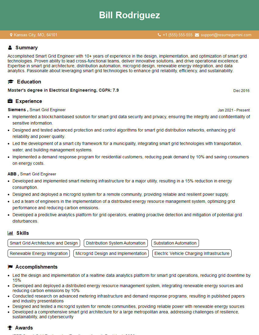
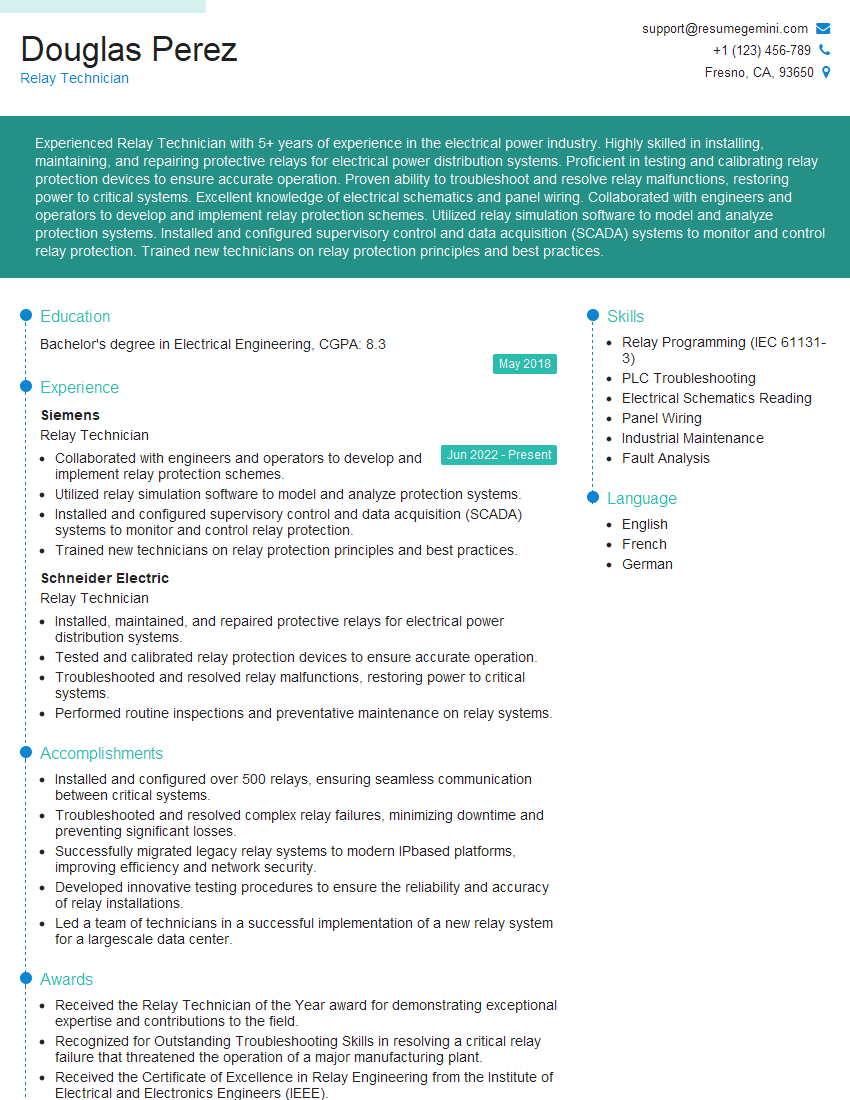
Mastering Power System Management opens doors to exciting and impactful careers in the energy sector, offering opportunities for innovation and contributing to a sustainable energy future. To maximize your job prospects, it’s crucial to present your skills effectively. Creating an ATS-friendly resume is key to getting your application noticed by recruiters. We highly recommend using ResumeGemini, a trusted resource for building professional and impactful resumes. ResumeGemini provides examples of resumes tailored to Power System Management, allowing you to craft a document that showcases your expertise and experience in the best possible light. Take the next step towards your dream career today!
Explore more articles
Users Rating of Our Blogs
Share Your Experience
We value your feedback! Please rate our content and share your thoughts (optional).
What Readers Say About Our Blog
Very informative content, great job.
good