Cracking a skill-specific interview, like one for Mechanical Design and Engineering, requires understanding the nuances of the role. In this blog, we present the questions you’re most likely to encounter, along with insights into how to answer them effectively. Let’s ensure you’re ready to make a strong impression.
Questions Asked in Mechanical Design and Engineering Interview
Q 1. Explain the design process you typically follow.
My design process adheres to a structured, iterative approach, generally following these key phases:
- Problem Definition and Requirements Gathering: This crucial first step involves a thorough understanding of the project’s objectives, constraints (budget, timeline, materials), and performance requirements. We might use tools like Pugh matrices to compare different design concepts.
- Conceptual Design: Here, I brainstorm and sketch multiple potential solutions, considering different approaches and trade-offs. This often involves freehand sketching and quick CAD mockups to explore various ideas visually.
- Preliminary Design: From the conceptual stage, we select the most promising design and refine it. This involves detailed CAD modeling, preliminary calculations (e.g., stress analysis using simplified methods), and material selection based on performance and cost.
- Detailed Design: This is the most rigorous phase. It focuses on creating precise CAD models, generating detailed drawings, specifying tolerances (using GD&T), and ensuring manufacturability. Finite Element Analysis (FEA) is often performed at this stage to validate the design’s strength and durability.
- Prototyping and Testing: Building and testing prototypes allows for validating the design’s functionality, performance, and manufacturability. We might create multiple prototypes, each addressing specific aspects of the design. Data from testing informs subsequent design iterations.
- Production and Deployment: Once the design is finalized and tested, the next step involves overseeing the manufacturing process and ensuring the product meets all specifications. This phase requires close collaboration with manufacturing engineers.
- Post-launch Evaluation: After the product is launched, gathering feedback and analyzing real-world performance is crucial for continuous improvement. This informs future iterations and new design projects.
For example, in designing a new bicycle frame, we might start by analyzing rider needs (comfort, speed, weight), then explore different frame materials (aluminum, carbon fiber, steel), and finally, test prototypes for stiffness and durability before mass production.
Q 2. Describe your experience with CAD software (e.g., SolidWorks, AutoCAD).
I have extensive experience with various CAD software packages, including SolidWorks, AutoCAD, and Creo Parametric. SolidWorks is my preferred choice for its powerful 3D modeling capabilities, simulation tools (FEA, CFD), and ease of use. I’m proficient in creating complex 3D models, generating detailed 2D drawings, and managing large assemblies. My experience extends to using AutoCAD for 2D drafting and detailed drawings, particularly for projects requiring precise geometric definition. I have utilized Creo Parametric primarily for its robust capabilities in handling large, complex assemblies and its direct integration with manufacturing processes.
For instance, in a recent project designing a robotic arm, I leveraged SolidWorks’ advanced simulation tools to optimize the arm’s structural integrity and movement precision, ensuring it could withstand the required loads and operate within specified tolerances.
Q 3. How do you handle design changes during a project?
Design changes are an inevitable part of any engineering project. My approach involves a structured process to manage these changes effectively:
- Impact Assessment: First, I evaluate the impact of the change request on the overall design, budget, and schedule. This often involves meetings with stakeholders to understand the rationale behind the change.
- Design Modification: Using the CAD software, I make the necessary changes to the design, ensuring that they are integrated seamlessly and do not compromise the integrity of the overall system. I meticulously document all modifications.
- Verification and Validation: After implementing the change, I rigorously verify and validate the design using analysis tools (FEA, tolerance analysis) to ensure that it still meets all performance and safety requirements. Testing may also be required.
- Documentation Update: All changes, including their rationale and impact, are meticulously documented and updated in the design files, drawings, and other relevant documents.
- Communication: Maintaining clear and proactive communication with the project team and stakeholders throughout the process is crucial to ensure everyone is informed of the changes and their potential implications.
For example, if a client requests a change in the material of a component mid-project, I’d assess the implications on strength, weight, cost and manufacturability. I’d then update the CAD model, perform new FEA, and communicate the revised timeline and cost to the client before proceeding.
Q 4. What are your preferred methods for stress analysis and FEA?
My preferred methods for stress analysis and FEA involve using industry-standard software packages such as ANSYS and SolidWorks Simulation. I’m proficient in setting up models, defining material properties, applying boundary conditions and loads, and interpreting the results.
For stress analysis beyond FEA, I utilize hand calculations and simplified methods (like beam theory, shear stress calculations) for preliminary assessments and verification. These quick analyses can identify potential issues early in the design phase, saving time and resources.
In choosing the appropriate method, I consider factors such as the complexity of the geometry, the loading conditions, the required accuracy, and the available time and resources. For example, a simple beam might be adequately analyzed using beam theory, while a complex component might require a full-scale FEA.
Q 5. Explain your understanding of tolerance analysis and GD&T.
Tolerance analysis and Geometric Dimensioning and Tolerancing (GD&T) are critical for ensuring the proper functioning of mechanical assemblies. Tolerance analysis involves determining the acceptable variations in component dimensions and their impact on the overall assembly. GD&T is a standardized system for defining and controlling these variations on engineering drawings.
I am skilled in using GD&T symbols to specify tolerances, including size, form, orientation, location, and runout. I use tolerance analysis software and statistical methods to assess the impact of component tolerances on assembly functionality, and also employ Monte Carlo simulations for probabilistic tolerance analysis in complex assemblies. This helps in identifying potential interference or clearance issues early in the design process.
For example, when designing a tight-fitting assembly, I would use GD&T to define the positional tolerance of mating parts, ensuring the assembly functions correctly despite manufacturing variations. The tolerance analysis would help determine the probability of assembly failure due to accumulated tolerances.
Q 6. How do you ensure designs meet safety standards and regulations?
Ensuring designs meet safety standards and regulations is paramount. My approach involves:
- Identifying Applicable Standards: First, I thoroughly research and identify all relevant safety standards and regulations applicable to the project. This might include industry-specific standards (e.g., ISO, ASME), national regulations, and company-specific safety guidelines.
- Design for Safety: Throughout the design process, safety considerations are integrated into every stage. This includes selecting appropriate materials, designing for robust failure modes, incorporating safety features, and using appropriate safety factors in calculations.
- Analysis and Simulation: Using FEA and other simulation tools, I conduct thorough analysis to ensure the design can withstand expected loads and stresses while maintaining a sufficient safety margin. This may involve simulating failure scenarios to identify potential risks.
- Testing and Verification: Rigorous testing is crucial, both during prototyping and final product validation. This might involve destructive testing to determine failure points, fatigue testing to assess long-term durability, and functional testing to ensure safe operation.
- Documentation and Compliance: All safety-related aspects of the design are meticulously documented, including test results, safety analysis reports, and compliance certifications. This ensures traceability and accountability.
For instance, when designing pressure vessels, we rigorously adhere to ASME Boiler and Pressure Vessel Code to ensure the vessel can safely contain the pressure while preventing catastrophic failure.
Q 7. Describe your experience with material selection for mechanical components.
Material selection is a critical aspect of mechanical design, impacting performance, cost, and manufacturability. My approach is based on a thorough understanding of material properties and their suitability for the intended application. This includes considering factors like:
- Strength and Stiffness: Yield strength, tensile strength, and Young’s modulus determine the material’s ability to withstand loads and deformations.
- Fatigue Resistance: Crucial for components subjected to cyclic loading, this determines the material’s ability to withstand repeated stress cycles without failure.
- Corrosion Resistance: Essential for components exposed to corrosive environments, this factor ensures the material’s long-term durability and prevents degradation.
- Cost and Availability: Balancing performance requirements with economic considerations is essential for selecting the most cost-effective material.
- Manufacturability: Considering how the material will be processed (machining, casting, forging) is important for ease of manufacturing and overall cost.
- Temperature Considerations: High or low-temperature operation may require specific materials with appropriate thermal properties.
For example, choosing between aluminum and steel for a car chassis involves considering weight, strength, cost, and manufacturability. Aluminum alloys offer a good strength-to-weight ratio but might be more expensive than steel. The final decision depends on prioritizing performance and cost targets. I frequently use material selection software and databases to streamline this process and compare options objectively.
Q 8. How do you manage and prioritize multiple engineering projects?
Managing multiple engineering projects effectively requires a structured approach. I typically employ a prioritization matrix, considering factors like project deadlines, strategic importance, resource availability, and potential impact. This allows me to visualize all projects and their interdependencies. For example, I might use a weighted scoring system, assigning weights to criteria like urgency and complexity. Projects with higher scores receive immediate attention. I also utilize project management software to track progress, deadlines, and resource allocation, ensuring transparency and accountability across the team. Beyond prioritization, effective time management is crucial. I break down large projects into smaller, manageable tasks, setting realistic deadlines for each. Regular progress reviews and stakeholder communication are vital for keeping projects on track and adapting to changing priorities.
Q 9. Explain your understanding of manufacturing processes.
My understanding of manufacturing processes encompasses a broad range of techniques, from traditional methods like machining and casting to advanced techniques like additive manufacturing (3D printing) and injection molding. I’m familiar with the strengths and limitations of each process, considering factors like material properties, production volume, cost-effectiveness, and precision requirements when selecting the most appropriate method for a given design. For example, for high-volume production of plastic parts, injection molding is highly efficient. Conversely, for prototypes or small-batch production of complex geometries, 3D printing offers flexibility. I also consider factors like surface finish, tolerances, and assembly processes during the selection process. A deep understanding of these processes is critical for designing parts that are both functional and manufacturable, minimizing costs and ensuring optimal product quality.
Q 10. Describe your experience with testing and validation of mechanical designs.
Testing and validation are integral parts of my design process. My experience spans various testing methodologies, including static and dynamic load testing, fatigue analysis, thermal cycling, and vibration testing. I utilize both physical prototypes and Finite Element Analysis (FEA) simulations to validate designs. For instance, in a recent project involving a robotic arm, I used FEA to simulate stress and strain under various load conditions, identifying potential weak points before physical prototyping. This allowed for iterative design improvements and cost savings. Following simulation, physical prototypes undergo rigorous testing to verify the FEA results and assess performance under real-world conditions. Comprehensive documentation of all testing procedures and results is crucial for demonstrating compliance with safety standards and regulatory requirements.
Q 11. How do you handle design conflicts or disagreements with team members?
Design conflicts are inevitable in collaborative projects. My approach centers on open communication and collaborative problem-solving. I believe in fostering a respectful environment where team members feel comfortable expressing their opinions and concerns. When disagreements arise, I facilitate discussions, encouraging everyone to present their perspectives and rationale. I focus on understanding the underlying technical issues and exploring potential compromises or alternative solutions. Data-driven arguments, supported by analysis and simulation results, often help resolve technical disputes. In cases where a consensus cannot be reached, I work with team leadership to mediate and make informed decisions based on the project’s overall objectives and constraints. The goal is always to find the optimal solution, considering both technical feasibility and practical implications.
Q 12. How do you stay up-to-date with the latest advancements in mechanical engineering?
Staying current in mechanical engineering requires a multi-pronged approach. I regularly read industry publications, such as journals and trade magazines, to stay abreast of the latest research and technological advancements. I actively participate in professional organizations and conferences, networking with colleagues and learning from industry experts. Online courses and webinars provide opportunities for focused learning on specific topics. Furthermore, I leverage online resources like research databases and engineering forums to access technical information and engage in discussions with other professionals. By continuously learning and adapting, I ensure my skills remain relevant and that I can leverage the newest technologies and techniques in my work.
Q 13. Describe a challenging design problem you faced and how you overcame it.
One particularly challenging project involved designing a high-precision robotic gripper for handling delicate microelectronics components. The primary challenge was achieving the necessary level of precision and repeatability while maintaining a robust and reliable design. Initial designs struggled with excessive vibrations and inconsistent gripping force. To overcome this, I implemented a multi-stage approach: First, I conducted a thorough analysis of the required gripping forces and tolerances, utilizing FEA to optimize the gripper’s geometry and material selection. Second, I incorporated vibration damping mechanisms into the design. Finally, I implemented a closed-loop control system to monitor and adjust gripping force in real-time, ensuring consistent and reliable performance. This iterative process, combining simulation, prototyping, and testing, led to a successful solution that met all performance requirements.
Q 14. Explain your experience with design for manufacturability (DFM).
Design for Manufacturability (DFM) is a crucial aspect of my design process. It involves considering the manufacturing capabilities and limitations early in the design phase, aiming to create products that are both functional and cost-effective to produce. This includes selecting appropriate materials, considering tolerances and surface finishes achievable by the chosen manufacturing process, and ensuring the design is easy to assemble. For example, I might avoid designs that require complex machining operations or intricate assembly steps, opting for simpler geometries that are easier to manufacture and less prone to errors. Collaboration with manufacturing engineers is crucial in this process. By involving them early on, I can gain valuable insights into the feasibility and cost-effectiveness of different design options, leading to a more manufacturable and ultimately successful product.
Q 15. How do you utilize different types of engineering drawings?
Engineering drawings are the language of mechanical design, crucial for communicating design intent and manufacturing specifications. I utilize several types, each serving a distinct purpose:
Sketching: Initial brainstorming and conceptualization often involves freehand sketches to quickly explore design ideas. For example, I might sketch different arrangements of components to optimize space or functionality before moving to more formal drawings.
Detailed Drawings: These provide precise geometric information, dimensions, tolerances, and material specifications, essential for manufacturing. Think of the blueprint for a part, specifying every hole, curve, and surface finish. I use CAD software to create these, ensuring accuracy and clarity. For instance, a detailed drawing of a gear would include its module, pressure angle, number of teeth, and material.
Assembly Drawings: These show how individual components fit together to form a complete assembly. Exploded views, showing parts separated but in their correct relative positions, are especially helpful for understanding the assembly process. This is invaluable for maintenance and repair, as well as for assembly instructions. I use these extensively to check for interference or clearance issues before manufacturing.
Section Views: These reveal the internal structure of a component by showing a ‘slice’ through it. This allows for visualizing hidden features that aren’t visible on an external view. For example, a section view of a pipe fitting reveals the internal flow path and connections.
Working Drawings: These encompass all necessary information for manufacturing, including dimensions, tolerances, material specifications, surface finishes, and any special instructions. They are essentially the comprehensive documentation for a part or assembly.
Career Expert Tips:
- Ace those interviews! Prepare effectively by reviewing the Top 50 Most Common Interview Questions on ResumeGemini.
- Navigate your job search with confidence! Explore a wide range of Career Tips on ResumeGemini. Learn about common challenges and recommendations to overcome them.
- Craft the perfect resume! Master the Art of Resume Writing with ResumeGemini’s guide. Showcase your unique qualifications and achievements effectively.
- Don’t miss out on holiday savings! Build your dream resume with ResumeGemini’s ATS optimized templates.
Q 16. What is your understanding of kinematics and dynamics?
Kinematics and dynamics are fundamental to mechanical design. Kinematics deals with the geometry of motion – the position, velocity, and acceleration of bodies without considering the forces causing the motion. Think of it as describing *how* things move. Dynamics, on the other hand, considers the forces and moments that cause the motion. It describes *why* things move the way they do.
In practice, I use kinematics to design mechanisms – the arrangement of parts to achieve a specific motion. For example, designing a robotic arm involves kinematic analysis to determine the joint angles required to position the end-effector at a desired location. Dynamics is crucial for analyzing the forces and stresses on components under motion, such as vibrations in a car engine, ensuring the design can withstand these forces without failure. I often use simulation software to model these systems and predict their behavior before physical prototyping.
Q 17. Explain your experience with 3D printing or additive manufacturing.
I have extensive experience with 3D printing, or additive manufacturing. I’ve used it for rapid prototyping, creating functional parts, and producing small-batch manufacturing runs. I’m proficient in several processes, including:
Fused Deposition Modeling (FDM): Used for creating prototypes from thermoplastic materials. I’ve used this to quickly iterate on design changes, making adjustments based on the physical model. For instance, I used FDM to create a housing for a small electronic device, making iterative changes to the design to optimize for weight and strength.
Stereolithography (SLA): Used for high-resolution prototypes and parts with fine details. This is ideal for applications where surface finish and accuracy are critical. For example, I used SLA to create a master mold for a custom injection-molded plastic part.
Selective Laser Sintering (SLS): Used for creating strong and durable parts from various materials, including nylon and metal powders. This technique is ideal for functional prototypes that must withstand significant loads. I’ve used SLS for creating strong, lightweight components for a small drone.
My experience extends beyond simply operating the machines. I understand the importance of material selection, support structures, post-processing, and the limitations of each process. This knowledge allows me to optimize designs for additive manufacturing, leveraging its strengths while mitigating its weaknesses.
Q 18. Describe your understanding of thermodynamics and heat transfer.
Thermodynamics and heat transfer are essential for designing efficient and reliable systems. Thermodynamics deals with the relationships between heat, work, and energy. Heat transfer focuses on the mechanisms by which heat energy is transferred – conduction, convection, and radiation.
In my work, I apply these principles to design systems that effectively manage heat, preventing overheating and ensuring optimal performance. For example, designing an efficient cooling system for an electronic device involves understanding heat generation, heat transfer paths, and choosing appropriate materials and cooling techniques. I also use computational fluid dynamics (CFD) software to simulate heat transfer and optimize thermal management strategies. Understanding thermodynamics also helps in analyzing the efficiency of engines and power systems, allowing for the design of more fuel-efficient and environmentally friendly technologies.
Q 19. Explain your experience with fluid mechanics and hydraulics.
My experience with fluid mechanics and hydraulics includes designing and analyzing systems involving the flow of liquids and gases. I’ve worked on projects involving:
Pipe networks: Calculating pressure drops, selecting appropriate pipe sizes, and designing efficient fluid transport systems. For instance, I designed a piping system for a chemical plant, ensuring adequate flow rates and minimizing pressure losses.
Hydraulic systems: Designing and analyzing hydraulic actuators, pumps, and valves. I designed a hydraulic control system for a large industrial machinery, optimizing its response time and efficiency.
CFD simulations: Using computational fluid dynamics software to model and optimize fluid flow patterns in complex geometries. This has helped me improve the design of various fluid handling systems, enhancing their performance and efficiency.
Understanding fluid mechanics principles is crucial for designing efficient and reliable fluid handling systems in various applications, from automotive systems to large-scale industrial processes.
Q 20. How familiar are you with different types of fasteners and joints?
Familiarity with fasteners and joints is paramount in mechanical design, as they are the crucial elements connecting components. My understanding encompasses a broad range:
Threaded fasteners: Bolts, screws, nuts, studs – I understand the selection criteria based on material, strength, and application. For example, choosing between a metric and a unified thread standard depends on the application and industry standards.
Non-threaded fasteners: Rivets, pins, clips, and keys – I understand their applications and limitations, such as their suitability for permanent or removable joints.
Welded joints: I understand different welding techniques and their suitability for various materials and applications. The choice of welding technique often depends on the material thickness, joint geometry, and required strength.
Adhesive bonding: I understand the selection of appropriate adhesives based on material compatibility and environmental conditions. This is critical for achieving strong and reliable joints in many applications.
Press-fit joints: I understand the design considerations for press-fit joints, including interference fits and tolerance selection. This is crucial for ensuring a secure and reliable connection without the use of additional fasteners.
Proper selection of fasteners and joints is crucial for ensuring the safety and reliability of any mechanical system.
Q 21. Describe your experience with vibration analysis and control.
Vibration analysis and control are critical for designing systems that operate smoothly and reliably. Vibration analysis involves identifying the sources and characteristics of vibrations in a system. Vibration control aims to mitigate these vibrations to acceptable levels.
My experience involves using various techniques, including:
Modal analysis: Identifying the natural frequencies and mode shapes of a structure to predict its response to external forces. This is essential for avoiding resonance, which can lead to catastrophic failure.
Finite Element Analysis (FEA): Simulating the vibrational behavior of complex structures to optimize designs for vibration reduction. I’ve used FEA to design a chassis that minimizes vibration transmission to a sensitive instrument.
Vibration damping techniques: Implementing strategies such as adding dampers, isolators, or modifying material properties to reduce vibration amplitudes. This could involve designing a suspension system for a vehicle to provide a smooth ride or implementing vibration isolation for sensitive equipment.
Vibration analysis and control are essential for designing robust and reliable machines and structures across various engineering domains, improving performance, lifespan, and safety.
Q 22. How do you approach the design of a reliable and maintainable system?
Designing a reliable and maintainable system hinges on a proactive approach that considers the entire lifecycle, from initial conception to eventual decommissioning. It’s not just about functionality; it’s about minimizing downtime, simplifying repairs, and ensuring long-term cost-effectiveness.
Modular Design: Breaking down the system into independent modules simplifies maintenance. If one module fails, the entire system doesn’t need to be taken offline. Think of a car engine: each component – the alternator, the starter, the fuel pump – can be replaced individually without affecting the rest.
Standardization: Using standardized components reduces complexity and makes sourcing replacement parts easier. Imagine a manufacturing plant using only one type of fastener – this simplifies inventory management and reduces the risk of using incompatible parts during repairs.
Accessibility: Designing for easy access to critical components minimizes repair time and cost. Consider the location of service ports, ease of removing panels or covers for maintenance. Think of the simple, easily accessible oil filter on a car engine.
Diagnostics: Incorporating diagnostic features allows for quick identification of faults. This could involve sensors, data logging, or built-in self-testing capabilities – similar to the diagnostic trouble codes (DTCs) in modern vehicles.
Material Selection: Choosing durable and corrosion-resistant materials extends the lifespan of the system. Selecting materials appropriate for the working environment, such as stainless steel for corrosive environments, is crucial for reliability and longevity.
By meticulously addressing these factors, we can significantly improve the reliability and maintainability of any mechanical system, leading to reduced operational costs and increased system longevity.
Q 23. Explain your experience with cost estimation and budget management.
Cost estimation and budget management are crucial for successful project delivery. My experience involves utilizing various methods, including parametric estimating, bottom-up estimating, and analogous estimating, depending on the project’s complexity and available data. I am proficient in using software tools such as spreadsheets and dedicated cost estimation packages.
For example, in a previous project involving the design of a robotic arm, I initially employed parametric estimating based on similar projects, then refined the estimate using bottom-up analysis of individual component costs. This involved researching supplier quotations, accounting for manufacturing tolerances, assembly time, and potential material waste. Throughout the project, I monitored expenditures rigorously, comparing actual costs against the initial budget and making necessary adjustments based on variances. Regular progress reports and contingency planning were essential to manage unforeseen circumstances and stay within budget. This proactive approach resulted in successful completion of the project, both on time and within budget.
Q 24. How do you ensure effective communication with other engineering disciplines?
Effective communication across different engineering disciplines is paramount for successful project execution. I believe in proactive and transparent communication. My approach involves:
Regular Meetings: Conducting regular meetings with representatives from other disciplines (electrical, software, etc.) to discuss progress, identify potential conflicts, and coordinate efforts. This ensures everyone is aligned on project goals and timelines.
Clear Documentation: Maintaining clear and concise documentation, including specifications, design drawings, and meeting minutes. This reduces ambiguity and avoids misunderstandings.
Collaboration Tools: Utilizing collaborative platforms for document sharing, communication, and task management. This fosters efficient information sharing and improves teamwork.
Active Listening and Feedback: Actively listening to and incorporating feedback from other engineers ensures that designs account for all aspects of the system and avoid conflicts between disciplines. For example, during the design of a cooling system for an electronic device, early collaboration with electrical engineers allowed for efficient integration, avoiding clashes due to space constraints or thermal considerations.
Open communication fosters a collaborative environment, minimizing delays and rework, and resulting in a more integrated and robust final product.
Q 25. What are your strengths and weaknesses as a mechanical design engineer?
My greatest strength lies in my problem-solving abilities combined with a meticulous attention to detail. I enjoy tackling complex design challenges and finding creative, efficient solutions. I am adept at utilizing various design software and analytical tools. My methodical approach ensures that designs are robust, reliable, and meet all specified requirements.
An area I am continuously working on is delegation. While I enjoy being involved in all aspects of a project, I recognize the importance of effectively delegating tasks to leverage the expertise of team members. I am actively improving my delegation skills by learning to trust and empower my colleagues.
Q 26. Describe your experience with project management methodologies (e.g., Agile, Waterfall).
I have experience with both Agile and Waterfall project management methodologies. My choice of methodology depends on the project’s nature and complexity. For smaller projects with clearly defined requirements, the Waterfall methodology can be efficient. However, for complex projects requiring iterative development and frequent feedback, Agile methodologies (specifically Scrum) are highly advantageous.
In a past project using Agile, we developed a new type of automated guided vehicle (AGV). The iterative approach allowed us to incorporate feedback from testing and adapt the design at each sprint. This flexibility significantly reduced the risk of costly rework at later stages. This iterative approach, coupled with daily stand-up meetings, allowed for transparent progress tracking and effective issue resolution. Conversely, for simpler projects like designing a custom jig, a Waterfall approach with its linear progression was perfectly suitable.
Q 27. Explain your understanding of sustainability and environmentally friendly design practices.
Sustainability and environmentally friendly design practices are crucial considerations in modern engineering. My approach focuses on:
Material Selection: Prioritizing the use of recycled and recyclable materials, and opting for materials with lower embodied carbon. This includes researching and employing sustainable alternatives to traditional materials whenever feasible.
Energy Efficiency: Designing for reduced energy consumption throughout the product’s lifecycle. This might involve optimizing aerodynamic designs to reduce drag, utilizing energy-efficient components, or incorporating renewable energy sources.
Lifecycle Assessment (LCA): Conducting a comprehensive LCA to analyze the environmental impact of the design across its entire lifecycle, from material extraction to disposal. This allows for informed decisions and identification of areas for improvement.
Design for Disassembly (DfD): Designing products for easy disassembly and component reuse or recycling at the end of their useful life, minimizing waste and promoting circular economy principles. This involves strategically using fasteners and joints that allow for efficient disassembly.
By integrating these principles into the design process, we can significantly reduce the environmental footprint of our products and contribute to a more sustainable future.
Q 28. What are your salary expectations?
My salary expectations are commensurate with my experience, skills, and the specific responsibilities of the role. I am open to discussing a competitive compensation package based on the industry standards and the overall benefits offered.
Key Topics to Learn for Mechanical Design and Engineering Interview
- Solid Mechanics and Materials Science: Understanding stress, strain, material properties (yield strength, tensile strength, fatigue), and failure analysis is crucial. Consider practical applications like designing components to withstand specific loads and choosing appropriate materials for different applications.
- Machine Design Principles: Mastering concepts like gears, bearings, shafts, and power transmission systems is essential. Think about how these principles are applied in the design of engines, robotics, or manufacturing equipment.
- CAD Software Proficiency: Demonstrate familiarity with industry-standard CAD software (SolidWorks, AutoCAD, Creo, etc.) and showcase your ability to create detailed 2D and 3D models and drawings. Be ready to discuss your experience with different modeling techniques and design constraints.
- Manufacturing Processes: Knowledge of various manufacturing methods (casting, machining, forging, 3D printing) and their suitability for different materials and designs is vital. Be prepared to discuss the trade-offs involved in selecting a manufacturing process.
- Thermodynamics and Fluid Mechanics: Understanding heat transfer, fluid flow, and thermodynamics is crucial for designing efficient and reliable systems. Think about applications in HVAC systems, internal combustion engines, or hydraulic systems.
- Design for Manufacturing (DFM) and Assembly (DFA): Showcase your understanding of designing for ease of manufacturing and assembly, focusing on cost-effectiveness and efficiency. This includes considering tolerances, part simplification, and assembly techniques.
- Finite Element Analysis (FEA): Familiarity with FEA and its application in simulating and analyzing complex mechanical systems is highly beneficial. Be prepared to discuss how FEA contributes to design optimization and risk mitigation.
- Engineering Drawing and GD&T: Mastering the creation and interpretation of engineering drawings, including Geometric Dimensioning and Tolerancing (GD&T), is a fundamental skill.
Next Steps
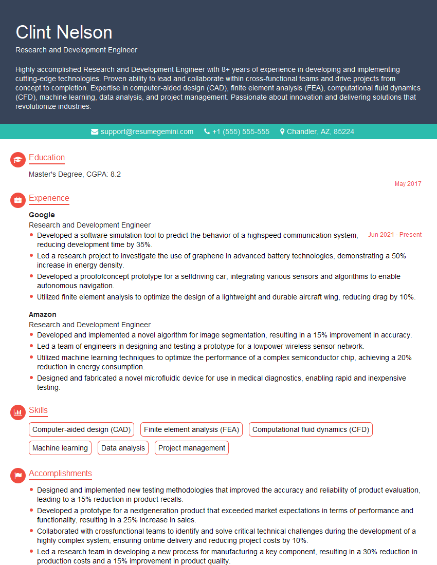
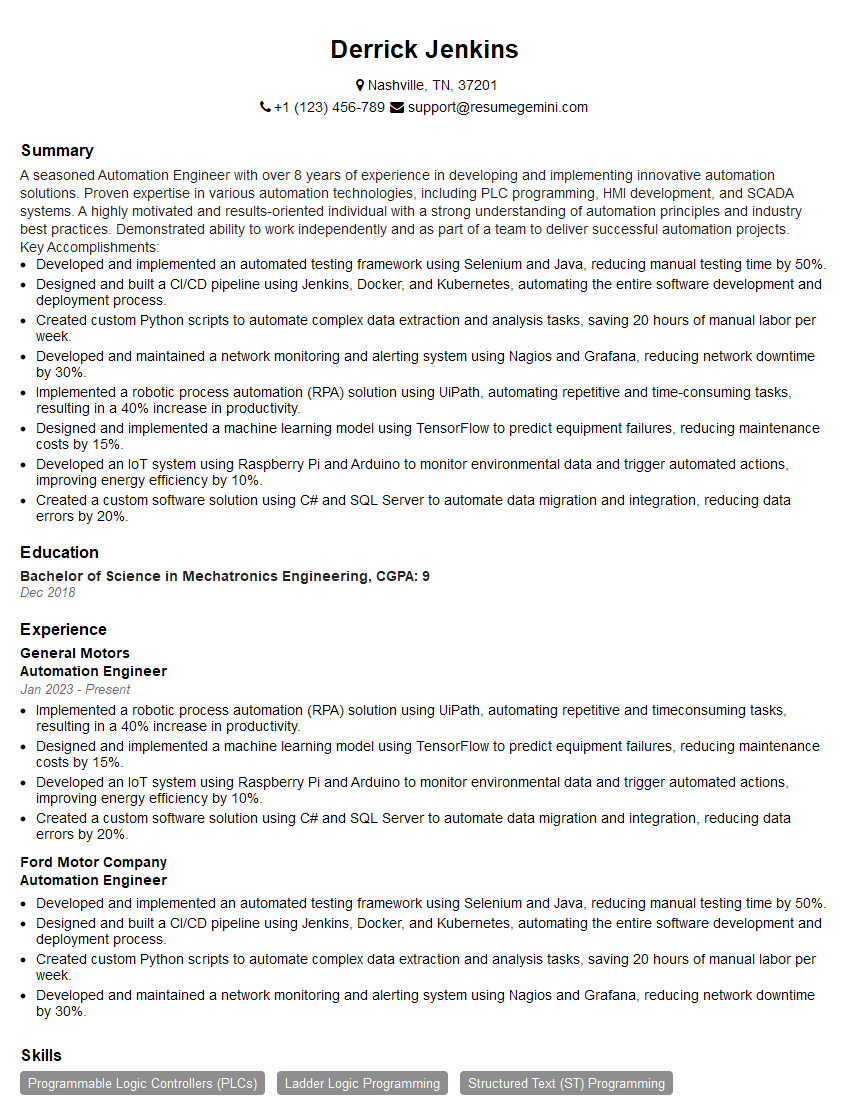
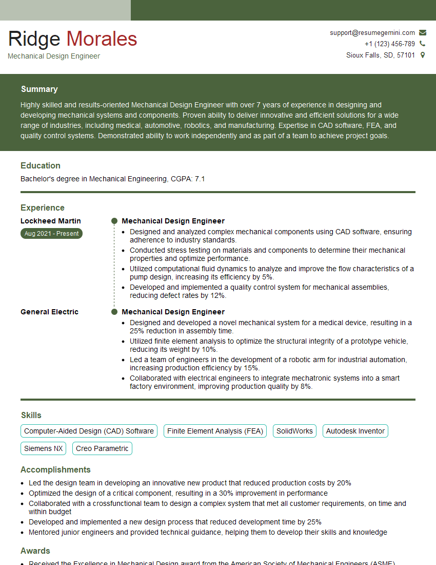
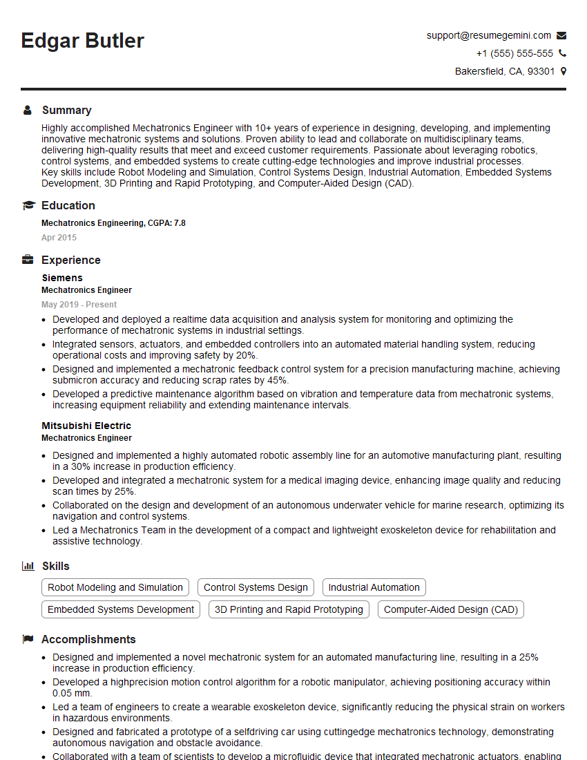
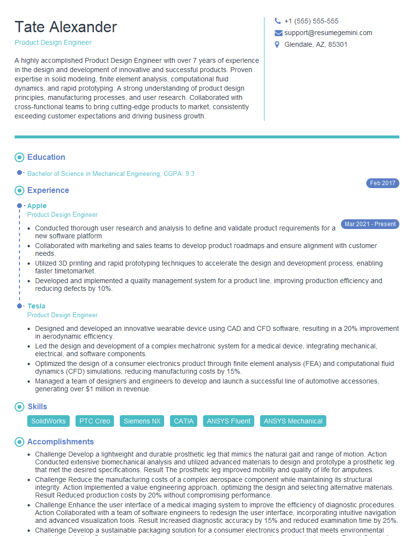
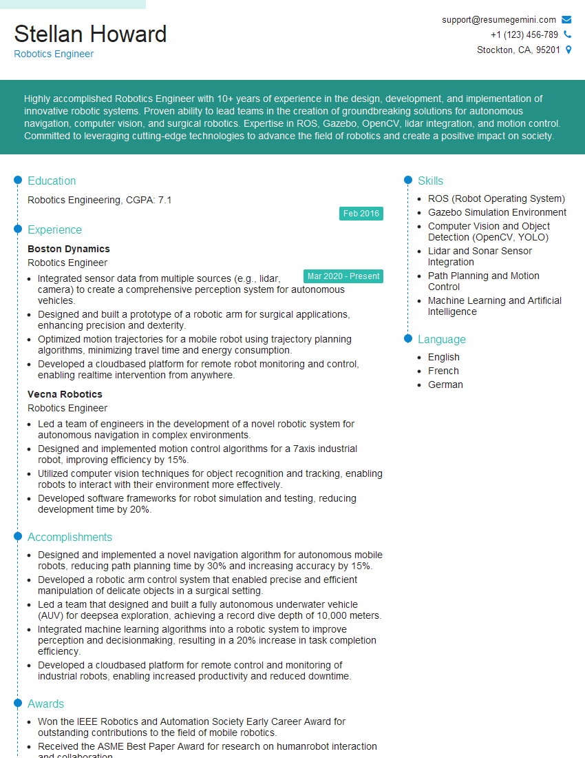
Mastering Mechanical Design and Engineering opens doors to exciting and rewarding careers with ample opportunities for growth and innovation. To maximize your job prospects, it’s crucial to present your skills and experience effectively. Creating an ATS-friendly resume is essential for getting your application noticed by recruiters and hiring managers. ResumeGemini is a trusted resource that can help you build a professional and impactful resume that highlights your accomplishments and makes you stand out from the competition. Examples of resumes tailored to Mechanical Design and Engineering are available to guide you.
Explore more articles
Users Rating of Our Blogs
Share Your Experience
We value your feedback! Please rate our content and share your thoughts (optional).
What Readers Say About Our Blog
Very informative content, great job.
good